Datalogic DS2200 Reference Manual
Datalogic laser scanner reference manual
Hide thumbs
Also See for DS2200:
- Installation manua (28 pages) ,
- Quick reference manual (7 pages) ,
- Programming manual (88 pages)
Table of Contents
Advertisement
Quick Links
Download this manual
See also:
Programming Manual
Advertisement
Table of Contents

Related Manuals for Datalogic DS2200


Summary of Contents for Datalogic DS2200
- Page 1 DS2200 Reference Manual...
- Page 3 DS2200 REFERENCE MANUAL...
- Page 4 DATALOGIC S.p.A. Via Candini 2 40012 - Lippo di Calderara di Reno Bologna - Italy DS2200 Reference Manual Ed.: 4/2006 ALL RIGHTS RESERVED Datalogic reserves the right to make modifications and improvements without prior notification. Datalogic shall not be liable for technical or editorial errors or omissions contained herein, nor for incidental or consequential damages resulting from the use of this manual.
-
Page 5: Table Of Contents
Indicators ... 2 Model Description ... 2 Accessories... 3 INSTALLATION... 4 Package Contents... 4 Mechanical Installation... 5 2.2.1 Mounting DS2200 ... 6 Electrical Connections ... 7 2.3.1 Power Supply... 8 2.3.2 Main Serial Interface - RS485 Half-Duplex ... 8 2.3.3 Auxiliary Interface - RS232 ... - Page 6 MAINTENANCE ... 21 Cleaning... 21 TECHNICAL FEATURES ... 22 GLOSSARY... 24 INDEX ... 28...
-
Page 7: References
REFERENCES CONVENTIONS This manual uses the following conventions: “User” or “Operator” refers to anyone using a DS2100A. “Device” refers to the DS2100A. “You” refers to the System Administrator or Technical Support person using this manual to install, mount, operate, maintain or troubleshoot a DS2100A. REFERENCE DOCUMENTATION The documentation related to the DS2100A management is listed below: •... -
Page 8: Safety Precautions
The laser beam can be switched off through a software command (see WinHost Help On Line or the "Command Strings for DS2200" file in the DS2200 directory). Use of controls or adjustments or performance of procedures other than those specified herein may result in exposure to hazardous visible laser light. - Page 9 The warning label indicating exposure to laser light and the device classification is applied onto the body of the scanner (Figure A, 8): For installation, use and maintenance it is not necessary to open the scanner. The laser diode used in this device is classified as a Class 3B laser product according to EN 60825-1 regulations and as a Class IIIb laser product according to CDRH regulations.
-
Page 10: Power Supply
POWER SUPPLY - This product is intended to be installed by Qualified Personnel only. - DS2200 All Models: This device is intended to be supplied either by a UL Listed NEC Class 2 power source, or a UL listed ITE Limited Power Source (LPS), rated 5Vdc, minimum 0.4A. -
Page 11: General View
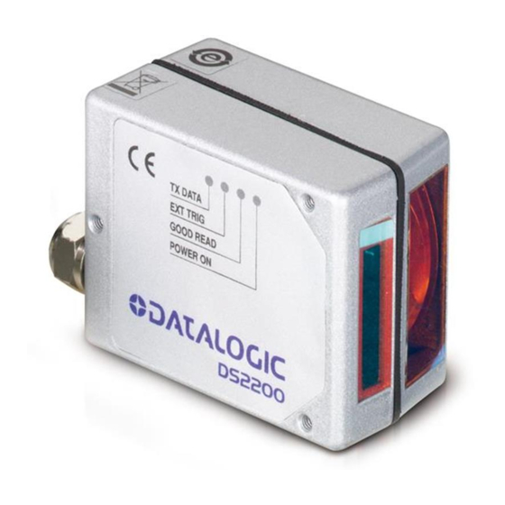
GENERAL VIEW Barcode Image Input Window Laser Beam Output Window Power On LED Good Read LED DS2200 Figure A Ext Trig LED TX Data LED Mounting Holes Laser Warning and Device Class Label... -
Page 12: Guide To Installation
Read all information in the section "Safety Precautions” at the beginning of this manual. Correctly position and mount the scanner for barcode reading according to the information in par. 2.2, 2.4 and 3.4. Provide correct system cabling according to the signals necessary (see all applicable sub-paragraphs under 2.3). -
Page 13: Introduction
INTRODUCTION INTRODUCTION PRODUCT DESCRIPTION The DS2200 scanner is a cost effective barcode reader complete with decoder designed to satisfy demanding requirements associated with high performance scanning. The DS2200 ultra compact dimensions, based on Datalogic's experience in miniaturized laser components, make the scanner's integration into automated equipment extremely easy. -
Page 14: Indicators
(green), when blinking, indicates data transmission. (Figure A, 6). The screw holes on the body of the reader are for mechanical fixture (Figure A, 7). MODEL DESCRIPTION The DS2200 scanner is available in versions that differ in regard to the following parameters: •... -
Page 15: Accessories
INTRODUCTION The following models are therefore available: DS2200 - X X X X Optical Resolution 1 = Standard Resolution 2 = High Resolution Communication Interface 1 = RS232 + RS485 The following tables display each version’s reading performance. Version 1XXX... -
Page 16: Installation
INSTALLATION PACKAGE CONTENTS Verify that the DS2200 reader and all the parts supplied with the equipment are present and intact when opening the packaging; the list of parts includes: • DS2200 reader with cable • Installation Manual • Bar code test chart (PCS = 0.9) •... -
Page 17: Mechanical Installation
INSTALLATION MECHANICAL INSTALLATION DS2200 can be installed to operate in any position. There are three screw holes (M2.5 x 5) on the body of the reader for mounting. The diagram below gives all the information required for installation; refer to par. 2.4 for correct positioning of the scanner with respect to the code passage zone. -
Page 18: Mounting Ds2200
DS2200 2.2.1 Mounting DS2200 Using the DS2200 mounting bracket you can obtain the most suitable position for the reader as shown in the figure below: Pitch Skew... -
Page 19: Electrical Connections
INSTALLATION ELECTRICAL CONNECTIONS The DS2200 cable is equipped with a 25-pin female D-sub connector for connection with the power supply and input/output signals: Do not connect GND and SGND to different (external) ground references. GND and SGND are internally connected through filtering circuitry which can be permanently damaged if subjected to voltage drops over 0.8 Vdc. -
Page 20: Power Supply
2.3.1 Power Supply The following pins of the DS2200 connector are used: DS2200 CHASSIS The power must be 5 Vdc only. 2.3.2 Main Serial Interface - RS485 Half-Duplex The RS485 half-duplex interface (3 wires + shield) is used for polled communication protocols. -
Page 21: Auxiliary Interface - Rs232
DS2200 (up to 31) DS2200 DS2200 MULTIPLEXER Figure 6 - DS2200 Multidrop connection to a Multiplexer 2.3.3 Auxiliary Interface - RS232 The auxiliary serial interface is used exclusively for RS232 point-to-point connections. It is also used for configuring the DS2200. -
Page 22: Inputs
EXT TRIG- I/O REF The EXT TRIG input is used to connect the external trigger which tells the scanner to scan for a code. The active state of this input is selected in software. Refer to the WinHost Help On Line. -
Page 23: Outputs
These outputs are both level or pulse configurable. POSITIONING The DS2200 scanner is able to decode barcode labels at a variety of angles, however significant angular distortion may degrade reading performance. When mounting the DS2200 take into consideration these three ideal label position angles: Pitch 0°, Skew 15°... - Page 24 The Skew angle is represented by the value S in Figure 11. Position the reader to assure about 15° for the Skew angle. This avoids the direct reflection of the laser light emitted by the DS2200. For the raster version, this angle refers to the most inclined or external raster line, so that all other raster lines assure more than 15°...
-
Page 25: Typical Layouts
In this layout data is transmitted to the Host on the RS232 Auxiliary serial interface. The Local Echo communication mode must be enabled (default) see the WinHost Help On Line. When On-Line Operating mode is used, the scanner is activated by an External Trigger (photoelectric sensor) when the object enters its reading zone. DS2200 2.5.2... - Page 26 The Master scanner is also connected to the Host on the RS232 auxiliary serial interface. The External Trigger signal is unique to the system; there is a single reading phase and a single message from the Master scanner to the Host computer.
-
Page 27: Multiplexer
MX4000 The auxiliary serial interface can be used in Local Echo mode to control any single scanner (visualize collected data) or to configure it using the WinHost utility or Host Mode programming procedure. When On-Line Operating mode is used, the scanner is activated by an External Trigger (photoelectric sensor) when the object enters its reading zone. -
Page 28: Reading Features
READING FEATURES The number of scans performed on the code by the DS2200 and therefore the decoding capability is influenced by the following parameters: • number of scans per second • code motion speed • label dimensions • scan direction with respect to code motion At least 5 scans during the code passage should be allowed to ensure a successful read. -
Page 29: Picket-Fence Mode
READING FEATURES For example, the DS2200 (500 scans/sec.) for a 25 mm high code moving at 500 mm/s performs: PICKET-FENCE MODE DS2200 Figure 17 - "Picket Fence" scanning mode If scanning is parallel to the code motion, (Figure 17), the number of effective scans... -
Page 30: Performance
PERFORMANCE The DS2200 scanner is available in different versions according to the reading performance. Version 1XXX 2XXX Version 1XXX 50 mm (2.0 in) - 220 mm (8.7 in) on 0.60 mm (24 mils) codes 2XXX 40 mm (1.6 in) - 125 mm (4.9 in) on 0.20 mm (8 mils) codes Refer to the diagrams given in par. -
Page 31: Reading Diagrams
READING FEATURES READING DIAGRAMS The following diagrams show the reading distance for barcodes with different densities. DS2200-1XXX (Standard Resolution) 0.15 mm (6 mils) (mm) (in) NOTE: (0,0) is the center of the laser beam output window CONDITIONS: Code = Interleaved 2/5 or Code 39 = 0.90... - Page 32 DS2200-2XXX (High Resolution) 0.10 mm (4 mils) (mm) (in) NOTE: (0,0) is the center of the laser beam output window. CONDITIONS: Code = Interleaved 2/5 or Code 39 = 0.90 "Pitch" angle = 0° "Skew" angle = 15° "Tilt" angle = 0°...
-
Page 33: Maintenance
Repeat the operation frequently in particularly dirty environments. Use soft material and alcohol to clean the windows and avoid any abrasive substances. Clean the windows of the DS2200 when the scanner is turned off or, at least, when the laser beam is deactivated. WARNING... -
Page 34: Technical Features
(Note 1) Safety class READING FEATURES Scan rate Aperture angle Max. Reading distance Maximum resolution USER INTERFACE LED indicators DS2200-1XXX 5 Vdc ± 5% RS485 Half-Duplex RS232 150 to 115200 External Trigger User-defined OUT1 and OUT2 50 Vdc 50 mA continuous 0.3V at 10 mA max. - Page 35 TECHNICAL FEATURES SOFTWARE FEATURES READABLE CODE SYMBOLOGIES • EAN/UPC (including Add-on 2 and Add-on 5) • 2/5 Interleaved • Code 39 (Standard and Full ASCII) • Codabar Other symbologies available on request Code Selection Decoding Safety Headers and Terminators Operating Modes Configuration Modes Parameter Storage ENVIRONMENTAL FEATURES...
-
Page 36: Glossary
Datalogic devices are in compliance with the CDRH regulations. Code Positioning Variation in code placement that affects the ability of a scanner to read a code. The terms Pitch, Skew, and Tilt deal with the angular variations of code positioning in the X, Y and Z axes. - Page 37 Rotation of a code pattern about the X-axis. The normal distance between center line or adjacent characters. See pars. 2.2.1 and 2.4. Position The position of a scanner or light source in relation to the target of a receiving element.
- Page 38 Host system. Serial Port An I/O port used to connect a scanner to your computer, identifiable by a 9-pin or 25- pin connector. Signal An impulse or fluctuating electrical quantity (i.e.: a voltage or current) the variations of which represent changes in information.
- Page 39 Trigger Signal A signal, typically provided by a photoelectric sensor or proximity switch, which informs the scanner of the presence of an object within its reading zone. Acronym for Universal Product Code. The standard barcode type for retail food packaging in the United States.
-
Page 40: Index
Interfaces Auxiliary – RS232; 9 Main – RS485 Half Duplex; 8 Laser Safety; vi LED Indicators; 2 Maintenance; 21 Model Description; 2 Mounting DS2200; 6 Outputs; 11 Package Contents; 4 Performance; 18 Picket-Fence Mode; 17 Positioning; 11 Power Supply; viii Raster;... - Page 41 Gerät declare que el DS2200-XXXX Laser Scanner sono conformi alle Direttive del Consiglio Europeo sottoelencate: are in conformity with the requirements of the European Council Directives listed below: sont conformes aux spécifications des Directives de l'Union Européenne ci-dessous: der nachstehend angeführten Direktiven des Europäischen Rats:...