Datalogic DS8100A Reference Manual
Datalogic scanning barcode reader scanner reference manual
Hide thumbs
Also See for DS8100A:
- Reference manual (141 pages) ,
- Reference manual (123 pages) ,
- Reference manual (92 pages)
Table of Contents
Advertisement
Quick Links
Advertisement
Table of Contents

Related Manuals for Datalogic DS8100A


Summary of Contents for Datalogic DS8100A
- Page 1 DS8100A Reference Manual...
- Page 3 DS8100A REFERENCE MANUAL...
- Page 4 Via Candini 2 40012 - Lippo d i Calderara di Reno Bologna - Italy DS8100A Reference Manual Ed.: 07/2006 ALL RIGHTS RESERVED atalogic reserves the right to make modifications or improvements without prior notification. Datalogic shall not be liable for technical or editorial errors or omissions contained herein, nor for ncidental or consequential damages resulting from the use of this material.
-
Page 5: Table Of Contents
INSTALLATION ... 6 Package Contents ...6 Mechanical Mounting...7 2.2.1 Mounting the Scanner... 7 2.2.2 Mounting the Scanner with Accessories... 8 Electrical Connections ...10 2.3.1 Main/Aux. Serial Interface and I/O Connector ... 11 Main Interface ... 12 Auxiliary Interface ... 14 Inputs ... - Page 6 Advanced Code Reconstruction (ACR™ 4)...53 4.1.1 Tilt Angle for Advanced Code Reconstruction ... 53 PackTrack™ ...54 4.2.1 PackTrack™ Calibration for DS8100A ... 56 4.2.2 PackTrack™ Calibration for DS8100A Oscillating Mirror Models ... 58 Performance ...58 4.3.1 Reading Conditions ... 58 Reading Diagrams ...60 MAINTENANCE ...
-
Page 7: References
REFERENCES REFERENCE DOCUMENTATION The documentation related to the DS8100A management is listed below: • C-BOX100 Installation Manual • PWR series power supply unit Installation Manuals • PWO power supply unit Installation Manual • GFC-80 90° deflecting mirror • GFC-800 90° deg. mirror close distance •... -
Page 8: Compliance
The laser light is visible to the human eye and is emitted from the window on the side of the scanner (Figure A). provided to comply with the rules imposed by international orrect use of the DS8100A scanner. make sure the power cable is though staring directly at the laser... -
Page 9: Power Supply
(30 mW at 630~680 nm). POWER SUPPLY This scanner is intended to be supplied by either a UL Listed power supply marked 'Class 2' or 'LPS', output rated 20 – 30 V dc , minimum 1.5 A or by a UL Listed computer with LPS outputs. -
Page 10: General View
GENERAL VIEW Laser Beam Output Window Laser Safety Label Product Label Warning and Device Class Label viii DS8100A Figure A – DS8100A Connector Panel Display Service Access Cap Mounting Holes... - Page 11 DS8100A Figure B – DS8100A Oscillating Mirror Version Laser Beam Output Window Laser Safety Label Figure C – Display and Keypad Panel Programming Keypad Power On LED (Green) Phase On LED (Yellow) Encoder LED (Yellow) TX Data LED (Green) Network LED (Red)
- Page 12 Figure D – Connector Panel for Standard Models Lonworks 17-pin male connector Lonworks 17-pin female connector Figure E – Connector Panel for Ethernet Mo Lonworks 17-pin male connector Lonworks 17-pin female connector Serial interface and I/O 26-pin connector dels Serial interface and I/O 26-pin connector Harting RJ industrial connector...
-
Page 13: Guide To Installation
2.5 and par. 4.4. Make electrical connections to your DS8100A scanner by: a) Connecting the DS8100A scanner to the C-BOX 100 by means of one of the CAB-601X cables provided as accessory (see par. 1.5). -
Page 14: Master/Slave Lonworks Installation
Completing the system wiring adding as many slave scanners as required by your system layout (refer to par. 2.6.5). d) Correctly providing bus return to the last DS8100A Slave reader of the network according to the information given under “Local Lonworks Network” in par. 2.3.2 and par. - Page 15 7) Send the configuration to the Master. 8) Optionally, perform the ASR Network Configuration procedure for system backup purposes (see par. 5.2.1). 9) Exit the configuration program and run your application. The installation is now complete. xiii...
-
Page 17: Introduction
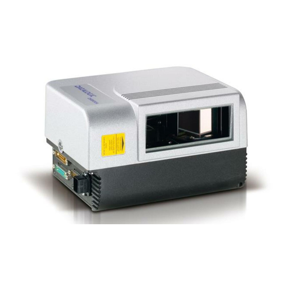
1 INTRODUCTION 1.1 PRODUCT DESCRIPTION The DS8100A scanner is a barcode reader complete with decoder designed to provide an innovative and high performance solution in omnidirectional reading applications by combining the following advanced technologies with Datalogic solid experience in the material handling sector. - Page 18 • The high frequency laser diode modulation system guarantees complete immunity to ambient light and allows installation of the DS8100A in any working area. • As a result of the ASTRA™ multiple laser technology, DS8100A gives a great real time DOF even on high speed conveyors.
-
Page 19: Model Description
Oscillating mirror models are used when coverage of a large reading area is required, mainly in picket fence applications. The oscillating mirror is placed in front of the reading aperture of the DS8100A scanner to deflect the laser beam. As the mirror moves, this sweeping function of the laser beam allows the coverage of a larger area to locate the barcodes. -
Page 20: Indicators
Indicates the Lonworks network is functioning correctly. This LED is normally ON. • These LEDs are always OFF when the DS8100A works as Slave. the raster width to the minimum necessary, the number of s of the software configuration parameters see... -
Page 21: Accessories
1.5 ACCESSORIES The following accessories are available on request for DS8100A: Name Description PWR-120 J-box power unit 110/230 VAC 24 V 120 W PWR-240 J-box power unit 110/230 VAC 24 V 240 W PWR-480 J-box power unit 110/230 VAC 24 V 480 W... -
Page 22: Installation
DS8100A reader to other devices in the system (i.e. C-BOX 100 etc.). NOTE 2.1 PACKAGE CONTENTS Verify that the DS8100A reader and all the parts supplied with the equipment are present and intact when opening the packaging; the list of parts includes: •... -
Page 23: Mechanical Mounting
2.2 MECHANICAL MOUNTING 2.2.1 Mounting the Scanner DS8100A can be installed to operate in any position. There are 16 screw holes (M6 X 8) on the sides of the scanner for mounting. The diagram below can be used for installation; refer to par. -
Page 24: Mounting The Scanner With Accessories
Figure 5 - DS8100A Oscillating Mirror Model Overall Dimensions 2.2.2 Mounting the Scanner with Accessories The following accessories allow installing the DS8100A reader in the most suitable position for your network layout: ST-163 mounting bracket; FBK-8100 fast bracket. The ST-163 is a 90° mounting bracket to be mounted on the reader as displayed in the image below: Figure 6 –... - Page 25 The FBK-8100 is a fast bracket kit allowing quick and easy mounting of the scanner on the ST-163 bracket. It is particularly useful when performing a scanner automatic replacement (see par. 5.2), since the scanner can be simply substituted with a new one while maintaining its physical position within the network.
-
Page 26: Electrical Connections
Standard Ethernet The table below gives the pinout of the C-BOX 100 terminal block connectors. Use this pinout when the DS8100A reader is connected in a network by means of the C-BOX 100: C-BOX 100 Terminal Block Connectors 1, 3, 5... -
Page 27: Main/Aux. Serial Interface And I/O Connector
2.3.1 Main/Aux. Serial Interface and I/O Connector The DS8100A Standard and Fieldbus models are equipped with a 26-pin male D-sub connector for connection to the host computer, power supply and input/output signals. The details of the connector pins are indicated in the following table:... -
Page 28: Main Interface
The RTS and CTS signals control data transmission and synchronize the connected devices. If the RTS/CTS hardware protocol is enabled, the DS8100A activates the RTS output to indicate a message can be transmitted. The receiving unit must activate the CTS input to enable the transmission. - Page 29 RTX485 + RTX485 - GND-ISO Figure 12 – RS485 Half-Duplex Interface Connections Function RS485 output (+) RS485 input (+) RS485 output (-) RS485 input (-) Main signal ground DS8100A USER INTERFACE TX485+ RX485+ RX485+ TX485+ TX485- RX485- RX485- TX485- GND_ISO...
-
Page 30: Auxiliary Interface
DS8100A Figure 13 - RS232 Auxiliary Interface Connections Inputs The inputs of the reader are on the 26-pin connector of the DS8100A. These inputs are called EXT_TRIG/PS, IN2/ENC, IN3 and IN4. Name EXT_TRIG/PS A External trigger (polarity insensitive) for PS... - Page 31 DS8100A + 5V Figure 14 – PNP Command Input Connection using External Power DS8100A + 5V Figure 15 - PNP Command Input Connection using Scanner Power DS8100A + 5V Figure 16 - NPN Command Input Connection using External Power DS8100A...
- Page 32 + 5V Figure 19 - IN3/IN4 NPN Input Command using Scanner Power Input devices can be supplied by either scanner power (VS and GND) or external power supplies (Vext). Electrical isolation between the input command logic and the scanner is maintained when powering the input devices from an external supply voltage (Vext).
-
Page 33: Outputs
40 mA although 130 mA may be reached in pulse conditions. DS8100A Figure 20 – Output 1 and Output 2 Interface When the load is powered by an external power supply, the voltage must be less than 30 V. -
Page 34: Lonworks Input/Output Connector
Collector current (continuous) 150 mA Max. R on R off Off-state leakage current Maximum power dissipation DS8100A The command signal is filtered and generates a delay of about 50 µs for OUT1 and OUT2 and 1 ms for OUT3. 2.3.2 Lonworks Input/Output Connector INPUT (male) Figure 22 - Lonworks INPUT/OUTPUT Connectors The following pinout is valid for the INPUT connector as well as for the OUTPUT connector. -
Page 35: Network Termination
CAB-8605 is a power and Lonworks termination cable to be used for connecting the DS8100A master to an external power unit within the network; while CAB-8305 is a power and bus return cable to be used for connecting the last DS8100A slave to an external power unit. -
Page 36: Lonworks Interface
The Lonworks network is used for both input and output connection to build a multi-sided or omni-station system connecting several readers. The DS8100A master usually employs the 17-pin female connector for output connection to the first slave, while the 17-pin male connector is terminated by inserting the BTK8102 terminator (see Figure 23 for details). - Page 37 The diagram below represents the termination of the double Lonworks line of a DS8100A working as master by means of the BTK-8102. The diagram below represents the Lonworks bus return of a DS8100A working as slave by means of the BTK-8100.
-
Page 38: Ethernet Connector
2.3.3 Ethernet Connector This connector is only available for DS8100A Ethernet models and allows the Ethernet connection between the host and the reader. Figure 29 – Harting RJ Industrial® Push Pull Male Connector Figure 30 – DS8100A Harting RJ Industrial® Female Connector This interface and the connector pinout (see the following table) are IEEE 802.3 10 BaseT... -
Page 39: Ethernet Interface
The supply voltage for correct operation of the scanner must be between 20 and 30 VDC. The max. power consumption is 30 W including startup current. Several accessory power supplies are available to power the DS8100A(s) and reading station components. See par. 1.5. -
Page 40: User Interface
Trigger 2.5 POSITIONING THE SCANNER The DS8100A scanner is able to decode barcode labels at a variety of angles, however significant angular distortion may degrade reading performance. When mounting the DS8100A take into consideration these three ideal label position angles: Pitch 0°, Skew 0°... - Page 41 INSTALLATION The Pitch angle is represented by the value P in Figure 34. Position the reader in order to minimize the Pitch angle. Figure 34 - "Pitch" angle The Skew angle is represented by the value S in Figure 35. Figure 35 - "Skew"...
-
Page 42: Typical Layouts
DS8100A 2.6 TYPICAL LAYOUTS The DS8100A scanners can be connected in a variety of layouts depending on the number of scanners used and the required complexity of the reading station. These layouts range from Single Stand Alone to Complex Lonworks Networks. -
Page 43: Point-To-Point
In this case no External Trigger is used and the C-BOX 100 only supplies the reader. The DS8100A (Ethernet model) is connected to a fieldbus remote Host. It can be activated by a signal generated by the remote Host or always be active if working in Automatic operating mode. -
Page 44: Pass Through
2.6.2 Pass Through When Pass Through is activated on the Auxiliary interface, the DS8100A reader can be integrated in a network consisting of different scanners not provid terface. This co nnection mode allows two or more devices to be connected to a single external serial terface. -
Page 45: Rs232 Master/Slave
Figure 40 – Pass Through Connection for Fieldbus Models 2.6.3 RS232 Master/Slave The RS232 master/slave connection is used to integrate a DS8100A reader in a network consisting of diff erent scanners not provided with a Lonworks interface. The Sla e scan ners use RS232 only on the main and auxiliary interfaces. - Page 46 Slave 1 C-BOX 100 Auxiliary Serial Interface Main Serial Interface P.S. (Presence Sensor) connected to External Trigger/PS input. Figure 41 – RS232 Master/Slave for DS8100A Standard Models Remote PLC * P.S. (Presence Sensor) connected to External Trigger/PS input. Auxiliary Serial Interface Main Serial Interface Figure 42 –...
-
Page 47: Multiplexer
INSTALLATION 2.6.4 Multiplexer The Multiplexer connection is used to integrate a DS8100A slave reader in a Multidrop network consisting of different scanners not provided with a Lonworks interface. Each scanner connected Multiplexer (MX4000) with RS485 half-duplex main interface. P.S.* P.S.* P.S.*... -
Page 48: Local Lonworks Network
2.6.5 Local Lonworks Network A local Lonworks network allows logically connecting a DS8100A master reader with up to 31 DS8100A slaves. Actually, the maximum number of readers to be employed in the network depends on the system operating conditions, that is adopted operating mode and amount of data stream. -
Page 49: Small Synchronized Network
INSTALLATION Small Synchronized Network When building a small local Lonworks network (less than 10 scanners), the DS8100A master reader must be connected to a local host computer or a C-BOX 100 by means of a cable connected to the 26-pin D-sub male connector. - Page 50 Slave 2 Slave 1 CAB810X P.S. (Presence Sensor) connected to External Trigger/PS input. C-BOX 100 modified to accept scanner power. Encoder connected to IN2/ENC input. Figure 45 – Small Synchronized Network with more than 2 Readers and Single Power Unit CAB830X...
-
Page 51: Large Synchronized Network
External devices such as a presence sensor and an encoder are all connected to the PWO. Host ETHERNET SC6000 CAB-810x CAB-810x DX8200A CAB-810x scanners per DS8100A Figure 46 – Large Synchronized Network with DX8200A and DS8100A Scanners CAB-SC6103 Cable Power/Net CAB-SC6003 CAB-SC6003 Extended I/O LONWORKS BTK8100 CAB-810x... - Page 52 DS8100A SC6000 Conveyor Figure 47 – Large Synchro nized Ne twork Reading Station...
-
Page 53: Redundant System
Power/Net CAB-SC6003 CAB-SC6003 Extended I/O LONWO -810x CAB-810x CAB-810X DX8200A Redundancy CAB-PWO Power/Net CAB-SC6003 CAB-SC6003 Extended I/O LONWORKS CAB-810x CAB-810X CAB-810x DX8200A VAC INPUT ENCODER PS Aux BTK8100 CAB-810x DS8100A DS8100A VAC INPUT ENCODER PS Aux BTK8100 CAB-810x DS8100A DS8100A... -
Page 54: Multidata Network
Multidata Network s layout, one master and up to 7 DS8100A slave the fore multiple read ing p turn connected to its relative scanne he master sends all the individual messages collected from the Lonworks interface as well s its own to the Local Host through its C-BOX 100. -
Page 55: Fieldbus Network
2.6.6 Fieldbus Network The Fieldbus (Ethernet) model offers connectivity without any converter or adapter needed. The DS8100A master Fieldbus communicates with a remote host (for ex. remote PC connected via Internet) by means of a cable connected to the Fieldbus (Ethernet) connector provided. -
Page 56: Keypad And Display
KEYPAD AND DISPLAY The DS8100A keypad allows entering a menu for selection of one of the following functions: • Welcome: shows the current sof • Autolearn: starts the procedure making it possible to obtain an automatic, accurate and fast configuration of DS8100A without the necessity of directly checking/modifying the relevant parameters;... -
Page 57: Software Configuration
Figure 51 - Genius™ Wizard Opening Window The Wizard option is advised to low skilled users, since it shows a step by step scanner configuration. The parameters to be defined are the following: Barcode selection and definition;... -
Page 58: Test Operating Mode
Sending the configuration to the scanner. Figure 52 - Genius™ Wizard Closing Window est Operating Mode This operating mode is not available when DS8100A works as slave. NOTE This operating mode causes the reader to be continuously activated allowing to verify its reading features and its reading position with respect to the barcode. -
Page 59: On Line Operating Mode
EXT TRIG/PS A and EXT TRIG/PS B inpu During the active phase of the presence sensor, the DS8100A reader tries to acquire and correctly decode the code. case the decoding phase is successful, the barcode characters are transmitted on the serial interface. -
Page 60: Genius™ Network Setup Through Master
6.40 or later. NOTE . The first operation to perform is the configuration of your scanner as "Master" from the Local Device Network Settings item in the Device Menu, see figure below: Figure 56 – Local Device Network Settings... - Page 61 “Devices” area appear next to the Parameter Explorer window. By repeatedly clicking the icon this area will be displayed or hidden. Each scanner of the cluster is indicated by the following graphical objects: • check box allowing to select/deselect a specific scanner to perform the desired operations (i.e.
-
Page 62: Net-Autoset
Network Wizard procedure Express Network Setup procedure Net-Autoset This procedure is to be used when all scanner addresses and labels are unknown (typically when configuring the network for the first time or whenever a network reconfiguration is required). By clicking the icon or selecting the "Net_Autoset"... -
Page 63: Network Wizard
The added slave scanner will be then displayed in the “Requested Devices” area. This option in any case requires that all slave scanners have their address set before the network can function. - Page 64 2. If desired, select a slave scanner within the "Current Devices" area and click on the icon (or select the "Show Device" option from the right-click menu) to make the dialog box appear as follows: The "Show Device" option is particularly useful after the Net-Autoset procedure or whenever it is necessary to know which address is assigned to a specific slave scanner.
-
Page 65: Alternative Slave Address Assignment
By choosing this option it is possible either to start a new scanner configuration or to open and modify an old one. The desired parameters can be defined in the following window, similar to the MS Explorer: Figure 58 - Genius™... -
Page 66: Parameter Default Values
.4 PAR AMETER DEFAULT VALUES The following table contains the list of the factory default settings for the DS8100A. Genius™ also allows checking the paramete parameters" option available in the Tools menu and comparing the current scanner configuration to the default one. - Page 67 Parameter Reading Parameters Overflow Stop Ratio Reading Mode Reading Condition Reconstruction Parameters Enabled Stacked Code Extended Min Match Position Tolerance Duration Tolerance Min Start/Stop Number Inter Char Gap Addon Overflow Ration Scan Line Amplitude Amplitude Settings Enable PackTrack Calibration Direction PS Offset Data Communication Settings Host Application Protocol Type...
- Page 68 Parameter Auxiliary Serial Port Data Tx Hea tbeat Pass Through Parameters Baud Rate Parity Data Bits Stop Bits Digital I/O Setting Digital Input Lines Setting Debouncing For Input 1, 3 and 4 Debouncing For Input 2 Input 1 Active Level Overridden by Op. Mode Active Closed Input 2 Active Level Overridden by Op.
-
Page 69: Reading Features
With just a set of partial scans on the label (obtained using the motion of the label itself), the DS8100A is able to “reconstruct” the barcode. A typical set of partial scans is shown in the figure below: Code Direction None of the partial scans contains the whole label. -
Page 70: Packtrack
™ ackTrack™ is a patented operating mode for Datalogic Omni-Directional Reading Stations used to read and correctly assign codes read on different packs when placed in the scanner Reading Area at the same time. In fact, in the following example, the codes of two or more consecutive packs are found at the same time in the scanner reading area. - Page 71 For correct functioning, the PackTrack™ operating mode requires a calibration just after the installation of the scanners. This opera tion is absolutely necessary to make the scanner cognize its position in space. Thus, a fixed reference system is required. PackTrack™ uses a right-handed reference system (right hand with thumb = X axis;...
-
Page 72: Packtrack™ Calibration For Ds8100A
Select the “SPY” option from the Tools menu or click on the related icon on the Genius™ toolbar to open the following dialog box: Note: When selecting a slave scanner through the Master, click on the slave to calibrate in the Devices window, then click the SPY icon. - Page 73 By selecting the “PackTrack Calibration” option a further dialog box appears allowing to st alibra Position 1 Position 2 Position 3 Figure 67 – Performing the PackTrack™ Calibration 1. Place the code at the desired position on the scan line (i.e. Position 1) 2.
-
Page 74: Packtrack™ Calibration For Ds8100A Oscillating Mirror Models
4.2.2 PackTrack™ Calibration for DS8100A Oscillating Mirror Models The DS8100A oscillating mirro when the scanner is mounted s tha he shown in the following fi gure: Conveyor Direct Figure 68 – Oscillating Mir PackTrack™ Calibration must be made while the conveyor plane and fixed (not oscillating). - Page 75 Conveyor Speed (m/s) 0.25 0.30 Code 39 0.33 Code Resolution 0.38 (mm) 0.50 0.72 1.00 Ratio 3:1; Interdigit = Module Size Conveyor Speed (m/s) 0.25 0.30 Code 128 – Ean 128 0.33 Code Resolution 0.38 (mm) 0.50 0.72 1.00 Conveyor Speed (m/s) 0.25 0.30 Codabar...
-
Page 76: Reading Diagrams
4.4 READING DIAGRAMS DS8100A-2X10 (0.50 mm/20 mils) The diagram shows an average reading area obtained considering different barcode types of ariable quality. -700 (in) (cm) te : (0,0) is the center of the laser beam output window. CONDITIONS Code = Interl eaved 2/5 or Code 39 = 0.9... - Page 77 DS8100A-2X10 (0.38 mm/15 mils) The diagram shows an average reading area obtained considering different barcode types of variable quality. -700 (cm) (in) Note : (0,0) is the center of the laser beam output window. CONDITIONS Code = Interleaved 2/5 or Code 39 = 0.90...
- Page 78 DS8100A-3X00 (0.50 mm/20 mils) The diagram shows an average reading area obtained considering different barcode types of variable quality. -700 (cm) (in) : (0,0) is the center of the laser beam output window. CONDITIONS Code = Interle aved 2/5 or Code 39 = 0.9...
- Page 79 DS8100A-3X10 (0.38 mm/15 mils) The diagram shows an average reading area obtained considering different barcode types of variable quality. (cm) (in) te : (0,0) is the center of the lase CONDITIONS Code = Inter leaved 2/5 or Code 39 = 0.9 "Pitch"...
- Page 80 DS8100A-3X20 (0.30 mm/12 mils) The diagram shows an average reading area obtained considering different barcode types of variable quality. (in) (cm) te : (0,0) is the center of the laser beam output window. CONDI TIONS Code = Interle aved 2/5 or Code 39 = 0.9...
- Page 81 DS8100A-3X30 (0.25 mm/10 mils) The diagram shows an average reading area obtained considering different barcode types of variable quality. (cm) (in) Note : (0,0) is the center of the laser beam output window. CONDITIONS Code = Interleaved 2/5 or Code 39 = 0.90...
- Page 82 DS8100A-3X05 (0.50 mm/20 mils) The diagram shows an average reading area obtained considering different barcode types of variable quality. -700 (cm) (in) Note : (0,0) is the center of the laser beam output window. CONDITIONS Code = Interleaved 2/5 or Code 39 = 0.90...
- Page 83 DS8100A-3X15 (0.38 mm/15 mils) The diagram shows an average reading area obtained considering different barcode types of variable quality. (cm) (in) te : (0,0) is the center of the lase CONDITIONS Code = Interl eaved 2/5 or Code 39 = 0.9 "Pitch"...
- Page 84 DS8100A-3X25 (0.30 mm/12 mils) The diagram shows an average reading area obtained considering different barcode types of variable quality. (cm) (in) te : (0,0) is the center of the laser beam output window. CONDI TIONS Code = Interle aved 2/5 or Code 39 = 0.9...
- Page 85 DS8100A-3X35 (0.25 mm/10 mils) he diagram shows an average reading area obtained considering different barcode types of variable quality. (in) (cm) Note : (0,0) is the center of the laser beam output window. CONDITIONS Code = Interleaved 2/5 or Code 39 = 0.90...
-
Page 86: Maintenance
Dust, dirt, etc. on the window may alter the reading performance. eat the operation frequently in particularly dirty environments. soft material and alcohol to clean the window and Clean the window of the DS8100A when the scanner least when the laser be ARNING .2 AUTOMATIC SCANNER REPLACEMENT (ASR) -
Page 87: Scanner Replacement Procedure
5.2.2 Scanner Replacement Procedure The ASR procedure requires replacing one scanner at a time. NOTE lave 1. Power down the entire 2. Rep lace the Slave scanner with a n 3. Powe r up the system and wait for in a Master 1. -
Page 88: Troubleshooting
6 TROUBLESHOOTING Before contacting your loc it is suggested to save the the Genius™ softw model and serial number. NOTE Problem Power On: the “Power On” LED is not lit. On Line Mode: the Master’s “Phase On” LED is not lit (when external trigger activates). - Page 89 Problem On Line Mode and Serial On Line Mode: the reader does not respond correctly to the expected external signal end. Reading: it is not possible to read the target barcode (always returns No Read) Communication: the device is not transmitting anything to the host.
- Page 90 How do I obtain my units’ serial numbers? TROUBLESHOOTING GUIDE Suggestion • If the LED is OFF, check the connections between the DS8100A slaves and the SC6000 or DS8100 A master. If contact your Datalogic distributor. • The device serial number is printed on that is affixed above the connector p the reader.
-
Page 91: Technical Features
TECHNICAL FEA ELECTRICAL FEATURES Supply voltage Power consumption Common Communication Interfaces Model–Dependent Communication Ethernet Interfaces Inputs Ext. Trigger 1, 3 aux. digital inputs Outputs 3 software program mable digital Outputs OPTICAL FEATURES Light receiver Wavelength Safety class Light source Laser control READING FEATURES Scan rate Maximum resolution... - Page 92 SOFTWARE FEATURES Readable Codes Code selection Headers and Terminators Operating modes Configuration modes Parameter storage ENVIRONMENTAL FEATURES Operating temperature Storage temperature Humidity Ambient light immunity Vibration resistance IEC 68-2-6 test FC 2 hours on each axis Shock resistance: IEC 68-2-27 test EA 3 shocks on each axis Protection class PHYSICAL FEATURES...
-
Page 93: Glossary
Code Positioning Variation in code placement that affects the ability of a scanner to read a code. The t Pitch, Ske w, and Tilt deal with the angular variations of code positioning in the X, Y and Z axes. - Page 94 Rotation of a code pattern about the X-axis. The normal distance between center line or adjacent characters. See par. 2.5. osition he position of a scanner or light source in relation to the target of a receiving element. rotocol A formal set of conventions governing the formatting and relative timing of message exchange between two communicating systems.
- Page 95 Host system. rial Port An I/O port used to connect a scanner to your com Signal impulse or fluctuating electrical quantity (i.e.: a voltage or current) the variations of which represent cha nges in information.
-
Page 96: Index
Parameter Explorer Window; 49 ositioning; 24 Power Supply; 23 Reading Diagrams; 60 Reading Features; 53 Reference Documentation; v Scanner Assignment using Keypad; 40 Scanner Rep lacement; 70 Service nd Support; v Software Config uration; 41 Technical Features; 75 Terminators; 19 Test Mode using Keypad;... - Page 97 Gerät declare que el DS8100A-XXXX, Laser Scanner sono conformi alle Direttive del Consiglio Europeo sottoelencate: are in conformity with the requirements of the European Council Directives listed below: sont conformes aux spécifications des Directives de l'Union Européenne ci-dessous: den nachstehenden angeführten Direktiven des Europäischen Rats:...