Datalogic DS4800 Reference Manual
Datalogic scanner reference manual
Hide thumbs
Also See for DS4800:
- Reference manual (105 pages) ,
- Quick reference manual (16 pages) ,
- Quick reference manual (13 pages)
Table of Contents
Advertisement
Advertisement
Table of Contents

Related Manuals for Datalogic DS4800


Summary of Contents for Datalogic DS4800
- Page 1 DS4800 Reference Manual...
- Page 2 Datalogic Automation Srl Via S. Vitalino, 13 40012 - Lippo di Calderara di Reno Bologna - Italy DS4800 Reference Manual Ed.: 09/2008 ALL RIGHTS RESERVED Datalogic reserves the right to make modifications and improvements without prior notification. Datalogic shall not be liable for technical or editorial errors or omissions contained herein, nor for incidental or consequential damages resulting from the use of this material.
-
Page 3: Table Of Contents
2.4.1 Display Messages... 26 Accessories ... 29 INSTALLATION ... 30 Package Contents ... 30 Mechanical Installation ... 31 3.2.1 Mounting DS4800 ... 33 Positioning ... 35 CBX ELECTRICAL CONNECTIONS... 37 Power Supply... 38 Main Serial Interface... 38 4.2.1 RS232 Interface... 39 4.2.2 RS485 Full-Duplex Interface... - Page 4 Auxiliary RS232 Interface ... 48 Inputs ... 49 4.5.1 Code Verifier... 52 Outputs ... 52 User Interface - Host... 54 25-PIN CABLE ELECTRICAL CONNECTIONS ... 55 Power Supply... 56 Main Serial Interface... 56 5.2.1 RS232 Interface... 57 5.2.2 RS485 Full-Duplex Interface... 58 5.2.3 RS485 Half-Duplex Interface ...
-
Page 5: References
“You” refers to the System Administrator or Technical Support person using this manual to install, mount, operate, maintain or troubleshoot a DS4800. REFERENCE DOCUMENTATION The documentation related to the DS4800 management is listed below: CBX100 Installation Manual • CBX500 Installation Manual •... -
Page 6: Safety And Compliance Notices
LASER SAFETY The following information is provided to comply with the rules imposed by international authorities and refers to the correct use of the DS4800 scanner. Standard Regulations This scanner utilizes a low-power laser diode. Although staring directly at the laser beam momentarily causes no known biological damage, avoid staring at the beam as one would with any very strong light source, such as the sun. -
Page 7: Fcc Compliance
This product is intended to be installed by Qualified Personnel only. This accessory device is intended to be supplied by a UL Listed or CSA Certified Power Unit with «Class 2» or LPS power source, which supplies power directly to the scanner via the 25- pin connector. -
Page 8: Handling
HANDLING The DS4800 is designed to be used in an industrial environment and is built to withstand vibration and shock when correctly installed, however it is also a precision product and therefore before and during installation it must be handled correctly to avoid damage. - Page 9 • do not weld the scanner into position which can cause electrostatic, heat or output window damage. • do not spray paint near the scanner which can cause output window damage.
-
Page 10: General View
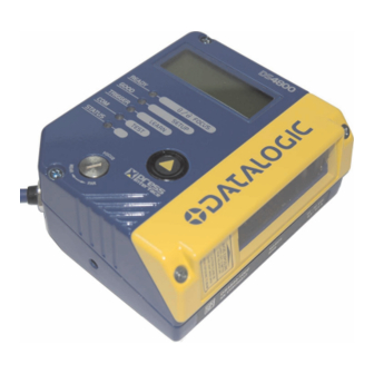
GENERAL VIEW "POWER ON" LED Focus Adjustment Indicator LEDs DS4800 Figure A Display Laser Beam Output Window Push Button... -
Page 11: Rapid Configuration
This chapter illustrates a Stand Alone application. For other types of installations, such as ID-NET™, Fieldbus, Pass-Through, Multiplexer Layout, etc., refer to chapters 4, 5 and 6. For complete scanner configuration using the Genius™ configuration program, refer to the Context-Sensitive Help On-Line. - Page 12 CBX100/500 Pinout for DS4800 The table below gives the pinout of the CBX100/500 terminal block connectors. Use this pinout when the DS4800 reader is connected by means of the CBX100/500: CBX100/500 Terminal Block Connectors Input Power Power Supply Input Voltage +...
- Page 13 25-pin Connector Pinout for DS4800 The table below gives the pinout of the 25-pin male D-sub connector for connection to the power supply and input/output signals. Use this pinout when the DS4800 reader is connected by means of the 25-pin connector:...
-
Page 14: Step 2 - Mount And Position The Scanner
STEP 2 – MOUNT AND POSITION THE SCANNER 1. To mount the DS4800, use the mounting bracket to obtain the most suitable position for the reader as shown in the figures below. Figure 3 - Positioning with Mounting Bracket 2. When mounting the DS4800 take into consideration these three ideal label position angles: Skew 15°... -
Page 15: Step 3 - Focus The Scanner
This screw moves the internal lens of the scanner to change the focal length of the scanner. The setting is continuous but should not be set beyond the limits "Too Far" or "Too Near" which appear on the display at the extremes of the focus range. -
Page 16: Step 4 - X-Press™ Configuration
Fieldbus network. During the reader startup (reset or restart phase), all the LEDs blink for one second. On the back of the reader near the cable, the “POWER ON” LED indicates the laser scanner is correctly powered. - Page 17 Auto Learn If you are configuring your scanner using X-PRESS™, you must start with the Auto Learn procedure. 1. Enter the Auto Learn function by holding the X-PRESS™ push button pressed until the LEARN LED is on. 2. Release the button to enter the Auto Learn function.
- Page 18 SETUP LED is on. 2. Release the button to enter the Auto Setup function. 3. Once entered, if a barcode label is positioned in front of the scanline, the scanner automatically performs the optimal setup of the reading parameters for that specific barcode.
- Page 19 NOTE Reset Scanner to Factory Default (Optional) If it ever becomes necessary to reset the scanner to the factory default values, you can perform this procedure by holding the X-PRESS™ push button pressed while powering up the scanner. At the end of the procedure (about 5-6 seconds), the Configuration and nvironmental parameters are reset, a "D...
-
Page 20: Step 5 - Install Genius™ Configuration Program
This configuration procedure assumes scanner connection to a CBX100/500. Genius™, running on a laptop computer, is connected to the scanner auxiliary port through the CBX100/500 9-pin connector. To communicate with the scanner, Genius™ performs an auto baudrate detection starting from its default parameters which are 115200, 8, N, 1. - Page 21 RAPID CONFIGURATION 1. Select the Create a new configuration button. You will be guided through the configuration being asked to define the following parameters: Barcode selection and definition...
- Page 22 Operating mode selection and definition Digital Outputs configuration...
- Page 23 Hardware interface selection Output data format configuration The On Line operating Mode requires the reader to be connected to an External Trigger/Presence Sensor using I1A and I1B inputs. The Automatic operating mode does not require connection to an external Presence Sensor.
- Page 24 2. After defining the parameter values the following window appears allowing to complete the reader configuration as follows: Saving the configuration to disk; • Switching to Advanced mode; • Sending the configuration to the scanner. • 3. After sending the configuration to the scanner you have completed the configuration process. 4. By...
-
Page 25: Step 6 - Test Mode
TEST LED is on. 2. Release the button to enter the Test mode function. Once entered, the Bar-Graph on the five LEDs is activated and if the scanner starts reading barcodes the Bar-Graph shows the Good Read Rate. In case of no read condition, only the STATUS LED is on and blinks. -
Page 26: Advanced Scanner Configuration
By choosing this option it is possible either to start a new scanner configuration or to open and modify an old one. The desired parameters can be defined in the following window, similar to the MS Explorer:... - Page 27 ID-NET™ is in addition to the Main and Auxiliary serial interfaces. If you need to install an ID-NET™ network refer to the DS4800 Reference Manual. The scanner can also be configured by reading programming barcodes. See the ID- NET™...
-
Page 28: Introduction
2 INTRODUCTION 2.1 PRODUCT DESCRIPTION The DS4800 laser scanner satisfies the most advanced needs of a wide range of users. It has been developed focusing on the realistic requirements of its target market. The outstanding result is an extremely compact, cost-effective and easy to use industrial scanner. -
Page 29: Indicators
Fieldbus network. During the reader startup (reset or restart phase), all the LEDs blink for one second. On the back of the reader near the cable, the “POWER ON” LED indicates the laser scanner is correctly powered. - Page 30 All scanners are typically located far away from each other and they use a dedicated presence sensor. At the end of each reading phase, each scanner transmits its own data message to the host. Thanks to ID-NET™, data collection among readers is accomplished at a high speed without the need of an external multiplexing device.
-
Page 31: How To Setup/Configure The Scanner Network
(500 kbs is the default value). It can be changed after network setup using Genius™ through the Master scanner. See also the alternative procedure in the note below. 3. At the prompt to "Send updated Network configuration to the Local Device" (Master) choose "Yes". -
Page 32: X-Press™ Human Machine Interface
At the same time one or more LEDs lig t up a READY FOCUS GOOD SETUP TRIGGER LEARN TEST STATUS DS4800 also shows specific diagnostic messages on its display, see par. 2.4 for details. ccor ding to the foll owing scheme: STATUS READY BLINK ON to indicate any Failure differ GOOD Motor or Laser failures. -
Page 33: X-Press™ Functions
AutoSetup Test Mode Function Once entered, the Bar-Graph on the five LEDs is activated and if the scanner starts reading barcodes the Bar-Graph shows the Good Read Rate. In case of no read condition, only the STATUS LED is on and blinks. - Page 34 Multi Label mode is enabled (refer to the “2K/4K Family Software Configuration Parameter Guide” Help file). exit the process by pressing the X-PRESS™ push button once. The scanner will restart at the end of the process, and then the detected barcodes are automatically configured in scanner memory. AutoSetup Function Once entered, if a barcode label is positioned in front of the scanline, the scanner automatically performs the optimal setup of the reading parameters for that specific barcode.
-
Page 35: Display
"Default Set" is shown on the display. 2.4 DISPLAY The DS4800 is equipped with a 2 line by 16 character LCD display which shows various diagnostic, menu and operating mode messages according to a defined priority (0 = top priority):... -
Page 36: Display Messages
• Italian • Japanese 2.4.1 Display Messages The following examples of DS4800 Local Display messages are given to help interpret the information reported. Test Mode Results: A = reading percentage from 000 to 100%. Z = code content. F = focus distance in given in centimetres and inches. - Page 37 Slave Node Alarms: X = slave node number (1-31) Y = numeric error value Reading Results: A = reading result – Good (Good Read), Part (Partial Read), Mult (Multiple Read) X = code content Y = number of codes read X = code content Y = number of digits in the code DGT = "digits"...
- Page 38 The display alternates between message 1 and 2. Message 1 Message 2 S = Slave diagnostic condition: * = scanner OK - =scanner not detected at startup ? =scanner detected at startup but not responding to diagnostic polling ! = scanner diagnostic error...
-
Page 39: Accessories
2.5 ACCESSORIES The following accessories are available on request for the DS4800: Name Description BK-4000 L-Shape Bracket BK-4001 U-Shape Bracket CBX100 Compact Connection Box CBX100LT Compact Connection Box Low Temp CBX500 Modular Connection Box BM100 Backup Module BM150 CBX500 Display Module... -
Page 40: Installation
3 INSTALLATION 3.1 PACKAGE CONTENTS Verify that the DS4800 reader and all the parts supplied with the equipment are present and intact when opening the packaging; the list of parts includes: DS4800 reader with cable • DS4800 Quick Guide •... -
Page 41: Mechanical Installation
INSTALLATION 3.2 MECHANICAL INSTALLATION DS4800 can be installed to operate in different positions. The four screw holes (M4 x 5) on the body of the reader are for mechanical fixture to the L-shaped mounting bracket. There are also three screw holes (M5 x 3) for fixture to the U-shaped mounting bracket (Accessory). - Page 42 Ø4.2 [Ø0.17] N°4 Figure 14 – L Shape Mounting Bracket Overall Dimensions [1.18] [2.91] [in] Figure 15 – (Accessory) U Shape Mounting Bracket Overall Dimensions Ø4.2 [Ø0.17] N°4 [0.17] [0.17] 30° Ø8.1 [Ø0.32] N°2 [0.32] N°8 [2.76] [3.15] [4.25] [0.12] 76.9 [3.03] Ø5.5...
-
Page 43: Mounting Ds4800
INSTALLATION 3.2.1 Mounting DS4800 Using the DS4800 mounting bracket you can quickly and easily obtain standard mounting positions (i.e. 15° Skew angles) for the reader as shown in the following figures: Skew Pitch -45° -15° 0° 15° 45° Figure 16 – Positioning with L Shape Mounting Bracket... - Page 44 DS4800 REFERENCE MANUAL Skew -45° -15° alignment marks 0° 15° 45° Pitch Figure 17 – Positioning with U Shape Mounting Bracket (Accessory)
-
Page 45: Positioning
INSTALLATION 3.3 POSITIONING The DS4800 scanner is able to decode moving barcode labels at a variety of angles, however significant angular distortion may degrade reading performance. When mounting the DS4800 take into consideration these three ideal label position angles: Skew 15° to 30°, Tilt 0° and Pitch 0°. - Page 46 DS4800 REFERENCE MANUAL The Pitch angle is represented by the value P in Figur e 20. Position the reader in order to inimize the Pitch angle. Figure 20 - Pitch Angle...
-
Page 47: Cbx Electrical Connections
Chaper 5. NOTE The table below gives the pinout of the CBX100/500 terminal block connectors. Use this pinout when the DS4800 reader is connected by means of the CBX100/500: Power Supply Input Voltage + Power Supply Input Voltage -... -
Page 48: Power Supply
To avoid electromagnetic interference when the scanner is connected to a CBX connection box, verify the jumper positions in the CBX as indicated in its Installation Manual. NOTE 4.1 POWER SUPPLY Power can be supplied to the scann as shown in Figure 21: Power Supply The power must be between 10 and 30 Vdc only. -
Page 49: Rs232 Interface
S signals control data transmission and synchronize the con TRANSMISSION TX DATA IDLE If the RTS/CTS handshaking protocol is enabled, the DS4800 activates the RTS output to indicate a message is to be transmitted. The receiving unit activates the CTS input to enable the transmission. Function... -
Page 50: Rs485 Full-Duplex Interface
Function RS485 Transmit Data + RS485 Receive Data + RS485 Transmit Data - RS485 Receive Data - Signal Ground USER INTERFACE RX485+ TX485+ SGND RX485- SCANNER SGND TX+ R INTERFACE RX485+ SGND RX485- SCANNER SGND TX+ TX485- lines... -
Page 51: Rs485 Half-Duplex Interface
In a Multiplexer layout, the Multidrop address must also be set via serial channel by the Genius™ utility or by the Host Programming Mode. Figure 27 shows a multidrop configuration with DS4800 scanners connected to a Multiplexer. This is an example of multidrop wiring. Consult the multiplexer manual for complete wiring instructions. - Page 52 DS4800 REFERENCE MANUAL Figure 27 - DS4800 Multidrop Connection to a Multiplexer...
-
Page 53: Id-Net™ Interface
Wire dimensioning must be checked in order to avoid voltage drops greater than 0.8 Volts. Cable should lie down as near as possible to the ID-NET™ cable (avoiding wide loops between them). Scanner's chassis may be • Network inside the same building. •... -
Page 54: Id-Net™ Response Time
4.3.2 ID-NET™ Response Time The following fi gure shows the response time of the ID-NET™ network. This as the period between the Trigger activation nd the beginning of data transmission to the Host. CONDITIONS: • ID-NET™ M/S Synchronized layout • message length = 50 bytes per node Max ID-NET™... - Page 55 CBX ELECTRICAL CONNECTIONS Figure 29 – ID-NET™ Network Connections with isolated power blocks...
- Page 56 DS4800 REFERENCE MANUAL Figure 30 - ID-NET™ Network Connections with Common Power Branch Network...
- Page 57 CBX ELECTRICAL CONNECTIONS Figure 31 – ID-NET™ Network Connections with Common Power Star Network...
-
Page 58: Id-Net™ Network Termination
4.3.3 ID-NET™ Network Termination The network must be properly terminated in the first and last scanner of the network. This is done by setting the ID-NET™ Termination Resis 4.4 AUX ILIARY RS232 INTERFACE he auxiliar y serial interface is u The parameters relative to the aux interface (baud rate, data bits, etc.) as well as particular... -
Page 59: Inputs
This input is optocoupled and can be driven by both an NPN and PNP type command. The connections are indicated in the following diagrams: EXTERNAL TRIGGER INPUT CONNECTIONS USING DS4800 POWER Figure 34 – PH-1 Photocell (PNP) External Trigger Using DS4800 Power 30 Vdc 12 mA (scanner) + 12 mA (CBX... - Page 60 Figure 35 - NPN External Trigger Using DS4800 Power EXTERNAL TRIGGER INPUT CONNECTIONS USING EXTERNAL POWER Figure 36 - PNP External Trigger Using External Power Figure 37 - NPN External Trigger Using External Power NPN Photocell Power to Input Photocell...
- Page 61 Function Power Source - Inputs Input 2 A (polarity insensitive) Input 2 B (polarity insensitive) Power Reference - Inputs INPUT 2 CONNECTIONS USING DS4800 POWER PNP Input 2 Using DS4800 Power NPN Input 2 U PUT 2 CONN ECTIONS U...
-
Page 62: Code Verifier
Figure 39 - NPN Input 2 Using External Power .5.1 Code Verifier If the DS4800 is used as a Code Verifier, the verifier code can be configured in software through the Genius™ configuration program. However it is also possible to use one of the inputs to trigger when the scanner should store a code read as the verifier code. - Page 63 Figure 40 - Open Emitter O Output Device Power to Output device Figure 41 - Open Collector Output Using DS4800 Power OUTPUT CONNECTIONS USING EXTERNAL POWER Pulled up to External Output Device Power Figure 42 - Open Emitter Output Using External Power...
-
Page 64: User Interface - Host
4.7 USER INTERFACE - HOST he following table contains the pinout for standard RS232 PC Host interface. For other user interface types please refer to their own manual. 9-pin male connector RS232 PC-side connections 25-pin male connector Name Name... -
Page 65: 25-Pin Cable Electrical Connections
5 25-PIN CABLE ELECTRICAL CONNECTIONS ll DS4800 models are equipped with a cable term r connection to the power supply and input/output signals. The details of the connector pins are indicated in the following table. 25-pin D-sub male con Name... -
Page 66: Power Supply
5.1 POWER SUPPLY Power can be supplied to the scanner through the pins provided on the 25-pin connector used for communication with the host (Figure 45): DS4800 The power must be between 10 and 30 Vdc only. is recommended to connect pin 1 (CHASSIS) to a common earth ground. -
Page 67: Rs232 Interface
S signals control data transmission and synchronize the con TRANSMISSION TX DATA IDLE If the RTS/CTS handshaking protocol is enabled, the DS4800 activates the RTS output to indicate a message is to be transmitted. The receiving unit activates the CTS input to enable the transmission. Function... -
Page 68: Rs485 Full-Duplex Interface
RS232 communications or in electrically noisy environments. he connector pinout follows: 25-pin Name DS4800 Chassis Figure 48 - RS485 Full-duplex Connections For applications that do not use RX signals, do not leave these lines but connect them to GND as shown below. -
Page 69: Rs485 Half-Duplex Interface
In a Multiplexer layout, the Multidrop address must also be set via serial channel by the Genius™ utility or by the Host Programming Mode. Figure 51 shows a multidrop configuration with DS4800 scanners connected to a Multiplexer. This is an example of multidrop wiring. Consult the multiplexer manual for complete wiring instructions. - Page 70 DS4800 REFERENCE MANUAL Figure 51 - DS4800 Multidrop Connection to a Multiplexer...
-
Page 71: Id-Net™ Interface
Wire dimensioning must be checked in order to avoid voltage drops greater than 0.8 Volts. Cable should lie down as near as possible to the ID-NET™ cable (avoiding wide loops between them). Scanner's chassis may be connected to earth. • Network inside the same b •... -
Page 72: Id-Net™ Response Time
5.3.2 ID-NET™ Response Time The following figure shows the response time of the ID-NET™ network. This time is defined as the period between the Trigger activation and the beginning of data transmission to the Host. CONDITIONS: • ID-NET™ M/S Synchronized layout •... - Page 73 25-PIN CABLE ELECTRICAL CONNECTIONS Figure 53 – ID-NET™ Network Connections with isolated power blocks...
- Page 74 DS4800 REFERENCE MANUAL Figure 54 - ID-NET™ Network Connections with Common Power Branch Network...
- Page 75 25-PIN CABLE ELECTRICAL CONNECTIONS Figure 55 – ID-NET™ Network Connections with Common Power Star Network...
-
Page 76: Id-Net™ Network Termination
5.3.3 ID-NET™ Network Termination The network must be properly terminated by a 120 Ohm resistor at the first and last scanner of the network. .4 AUXIL IARY RS232 INTERFACE The auxiliary serial interface is used exclusively for RS232 point-to-point connections. -
Page 77: Inputs
This input is optocoupled and can be driven by both an NPN and PNP type command. The connections are indicated in the following diagrams: EXTERNAL TRIGGER INPUT PNP PH-1 DS4800 Figure 57 - PH-1 Photocell (PNP) External Trigger Using DS4800 Power 30 Vdc 12 mA Function... - Page 78 EXTER NAL T RIGGER IN DS4800 Figure 58 - PNP External Trigger Using DS4800 Power DS4800 Figure 59 - NPN External Trigger using DS4800 power EXTERNAL TRIGGER INPUT CONNECTIONS USING EXTERNAL POWER DS4800 Figure 60 - PNP External Trigger Using External Power...
- Page 79 25-pin Name INPUT 2 CONNECTIONS USING DS4800 POWER DS4800 Figure 62 - PNP Input 2 Using DS4800 Power DS4800 Figure 63 - NPN Input 2 Using DS4800 Power INPUT 2 CONNECTIONS USING EXTERNAL POWER DS4800 Figure 64 - PNP Input 2 Using External Power...
-
Page 80: Code Verifier
5.5.1 Code Verifier If the DS4800 is used as a Code Verifier, the verifier code can be configured in software through the Genius™ configuration program. However it is also possible to use one of the inputs to trigger when the scanner should store a code read as the verifier code. -
Page 81: User Interface - Host
PC RS232 COM port connections. 25-pin D-sub male DS4800 Trigger USER INTERFACE 8/11 22/12 RS232 PC-side connections 25-pin male connector Name Vdc (10 – 30 Vdc) Power GND Test Cable for DS4800 Vext 30 Vdc max. Name 9-pin D-sub female Power Supply... -
Page 82: Typical Layouts
In Local Echo communication mode, data is transmitted on the RS232 auxiliary interface independently from the main interface selection. When On-Line Operating mode is used, the scanner is activated by an External Trigger (photoelectric sensor) when the object enters its reading zone. - Page 83 Local Echo communication mode, data is transmitted on the RS232 auxiliary interface independently from the Fieldbus interface selection. hen On-Line Operating mode is used, the scanner is activated by an External Trigger (photoelectric sensor) when the object enters its reading zone.
-
Page 84: Pass-Through
Pass-through mode allows two or more devices to be connected to a single external serial interface. Each DS4800 transmits the messages received by the Auxiliary interface onto the Main interface. All messages will be passed through this chain to the host. - Page 85 (Master and Slaves) to accept input on the Auxiliary interface, for example to connect a device such as a hand-held reader for manual code reading capability. ach DS4800 transmits its own messages plus any messages received by its Auxiliary interface onto the ID-NET™ interface. The Master passes all messages to the Host.
-
Page 86: Id-Net
For a Master/Slave Synchronized layout the External Trigger signal is unique to the system; there is a single reading phase and a single message from the master scanner to the Host computer. It is not necessary to bring the External Trigger signal to all the scanners. - Page 87 For a Master/Slave Multidata layout each scanner has its own reading phase independent from the others; each single message is sent from the master scanner to the Host computer. Master Power Host The auxiliary serial interface of the slave scanners can be used in Local Echo communication mode to control any single scanner (visualize collected data) or to configure it using the Genius™...
- Page 88 This requires using an acce the CBX500 connection box. System confi guration can be accomplished through the Auxiliary interface of the Mast scanner (internal CBX500 9-pin connector) using the Genius™ configuration program or enius™ based Host Mode programming. Power Master Host Figure 74 –...
-
Page 89: Rs232 Master/Slave
Master. The Master scanner is connected to the Host on the RS232/RS485 main serial interface. There is a single reading phase and a single message from the master scanner to the Host computer. -
Page 90: Multiplexer Layout
MX4000 The auxiliary serial interface of the slave scanners can be used in Local Echo communication mode to control any single scanner (visualize collected data) or to configure it using the enius™ utility or Genius™ based Host Mode programming procedure. -
Page 91: Reading Features
With just a set of partial scans on the label (obtained using the motion of the label itself), the scanner is able to “reconstruct” the barcode. A typical set of artial scans is shown in the figure below: Code Direction None of the partial scans contains the whole label. -
Page 92: Tilt Angle For Advanced Code Reconstruction
+ α max α max as shown in the and - No Read While tilt angles of 45° can be obtained, DS4800 scanners are not designed to create o mni- X-pattern. NOTE eter in Advanced Code Reconstruction is the value of the Laser Beam α... -
Page 93: Advanced Code Reconstruction Reading Conditions
7.1.2 Advanced Code Reco • ANSI Grade B minimu • 800 scans/sec • three codes enabled simul neo sly • uniform background The foll owing t ables de scribe he minimum c de h ight requirements (i ACR4™ applications de pendin on he code symbology. - Page 94 0.38 (mm) 0.50 0.72 1.00 To maximi ze scanner performance in Advan ed Reading applications, used in the application and disable any code symbologies that will not be NOTE used in the application. Minimum Code Height for ACR4 Reading (mm) 45°...
-
Page 95: Linear Code Reading
SN = [(LH/LS) * SS] – 2 DS4800 For example, the DS4800 (800 scans/sec.) for a 25 mm high code moving at 1250 mm/s performs: [(25/1250) * 800] - 2 = 14 effective scans. -
Page 96: Picket-Fence Mode
For example, for a 60 mm wide code moving in a point where the reading field is 160 mm wide at a 2000 mm/s speed, the DS4800 (800 scans per sec.), performs: [((160-60)/2000) * 800] - 2 = 38 effective scans... -
Page 97: Performance
7.3 PERFORMANCE The reading performance of the DS4800 scanner depends in part on the focus position setting. Focus F = 30 Near F = 40 Medium F = 60 Far Focus F = 30 Near 21 cm (8.3 in) - 47 cm (18.5 in) on 0.50 mm (20 mils) codes F = 40 Medium 27 cm (10.6 in) - 68 cm (26.8 in) on 0.50 mm (20 mils) codes... -
Page 98: Reading Diagrams
• Parameter selectable in Genius™ For Tilt angles of 45°, the reading p Minimum reading distance: +20 aximum reading distance: -30% aximum reading width: -15% DS4800-1000 Focus Distance 30 cm (Near) ≥ 0.50 mm (20 mils) 0.20 mm 0.30 mm 0.38 mm... - Page 99 Tilt angles of 45°, the reading performance is reduced by approximately the following values: Minimum reading distance: +20% Maximum reading distance: -25% Maximum reading width: -15% DS4800-1000 cus Distance 40 cm (Medium ≥ 0.50 mm (20 mils) 0.30 mm 0.38 mm...
- Page 100 For Tilt angles of 45°, the reading performance is reduced by approximately the following values: Minimum reading distance: +20% Maximum reading distance: -15% Maximum reading width: -15% DS4800-1000 Focus Distance 60 cm (Far) 0.38 mm (15 mils) = Code 128 = 0.90...
-
Page 101: Maintenance
Use soft material and alcohol to clean the window and avoid any abrasive substances. Clean the window of the DS4800 when the scanner is turned off or, at least, when the laser beam is deactivated. -
Page 102: Troubleshooting
9 TROUBLESHOOTING 9.1 GENERAL GUID ELINES hen wiring the devic , pay careful attention to the signal n CBX100/500 spring clamp connectors (chp. 4). If you are connecting directly to the scan 25-pin connector pay atte ntion to the pin number of the signals (chp 5). If you need information about a ce program help files. - Page 103 A message indicating this state is shown on the DS4800 Display. X-PRESS™: X-PRESS™ functions nctions don't work if the scanner motor or laser are turned off. don't work. LEDs light Check if the motor or laser are turned off through the following up but do not allow parameters: access to the functions.
- Page 104 • TROUBLESHOOTING GUIDE • Is the reading distance diagrams)? • Is the scanner correctly fo • Is the Tilt angle too large • Is the Skew angle less than 15° (direct r • Choose the Code Definition branch and enable different Code Symbologies (except Pharmacode).
-
Page 105: Technical Features
10 TECHNICAL FEATURES ELECTRICAL FEA TURES Input Power Supply Voltage Maximum Consumption Serial Interfaces Main Serial Interface Baudrate Auxiliary Baudrate ID-NET™ Baudrate Inputs Input 1 (External Trigger), Input 2 Voltage Current Consumption Minimum Pulse Duration Outputs Output 1, Output 2 Collector Current CE saturation Power Dissipation... - Page 106 SOFTWARE FEATURES READABLE CODES *EAN/UPC (including Add-on 2 and Add-on 5) *2/5 Interleaved *Code 39 (Standard and Full ASCII) *Codabar ABC Codabar Code Selection Decoding Safety Headers and Terminators Operating Modes Configuration Methods Special Functions Parameter Storage USER INTERFACE LED Indicators Multi-function Key Display *Code 93...
-
Page 107: Glossary
CDRH regulations. Code Positioning Variation in code placement that affects the ability of a scanner to read a itch, Skew, and Tilt deal with the angular variations of code positioning in the X, Y and Z axes. - Page 108 Rotation of a code pattern about the X-axis. The normal distance between center line or adjacent characters. See pars. 3.2.1 and Position The position of a scanner or light source in relation to the target of a receiving element. rotocol A form al set of conventions governing the formatting and relative timing of message exchange between two communicating systems.
- Page 109 (barcode) and either passes the uninterpreted data to a decoder or d ecodes the data and passes it on Serial Port An I/O port used to connect a scanner to your connector. Signal An impulse or fluctuating electrical quantity (i.e.: a represent changes in information.
-
Page 110: Index
S232 Interface; 48; 66 CBX Electrical Connections; 3 E Compliance; vii Cleaning; 91 Code Verifier; 52; 70 Display; 25 Display Messages; 26 DS4800 Description; 18 FCC Compliance; vii General View; x Glossary; 97 Handling; viii ID-NET™; 76 ID-NET™ Cables; 43; 61 ID-NET™... -
Page 111: Declaration Of Conformity
Gerät declare que el DS4800-XXXX Laser Scanner; sono conformi alle Direttive del Consiglio Europeo sottoelencate: are in conformity with the requirements of the European Council Directives listed below: sont conformes aux spécifications des Directives de l'Union Européenne ci-dessous: der nachstehend angeführten Direktiven des Europäischen Rats:... - Page 112 www.automation.datalogic.com...