TRENDnet TPE-224WS User Manual
Hide thumbs
Also See for TPE-224WS:
- User manual (106 pages) ,
- Quick installation manual (23 pages) ,
- Troubleshooting (5 pages)
Table of Contents
Advertisement
Advertisement
Table of Contents

Related Manuals for TRENDnet TPE-224WS


Summary of Contents for TRENDnet TPE-224WS
-
Page 2: Fcc Warning
FCC Warning This equipment has been tested and found to comply with the regulations for a Class A digital device, pursuant to Part 15 of the FCC Rules. These limits are designed to provide reasonable protection against harmful interference when the equipment is operated in a commercial environment. - Page 3 UL Warning a) Elevated Operating Ambient Temperature- If installed in a closed or multi-unit rack assembly, the operating ambient temperature of the rack environment may be greater than room ambient. Therefore, consideration should be given to installing the equipment in an environment compatible with the manufacturer's maximum rated ambient temperature (Tmra).
-
Page 4: Table Of Contents
TABLE OF CONT About This Guide ................. 1 Purpose .................... 1 Terms/Usage ..................1 Introduction ..................2 Gigabit Ethernet Technology ............2 Fast Ethernet Technology ..............3 Switching Technology ..............4 VLAN (Virtual Local Area Network) ..........5 ... - Page 5 Discovery List ................19 Monitor List ................... 20 Device Setting ................22 Toolbar ................... 23 Configuring the Switch ..............25 Login ....................25 Setup Setting .................. 27 PoE Port Setting ................. 27 ...
- Page 6 Factory Reset ................64 Backup Setting ................64 Firmware Upload ............... 65 System Reboot ................65 Logout ..................66 Technical Specifications ..............67...
-
Page 7: About This Guide
GBIC Slots. This device integrates 1000Mbps Gigabit Ethernet, 100Mbps Fast Ethernet and 10Mbps Ethernet network capabilities in a highly flexible package. Purpose This guide discusses how to install your TPE-224WS 24-Port 10/100Mbps Web Smart PoE Switch w/ 4 Gigabit Ports and 2 Mini- GBIC Slots. Terms/Usage In this guide, the term “Switch”... -
Page 8: Introduction
INTRODUCTION This chapter describes the features of the TPE-224WS 24-Port 10/100Mbps Web Smart PoE Switch w/ 4 Gigabit Ports and 2 Mini- GBIC Slots and some background information about Ethernet/Fast Ethernet/Gigabit Ethernet switching technology. Gigabit Ethernet Technology Gigabit Ethernet is an extension of IEEE 802.3 Ethernet utilizing the... -
Page 9: Fast Ethernet Technology
In addition, the phenomenal bandwidth delivered by Gigabit Ethernet is the most cost-effective method to take advantage of today and tomorrow’s rapidly improving switching and routing internetworking technologies. And with expected advances in the coming years in silicon technology and digital signal processing that will enable Gigabit Ethernet to eventually operate over unshielded twisted-pair (UTP) cabling, outfitting your network with a powerful 1000-Mbps- capable backbone/server connection creates a flexible foundation for... -
Page 10: Switching Technology
Switching Technology Another approach to pushing beyond the limits of Ethernet technology is the development of switching technology. A switch bridges Ethernet packets at the MAC address level of the Ethernet protocol transmitting among connected Ethernet or Fast Ethernet LAN segments. -
Page 11: Vlan (Virtual Local Area Network)
VLAN (Virtual Local Area Network) A VLAN is a group of end-stations that are not constrained by their physical location and can communicate as if a common broadcast domain, a LAN. The primary utility of using VLAN is to reduce latency and need for routers, using faster switching instead. -
Page 12: Features
Features 24 x 100BASE-TX Auto-MDIX & Auto-negotiation Fast Ethernet PoE ports ( Port 1 ~24) 4 x 1000BASE-T Auto-MDIX & Auto-negotiation Gigabit Ethernet ports (Port 25-28) 2 x 1000BASE-T SX/LX Auto-Sensing Mini GBIC Ports. (Shared with Port 25-26) Supports PoE power up to 15.4W for each PoE port Supports PoE power up to 170W for the device Supports PoE Powered Device (PD) classification identify Half duplex transfer mode for connection speed 10Mbps and... - Page 13 Supports Port Mirroring Supports Port Setting for Speed, Duplex mode and Flow control Web Browser Configuration Windows-Based Utility Standard 19” Rack-mount size...
-
Page 14: Package Contents And Installation
Unpacking Open the box for the Switch and carefully unpacks its contents. The packaging should contain the following items: One TPE-224WS 24-Port 10/100Mbps Web Smart PoE Switch w/ 4 Gigabit Ports and 2 Mini-GBIC Slots Quick Installation Guide Power Cord Utility and User’s Guide CD-ROM... -
Page 15: Rack Mounting
Install the Switch on a sturdy, level surface that can support its weight, or in an EIA standard-size equipment rack. For information on rack installation, see the next section, Rack Mounting. When installing the Switch on a level surface, attach the rubber feet to the bottom of each device. -
Page 16: Connecting Network Cable
Then, use screws provided with the equipment rack to mount each Switch in the rack. Figure 3. Mount the Switch to the rack Connecting Network Cable The Switch has 24 10/100Mbps Power over Ethernet ports. These ports runs both in half and full duplex mode using Cat. 5 cables. These Power over Ethernet will be automatically activated when a compatible terminal is identified. -
Page 17: Ac Power
All Ethernet ports support Auto-MDIX. Users can use either standard or crossover Ethernet cables. There are 2 mini-GBIC slot for optional mini-GBIC module. AC Power The Switch uses 100-240V AC, 50-60 Hz. The Switch’s power supply will adjust to the local power source automatically and may be turned on without having any or all LAN segment cables connected. -
Page 18: Identifying External Components
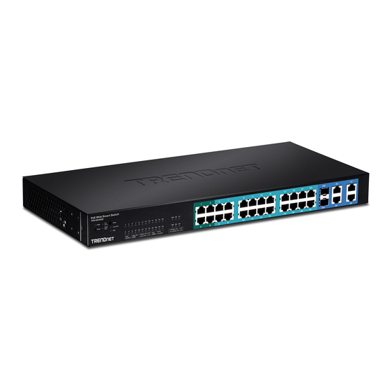
IDENTIFYING EXTERNAL COMPONENTS This chapter describes the front panel and rear panel of the Switch. Front Panel The figure below shows the front panels of the Switch. Figure 4. Front panel LED Indicators: Comprehensive LEDs display the status of the switch and the network (see UNDERSTANDING LED INDICATORS chapter below). - Page 19 These ports support network speeds of either 10Mbps or 100Mbps, and can operate in half- and full- duplex transfer modes. These ports also support auto-MDIX. Users can use either standard or crossover Ethernet cables. 1000BASE-T Gigabit Ethernet Ports (Port 25~28): The Switch’s four Gigabit twisted pair ports support auto negotiation and auto MDIX.
-
Page 20: Rear Panel
Rear Panel The rear panel of the Switch consists of an AC power. The following shows the rear panel of the Switch. Figure 5. Rear panel AC Power Connector: Plug in the female connector of the provided power cord into this connector. -
Page 21: Power And System Leds
Power and System LEDs PWR: Power Indicator : When the Power LED is lit, the Switch is receiving power. When the Power LED is off, the power cord is not connected or is improperly connected. SYS: Management Indicator Blinking : When the CPU is working, the System LED is blinking. On/Off : The CPU is not working. -
Page 22: 1000Base-T/Mini-Gbic Port 25~26 Status Leds
PoE Status Green : When the PoE Status light is green, the PoE powered device (PD) is connected and the port supplies power normally. : When the PoE Status light is red, the PoE port has failed due to one of the following scenarios: PoE power circuit shortage. -
Page 23: 1000Base-T Port 27~28 Status Leds
1000BASE-T Port 27~28 Status LEDs Link/ACT: Link/Activity When the Link/ACT LED is lit, the port is successfully connected to an Ethernet network. Blinking When the Link/ACT LED is blinking, the port is transmitting or receiving data on the Ethernet network. No link. -
Page 24: Configuration
1. Insert the Utility CD in the CD-ROM Drive. 2. Click Install Utility icon to start 3. Follow the on-screen instructions to install the utility. 4. Upon completion, go to Program Files TRENDnet Smart Switch Management Utility and open the Web Smart Management utility. -
Page 25: Discovery List
The Web Management Utility is divided into four sections, Discovery List, Monitor List, Device Setting and Toolbar function. For details instruction, follow the below section. Discovery List This list shows all the Web management devices in the network. Click “Discover” button to list all the Web Management devices in the discovery list. -
Page 26: Monitor List
System word definitions in the Discovery List: IP Address: Shows the current IP address of the device. MAC Address: Shows the MAC Address of the Switch. Protocol version: Shows the protocol version of the Utility. Product Name: Shows the product name of the Switch. System Name: Shows the system name of the Switch. - Page 27 View Trap: The Trap function can receive events that occur from the Web Management Switch listed in the Monitor List. For information on Trap settings using the Web Management Utility refer to the Trap Setting section in the manual. There is a light indicator near the “View Trap” button. A Green light indicates that there has not been any new trap information transmitted.
-
Page 28: Device Setting
Add Item: To add a device to the Monitor List manually, enter the IP Address of the device that you want to monitor. Delete Item: To delete the device in the Monitor List. Device Setting Configuration Setting: Under Configuration Setting, you can set the IP Address, Subnet Mask, Gateway, Set Trap to (Trap IP Address), System name, Location and DHCP function. -
Page 29: Toolbar
Figure 10. Password Change Firmware Upgrade: When the device has a new function, there will be a new firmware to update the device, use this function to update. Select the path of where the firmware updated firmware is located by clicking “Browse”. - Page 30 There are four options under “File”; Monitor Save, Monitor Save As, Monitor Load and Exit. Monitor Save: To record the setting of the Monitor List to the default. The next time you open the utility, it will auto load the default recorded setting. Monitor Save As: To record the setting of the Monitor List with a specific filename and file path.
-
Page 31: Configuring The Switch
Configuring the Switch The TPE-224WS 28-Port 10/100/1000Mbps Gigabit Ethernet Web Smart PoE Switch has a Web GUI interface for smart switch configuration. The Switch can be configured through the Web Browser. A network administrator can manage, control and monitor the switch from the local LAN. This section indicates how to... - Page 32 You can also access the browser configuration through the utility program. Select the device shown in the Monitor List and then click “Web Configuration”. When the login screen appears, enter the default password "admin" and click Login. After entering the password, the page below appears; this screen displays the device status.
-
Page 33: Setup Setting
Setup Setting The following seven links appear under Configuration Setting: Port Setting, IEEE 802.1Q VLAN Settings, Trunk Setting, Mirror Setting, IEEE 802.1p Default Priority, PoE Port Setting, PoE System Setting and Broadcast Strom Control Setting in Setup menu. PoE Port Setting When you click on PoE Port Setting, the PoE Status will appear on the screen. -
Page 34: Port Settings
PoE Enable: Enables or disables the PoE function for the selected port. Power Limit: This function allows you to manually setting the port power current limitation assigned to the Powered Device. To protect the Switch and the connected device, the power limit function will disable the PoE function of the port when the power overloads. - Page 35 Figure 13. Port Setting Note: The priority of Gigabit Fiber port is higher than Copper. Speed: The 1~24 100BASE-TX port connections can operate in Forced Mode settings (100M Full, 100M Half, 10M Full, 10M Half), Auto, or Disable. The default setting for all ports are Auto. The 25~28 1000BASE-T port connections can operate in Forced Mode settings (1000M Full, 100M Full, 100M Half, 10M Full, 10M Half), Auto, or Disable.
-
Page 36: Ieee 802.1Q Vlan
IEEE 802.1Q VLAN A VLAN is a group of ports that can be anywhere in the network, but communicate as though they were in the same area. VLANs can be easily organized to reflect department groups (such as R&D, Marketing), usage groups (such as e-mail), or multicast groups (multimedia applications such as video conferencing), and therefore help to simplify network management by allowing users to move devices to a new VLAN without having to change any physical... - Page 37 Figure 15. Change setting warning message Note: The Settings of VLAN, IGMP Snooping and Forwarding Table will be reset to default. Untag Asymmetric VLAN Setting: The IEEE 802.1Q VLAN Configuration page provides powerful VID management functions. The original default VLAN setting has the VID as 01, named “default”, and contains all ports as “Untagged”.
- Page 38 Add VID: Click to create a new VID group, assigning ports 1 ~ 28 as Untag, Tag, or Not Member. A port can be “Untagged” in only one VID. To save the VID group, press Apply. Figure 17. Add New VID VID: A unique VLAN ID.
- Page 39 Figure 18. Delete VID To change exist IEEE 802.1Q VLAN setting, press the VID to modify that IEEE 802.1Q VLAN setting. Figure 19. Modify VID...
- Page 40 PVID settings: While receiving an untagged frame from the port, the switch will assign a tag to the frame, using the PVID of the port as its VID. Figure 20. PVID Setting Example 1: Here is an example of two VLAN groups with several ports in each group and VLAN 1 (VID 01) does not have communication with VLAN 2 (VID 02).
- Page 41 Figure 22.
- Page 42 Step2: Create VID 02 and set port 1~14 to “Not Member” ports and 15~28 to “Untag” ports member then apply setting. Figure 23. Example2: 802.1Q Asymmetric VLAN settings example: Port 1~28 in VLAN 1, port1~5 in VLAN 2, port1,6~9 in VLAN 3.
- Page 43 Step1: Enable Asymmetric VLAN function. Step2: Set VLAN1 port 1~28 to “Untag” ports, then apply setting.
- Page 44 Step3: Create VID 02 and set port 1~5 to “Untag” ports and port 6~28 to “Not Member” ports, then apply setting. Step 4: Create VID 03 and set port 1, 6~9 to “Untag” ports then apply settings.
-
Page 45: Tag Vlan Setting
Step 5: Set PVID port 2~9 value as below list Note: 1. Untag port VLAN member can exist in different VLAN groups simultaneously when Asymmetric VLAN function enabled. 2. You must create VLAN and add VLAN member first that just can set PVID setting. 3. - Page 46 Example 3: Create two VLAN groups for Tag ports multi-need server application setting and two VLAN clients cannot negotiate to each other. (Asymmetric VLAN function disabled) Step1: Set VLAN1 port 1 to “Tag” port, port 2~14 to “Untag” ports, and port 15~28 to “Not Member”...
- Page 47 Step 2: Set VLAN2 port 1 to “Tag” port, port 15~28 to “Untag” ports, and port 2~14 to “Not Member” ports then apply setting. Note: The multi-need server must be support IEEE 802.1Q VLAN, the sever uplink port is port 1. Example 4: Setting Tag VLAN on two switches.
- Page 48 Step1: Set Switch1’s VLAN1 port 1 to “Tag” and 5~28 to “Not Member”, then apply setting. Step2: Set Switch2’s VLAN1 member as Switch1. Step3: Uplink two switches via Port 1.
-
Page 49: Trunk Setting
Trunk Setting The Trunking function enables the cascading of two or more ports for a combined larger bandwidth. Up to six Trunk groups may be created, each supporting up to 8 ports. Add a Trunking Name and select the ports to be trunked together, and click Apply to activate the selected Trunking groups. -
Page 50: Mirror Setting
Mirror Setting Port Mirroring is a method of monitoring network traffic that forwards a copy of each incoming and/or outgoing packet from one port of the Switch to another port where the packet can be studied. This enables network managers to better monitor network performances. Figure 25. -
Page 51: Ieee 802.1P Default Priority
IEEE 802.1p Default Priority This feature displays the status Quality of Service priority levels of each port, and for packets that are untagged, the switch will assign the priority in the tag depending on your configuration. IEEE 802.1p Default Priority Setting... -
Page 52: Broadcast Storm Control Setting
Broadcast Storm Control Setting The Broadcast Storm Control feature provides the ability to control the receive rate of broadcasted packets. If Enabled (default is Disabled), threshold settings of 8,000 ~ 4,096,000 bytes per second can be assigned. Press Apply for the settings to take effect. Figure 26. -
Page 53: Advanced Setting
Advanced Setting Find that there are four items, including SNMP Setting, Spanning Tree Setting, 802.3x Setting and IGMP Snooping Setting in Advanced menu. SNMP Setting The Web Smart Switch supports SNMP include software (referred to as an agent), which runs locally on the device. A defined set of variables (managed objects) is maintained by the SNMP agent and used to manage the device. - Page 54 SNMP Setting: Enable or Disable the SNMP function on the Web Smart Switch. Community Setting: In support of SNMP version 1, the Web-Smart Switch accomplishes user authentication by using Community Settings that function as passwords. The remote user SNMP application and the Switch SNMP must use the same community string.
-
Page 55: Spanning Tree Setting
Spanning Tree Setting The Web Smart Switch supports IEEE 802.1D Spanning Tree Protocol (STP) implementation is designed to prevent network loops that could cause a broadcast storm. When the physical links forming a loop provide redundancy, only a single path will be forwarding frames. If the link fails, STP activates a redundant link automatically. - Page 56 802.11D Spanning Tree: Enable or Disable the 802.11D Spanning function on the Web Smart Switch. Bridge Priority: This value between 0 and 65535 specifies the priority for forwarding packets: the lower the value, the higher the priority. The default is 32768. Bridge Max Age: This value may be set to ensure that old information does not endlessly circulate through redundant paths in the network, preventing the effective propagation of the new...
-
Page 57: 802.1X Setting
802.1x Setting The IEEE 802.1x provides a security standard for network access control. 802.1x holds a network port disconnected until authentication is completed. Depending on the results, the port is either made available to the user, or the user is denied access to the network. 802.1X uses the Extensible Authentication Protocol (EAP) for passing authentication messages. - Page 58 Authentication Port: Sets primary port for security monitoring. Default is 1812. Key/Confirm Key: Masked password matching the Radius Server Key. TxPeriod: Sets the number of seconds that the switch waits for a response to an EAP-request/identity frame from the client before retransmitting the request.
-
Page 59: Igmp Snooping Setting
IGMP Snooping Setting With Internet Group Management Protocol (IGMP) snooping, the Web-Smart Switch can make intelligent multicast forwarding decisions by examining the contents of each frame’s Layer 2 MAC header. IGMP snooping can help reduce cluttered traffic on the LAN. With IGMP snooping enabled globally, the Web-Smart Switch will forward IP multicast traffic only to connections that have group members attached. - Page 60 Query Interval (60-600 sec): The Query Interval is the interval between General Queries sent. By adjusting the Query Interval, the number of IGMP messages can increase or decrease; larger values cause IGMP Queries to be sent less often. Default is 125 seconds. Max Response Time (10-25 sec): The Max Response Time specifies the maximum allowed time before sending a responding report.
-
Page 61: Igmp Vlan Setting
Router Timeout (60-600 sec): This is the interval after which a learnt router port entry will be purged. For each router port learnt, a 'RouterPortPurgeTimer' runs for 'RouterPortPurgeInterval'. This timer will be restarted whenever a router control message is received over that port. - Page 62 Figure 32. IGMP-Router Port Setting To view the Multicast Entry Table for a given VLAN, press the View button. Figure 33. IGMP – Multicast Entry Table Setting...
-
Page 63: System Setting
System Setting Find that there are nine items, including System Information, System Setting, Trap Setting, Password Setting, Statistics, Factory Reset, Backup Setting, Firmware Upload and System Reboot in System menu. System Information Press on the “System Information” to present the system information status on this screen, it will show the Product Name, Firmware Version, Protocol Version, MAC Address, System Name, Location Name, IP Address, Subnet Mask, Default Gateway, Trap IP, Login... -
Page 64: System Setting
System Setting The System Setting includes IP Information and System information. There are two ways for the switch to attain IP: Static and DHCP (Dynamic Host Configuration Protocol). When using static mode, the IP Address, Subnet Mask and Gateway can be manually configured. When using DHCP mode, the Switch will first look for a DHCP server to provide it with an IP address, network mask, and default gateway before using the default or previously entered settings. - Page 65 Figure 35. System Setting...
-
Page 66: Trap Setting
Trap Setting By configuring the Trap Setting, it allows Web Management Utility to monitor specified events on this Web-Smart Switch. By default, Trap Setting is Disabled. When the Trap Setting is Enabled, enter the Destination IP address of the managing PC that will receive trap information. -
Page 67: Password Setting
Password Setting Setting a password is an invaluable tool for managers to secure the Web Smart Switch. After entering the old password and the new password two times, press Apply for the changes to take effect. If you forget the password, press the “Reset” button in the front panel of the Switch. -
Page 68: Statistic
Statistic The Statistic Menu screen will show the status of each port packet count. Figure 38. Statistics Refresh: To renew the details collected and displayed. Clear Counter: To reset the details displayed. - Page 69 To view the statistics of individual ports, click one of the Port ID as Figure 39. Port Statistics. Figure 39. Port Statistics...
-
Page 70: Factory Reset
Factory Reset The Factory Reset helps you to reset the device back to the default setting from the factory. All of the configuration will be reset, the IP address of the device will be set to default setting 192.168.0.1. Figure 40. Factory Reset Backup Setting The backup setting help you to backup the current setting of the Switch. -
Page 71: Firmware Upload
Firmware Upload The Firmware Upload helps you to backup or upload firmware from/to the Switch. Once you need to backup the current firmware of the Switch, press the “Backup” button to save the current firmware of the Switch; To restore or upgrade firmware to the Switch, you must specify the firmware file and press “Upload”... -
Page 72: Logout
Logout When pressed you will logout of the web configuration page and return back to the first Login page. Figure 44. -
Page 73: Technical Specifications
TECHNICAL SPECIFICATIONS General Standards IEEE 802.3 10BASE‐T Ethernet IEEE 802.3u 100BASE‐TX Fast Ethernet IEEE 802.3ab 1000BASE‐T Gigabit Ethernet IEEE 802.3z 1000BASE‐SX/LX Gigabit Ethernet IEEE 802.3af Power over Ethernet Protocol CSMA/CD Data Transfer Ethernet: 10Mbps (half‐duplex), 20Mbps (full‐duplex) Rate Fast Ethernet: 100Mbps (half‐duplex), 200Mbps (full‐duplex) Gigabit Ethernet: 2000Mbps (full‐duplex) Topology Star Network Cables 10BASET: UTP Cat. 3, 4, 5; up to 100m 100BASE‐TX: UTP Cat. 5, 5e; 6 up to 100m 1000BASE‐T: UTP Cat. 5e, 6; up to 100m Fiber module: mini‐GBIC Fiber module Number of Ports 24 × 10/100M 100BASE‐TX PoE Fast Ethernet Ports 4 x 10/100/1000M 1000BASE‐T Gigabit Ethernet Ports 2 x mini‐GBIC Slots (shared with port 25 and 26 1000BASE‐T ports) Physical and Environmental AC inputs 100‐240V AC, 50‐60 Hz internal universal power supply Power 26.5 watts. max. (no PD device connected) Consumption 196.5 watts. max. (up to 11 PoE Device connected) o Temperature ... -
Page 74: Power Over Ethernet
Power over Ethernet Standard IEEE 802.3af Power current Up to 15.4W per PoE port PD Classification Maximum 170W for all PoE ports PoE pin Auto PD classification identify assignment Safety protection Power(+): pin 3 & pin 6 in RJ‐45 Power(‐): pin 1 & pin 2 in RJ‐45 Performance Transmits Store‐and‐forward Method: RAM Buffer: 1Mbits per device Filtering Address 8K entries per device Table: MAC Address Automatic update Learning: Packet Filtering / 10Mbps Ethernet: 14,880/pps Forwarding Rate: 100Mbps Fast Ethernet: 148,800/pps 1000Mbps Gigabit Ethernet: 1,488,000/pps ... -
Page 75: Limited Warranty
If a product does not operate as warranted above during the applicable warranty period, TRENDnet shall, at its option and expense, repair the defective product or deliver to customer an equivalent product to replace the defective item. All products that are replaced will become the property of TRENDnet. - Page 76 ASSUME FOR IT ANY OTHER LIABILITY IN CONNECTION WITH THE SALE, INSTALLATION, MAINTENANCE OR USE OF TRENDNET’S PRODUCTS. TRENDNET SHALL NOT BE LIABLE UNDER THIS WARRANTY IF ITS TESTING AND EXAMINATION DISCLOSE THAT THE ALLEGED DEFECT IN THE PRODUCT DOES NOT EXIST OR WAS CAUSED BY CUSTOMER’S OR ANY THIRD PERSON’S MISUSE, NEGLECT,...