Table of Contents
Advertisement
Quick Links
Advertisement
Table of Contents

Related Manuals for Datavideo iCAST MINI


Summary of Contents for Datavideo iCAST MINI
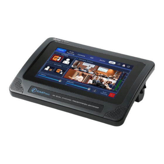
- Page 1 4K DUAL CHANNEL PRESENTATION SWITCHER iCAST MINI...
-
Page 2: Table Of Contents
3.1 F ....................10 RONT 3.2 R ....................11 3.3 L ....................13 CHAPTER 4 HOW TO CONNECT THE ICAST MINI AND YOUR CAMERA ..15 4.1 C -DVIP ............. 15 ONNECT NTERFACE NTRODUCTION 4.2 C -RS-422 & RS-232 ......16... - Page 3 Disclaimer of Product and Services The information offered in this instruction manual is intended as a guide only. At all times, Datavideo Technologies will try to give correct, complete and suitable information. However, Datavideo Technologies cannot exclude that some information in this manual, from time to time, may not be correct or may be incomplete.
-
Page 4: Fcc Compliance Statement
7. This product should only be operated from the type of power source indicated on the marking label of the AC adapter. If you are not sure of the type of power available, consult your Datavideo dealer or your local power company. -
Page 5: Warranty
Warranty Standard Warranty Datavideo equipment are guaranteed against any manufacturing defects for one year from the date of purchase. The original purchase invoice or other documentary evidence should be supplied at the time of any request for repair under warranty. -
Page 6: Three Year Warranty
DVD drives, Hard Drive, Solid State Drive, SD Card, USB Thumb Drive, Lighting, Camera module, PCIe Card are covered for 1 year. The three-year warranty must be registered on Datavideo's official website or with your local Datavideo office or one of its authorized distributors within 30 days of purchase. ... -
Page 7: Disposal
Disposal For EU Customers only - WEEE Marking This symbol on the product or on its packaging indicates that this product must not be disposed of with your other household waste. Instead, it is your responsibility to dispose of your waste equipment by handing it over to a designated collection point for the recycling of waste electrical and electronic equipment. -
Page 8: Chapter 1 Product Overview
Chapter 1 Product Overview Datavideo iCast Mini allows you to switch up to two 4K30 video inputs. Moreover, it provides Picture-in-Picture function. This touchscreen-operated device is suitable for classrooms, lecture halls, houses of worship, or any other situation that requires simple switching operations. -
Page 9: Chapter 2 System Diagram
Chapter 2 System Diagram... -
Page 10: Chapter 3 Connections
Chapter 3 Connections This section will show you the way for connecting the iCAST MINI 4K Dual Channel Presentation Switcher. For details, please refer to the following paragraphs. 3.1 Front View Interface Description Touch Panel Display This is the touch panel display for the iCAST MINI 4K... -
Page 11: Rear View
3.2 Rear View Description POWER Switch This is the power switch of the iCAST MINI 4K Dual Channel Presentation Switcher. DCIN 12V Power Interface Please connect the DCIN 12V power adapter in the package to the DC power interface. The connection can be secured by screwing the outer fastening ring of the DC In plug to the socket. - Page 12 MINI screen, the iCAST MINI will not output the HDCP video. VIDEO OUT-UVC This interface allows you to to connect the iCAST MINI to your laptop or PC by a USB type C to USB type A adapter cable for adopting the...
-
Page 13: Left View
RS-232/RS-422 The RS-232/RS-422 interface allows you to connect to an external RS- 232/RS-422 device. Please use an Ethernet cable to connect to an external RS-232/RS-422 controller. GPI OUT This port is not available and this function can be activated by the software update in the future. - Page 14 Description 3.5mm headphone monitoring interface This is the 3.5mm headphone monitoring interace for you to monitor the audio externally.
-
Page 15: Chapter 4 How To Connect The Icast Mini And Your Camera
The “Connect” interface of the Datavideo iCAST MINI allows you to connect your camera by the DVIP, RS-422 or RS-232 protocol. After the iCAST MINI is turned on, please tap the camera icon which is located at the top-right corner of the screen within the “Home”... -
Page 16: Connection Interface Introduction-Rs-422 & Rs-232
4.2 Connection Interface Introduction-RS-422 & RS-232 You can also use the RS-422 or RS-232 protocol to connect your iCAST MINI to your camera. After the iCAST MINI is turned on, please tap the camera icon which is located at the top-right corner of the “Home” interface to enter the “Connect”... - Page 17 1. Settings: Please tap this option to enter the “RS-422 Parameters” interface to set the parameters for several options including “BaudRate”, “Data Bits”, “Parity”, “Stop Bits” and “Flow Control”. Baudrate: Baudrate is the number of bits transmitted per second. There are several options including 9600, 19200, 38400, 57600 and 115200 for you to select.
- Page 18 Data Bits: Data Bits is the actual data bits in data transferred operation. There are several options including 5, 6, 7 and 8 for you to select. Parity: Parity is the easy way for checking serial communication errors. There are three options including Even, Odd and None for you to select.
- Page 19 Stop Bits: The stop bit is a signal sent at the end of a single packet communication. There are two options including “One Stop” and “Two Stop” for you to select. Flow Control: One side of the connection uses hardware or software to tell the other side when to start or stop transmitting data.
-
Page 20: Connection -Bydvip Protocol
After the connection is done according to the diagram above, the first thing is to press the power switch on the rear panel of the iCAST MINI to turn on its power. After that, you can see the initial screen which is shown in the following diagram. - Page 21 1. After the iCAST MINI turns on, the main interface of the iCAST MINI App which is shown in the following diagram will be shown. Please tap the camera icon which is shown at the top-right corner of the screen.
- Page 22 3. After the connected camera is found, the camera IP address will be shown on “Select Device” option. Please tap the “Select Device” option, and then select the IP address of the device that you want to connect. After that, tap the “Connect”...
-
Page 24: Connection -Byrs-422/Rs-232 Protocol
4.4 Connection-By RS-422/RS-232 Protocol If you want to connect your iCAST MINI and camera by the RS-422 or RS-232 protocol, please refer to the steps below. This chapter will take the RS-422 protocol as an example. 1. Please use an RJ-45 Ethernet cable to connect from the “RS-232/RS-422”... -
Page 25: Chapter 5 Icast Mini App Main Interface Introduction
3. PIP Mode (Front-PowerPoint Slide/Rear-Presenter): Please tap this button to show the two video input sources which are connected to the iCAST MINI as the “Front-PowerPoint Slide/Rear-Presenter” PIP mode to the external... - Page 26 4. PIP Mode (Front-Presenter/Rear-PowerPoint Slide): Please tap this button to show the two video input sources which are connected to the iCAST MINI as the “Front-Presenter/Rear-PowerPoint Slide” PIP mode to the external monitor. 5. Camera Preset 1/2/3/4: If the Camera Preset positions are set in advance, the thumbnails of the “CAMERA>POSITION1/2/3/4”...
- Page 27 6. CAM Button: This is the button for turning on or turning off the Auto- Tracking function. When the “CAM” button is shown in blue and the connected camera is a Datavideo Auto-Tracking supported PTZ camera, if you press the “CAM” button and the “CAM” button is shown in red, it means that the Auto-Tracking function of the camera is turned on.
- Page 28 If the “CAM” button is pressed when it is shown in red, the “CAM” button will become blue. At this time, the Auto-Tracking function will be turned off and the screen will switch to “Camera Preset” again. 7. Volume: This slider allows you to adjust the volume for monitoring 8.
- Page 29 “Scan in Network” button to search the camera which is set within the same LAN as the iCAST MINI. The “Select Device” option allows you to select the IP address of the camera that you want to connect.
-
Page 31: Camera
5.2 Camera 1. White Balance-Auto: Please press this button to apply the Auto White Balance settings. 2. White Balance-One Push: Please press this button to apply the One-Push White Balance settings. 3. White Balance-Manual: Please press this button to turn on the Manual White Balance function. - Page 32 4. SHUTTER: Please press this button to increase or decrease the shutter speed by pressing the “Shutter” adjustment slider or “+/-“ buttons which are shown in the following diagram. Please press the “Back” button to go back to the previous page. 5.
-
Page 33: How To Save The Position 1-4 Preset Positions
Please follow the steps below to save the Position 1-4 preset positions. Note: Due to that the iCAST MINI’s Graphic Key function is achieved by the RTSP stream function of the PTZ camera. So, you can use the Graphic Key function only when the DVIP protocol is selected to be the connection setting. - Page 34 3. Take the Position 1 as an example, once the Position 1 is pressed, the iCAST MINI will save the current image which is shot by the camera as the Preset Position 1. Moreover, it will use the current image which is shot by the camera to be the thumbnail of the Position 1 Preset.
-
Page 35: Pip
5.3 PIP Front-PowerPoint Slide/Rear-Presenter): Please press this 1. PIP Source ( button to show the two input video sources of the iCAST MINI by the “Front-PowerPoint Slide/Rear-Presenter” PIP mode to the external monitor. Front-Presenter/Rear- PowerPoint Slide 2. PIP Source ( ): Please press this “Front-... - Page 36 maximum sub-screen size of the PIP Mode can reach only the 80% of the main screen. 6. Color: This area provides many colors for you to select as the border color of the PIP sub-screen. Please tap your desired color to change the border color. 7.
-
Page 37: Audio
5.4 Audio 1. Channel Type: Please press the “Mono” button to set the audio channel type as “Mono”. And then please press the “STEREO” button to set the audio channel as “STEREO”. 2. Audio Delay(ms): You can press the “+”& “-“ buttons to increase or decrease the audio delay. -
Page 38: The Corrsponding Relationship Between Rear Panel's Xlr Audio
5.4.1 The Corrsponding Relationship between Rear Panel’s XLR Audio Interface and App UI’s Channel Type For the corresponding relationship between the iCAST MINI rear panel’s XLR Audio in interface and the App’s UI Channel Type, please refer to the table below. -
Page 39: Setup
5.5 Setup Please tap the gear icon which is located at the top-right corner of the “Home/Camera/PIP/Audio” pages. There are three pages for the “Setup” interface. - Page 40 1. Language: Please tap this option to select your desired language from English, Traditional Chinese and Simplified Chinese, and then please press the “Apply” button. Once the “Reset” button is pressed, it will resume to factory default. If you press the “Back” button, it will go back to the previous page. 2.
- Page 41 “Back” button, it will go back to the previous page. 4. Network: The factory default for the iCAST MINI is DHCP ON and it is no need for users to change the network related parameters. If your iCAST MINI is set as DHCP OFF, you can press this button to change the network related parameters manually.
- Page 42 GPI ON/OFF toggle switch. Note: Currently, this function is not available. 6. GPI Mode: The Pulse or Level trigger signal can be used for the iCAST MINI to trigger the function for starting or stopping the video recording. Note: Currently, This function is not available.
- Page 43 9. Shut Down: When this button is pressed, the screen of the iCAST MINI will be turned off in advance in order to protect the main unit. Please press the power button which is located on the rear panel of the iCAST MINI to turn off the power of the iCAST MINI.
- Page 44 10. Graphic Key: This option allows you to set the Graphic Key. Originally, the 4 preset positions in “CAMERA>Position 1/2/3/4” will capture the image which is shot by the camera to be the thumbnail of the four preset positions in the “Home”...
- Page 45 After that, you will enter the “Position Image” interface. We will take “Position 1” as an example, Please press the “Edit” button below the “Position 1”. After that, you will enter the “Graphic Key Sets” interface. Please use the right-arrow button which is located on the bottom of the page to go to other pages.
- Page 50 When you see the graphics that you want to apply it as a Graphic Key, please press the “Apply” button and then the Graphic Key is set successfully. At this time, you can see the Graphic Key that is selected by you from the “Home”...
- Page 51 About the firmware update procedure, please refer to the “Firmware Update” related chapters. 12. Screen Saver: In order to protect the screen of the iCAST MINI, this “Screen Saver” option allows you to set the wait time for activating iCAST MINI’s screen saver.
- Page 52 13. LCD Backlight: This “LCD Backlight” option allows you to set the brightness of the iCAST MINI LCD Monitor. You can press the “LCD Backlight” option, and then use the slider to set your desired LCD Monitor brightness percentage. Once it is set, please press the “Apply” button to finish the setting. Once the...
- Page 53 14. Camera Setting: Please tap this option to enter the “Camera Setting” interface. The “Camera Setting” option allows you to set several options including “Video Format”, “Camera Mirror Mode”, “Joystick Pan” and “Joystick Tilt”. For setting every parameter in the “Camera Setting” interface, you need to tap your desired option and then press the “Apply”...
- Page 54 Video Format: This option allows you to set your desired output video resolution.
- Page 55 Mirror Mode: This option allows you to select the camera output image to be “Vertical”, “Horizontal” or “Horizontal+Vertical”. Joystick Pan: This option allows you to set whether the camera lens moving direction is normal or reverse when the joystick is moving to the left side or right side.
- Page 56 Joystick Tilt: This option allows you to set whether the camera lens moving direction is normal or reverse when the joystick is moving to the up side or down side.
- Page 57 15. PTZ Stream Name: This option allows you to fill out the RTSP streaming name of the PTZ camera which is connected to the iCAST MINI. Due to that the “Graphic Key” function of the iCAST MINI is realized by the RTSP streaming of the PTZ camera.
- Page 58 “ON”, when you press the presaved 4 “Camera Preset” images to recall the presaved camera lens positions, the monitor which is connected to iCAST MINI’s Video OUT output interface will skip the image of the camera movement and it will show the preset position directly. If this option switches to “OFF”, the connected output device will show the process of the camera...
-
Page 59: Chapter 6 Firmware Update
Chapter 6 Firmware Update Please follow the steps below for updating the firmware of the iCAST MINI 4K Dual Channel Presentation Switcher. 1. Please download the latest software update file “icastmini_fwup_vx.x.x.x” from Datavideo official website’s iCAST MINI product pagehttps://www.datavideo.com/product/iCAST+MINI 2, Please unzip the downloaded firmware. - Page 60 Chapter 7. Dimensions Unit: mm...
- Page 61 Chapter 8. Specifications Model Name iCAST Mini Product Name 4K Dual Channel Presentation Switcher Video Standard 4K & HD Input: 3840x2160p: 30/29.97/25/24/23.98 1080p: 60/59.94/50/30/29.97/25/24/23.98 1080i: 60/59.94/50, 720p: 60/59.94/50 525i59.94 NTSC, 625i50 PAL Output: Video Format HDMI 3840x2160p: 30/29.97/25 1080p: 60/59.94/50/30/29.97/25/24/23.98 3840x2160p: 30/29.97/25...
- Page 62 Digital Embedded Input 2 channels, Output 2 channels Audio Support Audio Delay Up to 170ms Calibration A+V Switching Picture in Picture Effects Camera Control DVIP/ RS-422/ RS-232 Built-in Audio Mixer Firmware Update by USB Special Features 7" Touchscreen Display Chassis Unibody...
- Page 63 Dimension (LxWxH) 220 x 154 x 75 (mm) Weight 1.1 kg Power DC 12V 18.7W Operating Temp. 0~40 °C Range...
- Page 64 Service and Support https://www.datavideo.com/product/iCAST+MINI Sept.-15.2023 Ver:E1...