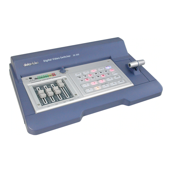
Datavideo se-500 Instruction Manual
Hide thumbs
Also See for se-500:
- Instruction manual (55 pages) ,
- Specifications (2 pages) ,
- Instruction manual (55 pages)
Table of Contents
Advertisement
Quick Links
Advertisement
Table of Contents

Related Manuals for Datavideo se-500


Summary of Contents for Datavideo se-500
-
Page 2: Table Of Contents
RS-232 ........................10 CONTROL ......................... 10 ALLY CONTROL MIDI ......................... 10 CONTROL 3. QUICK START ........................11 SE-500 F ........................ 11 RONT ANEL SE-500 R ........................14 ANEL ............16 ELECTING VIDEO INPUT FORMATS AND ADJUSTING AUDIO LEVELS .................... 16... - Page 3 Datavideo CG- CG-100 ......................... 40 Datavideo VGA to DV converter- PPT-100 .................. 40 Datavideo TLM-70D 7” TFT LCD ....................41 Datavideo DAC-6 DV to Analog (One way converter) ..............41 Datavideo BAC-03 Balanced-Unbalanced Audio converter ............42 Bi-Directional IEEE/1394 DV Format Repeater ................42 SE500 RS-232 R ..................
-
Page 4: Warnings And Precautions
AC adapter. If you are not sure of the type of power available, consult your Datavideo dealer or your local power company. 8. Do not allow anything to rest on the power cord. Do not locate this unit where the power cord will be walked on, rolled over, or otherwise stressed. -
Page 5: Warranty
• Certain parts with limited lifetime expectancy such as LCD Panels, DVD Drives, Hard Drives are only covered for the first 10,000 hours, or 1 year (whichever comes first). Any second year warranty claims must be made to your local Datavideo office or one of its authorized Distributors before the extended warranty expires. -
Page 6: Radio And Television Interference
Radio and Television Interference UNITED STATES: The equipment described in this manual generates and uses radio frequency energy. If it is not installed and used in accordance with the instructions in this manual, it may cause interference with radio and television reception. This equipment has been tested and found to comply with the limits for a Class B digital device, pursuant to Part 15 of the FCC Rules. -
Page 7: Introduction
1. Introduction Thank you for purchasing Datavideo’s SE-500 Digital Video Switcher. We hope you will be pleased with your purchase, and with what you can achieve with this advanced piece of technology. In order to get the most out of your new switcher, we recommend that you spend some time getting familiar with this manual, as it will describe in detail all the functions of this unit. -
Page 8: What Is A Switcher
The SE-500 has a full frame synchronizer (also known as a time base corrector or TBC) at its Main and Sub Source inputs in each channel (4 Total) to insure switches without distortion and smooth, well-regulated video at its output. -
Page 9: Installation, Connections, Set Up
2. Installation, Connections, Set up Some General Notes on Installation There are a few other things to be aware of when you are installing and integrating the SE-500. Please make sure you have read the Warnings and Precautions section. The SE-500 sends and receives analog signals except the RS-232, MIDI, and Tally. You need to be aware that cable lengths, impedance, crossing power cords, and adaptors might interfere with video transmission. -
Page 10: Connecting Video Sources
Connecting Audio Sources The SE-500 uses 2 kinds of plugs for audio connections: RCA and 1/4 inch jack plugs. There are lots of different names for these plugs. Fortunately for us all, they are not easily confused in the size and shape departments, so we’ll show you some pictures. -
Page 11: Audio Mixer
Needless to say, if you are outputting to a record deck, you should be able to easily monitor Connecting a Datavideo TLM-70D 7” TFT LCD the output of that device as well. preview video monitoring, page 41. Audio Mixer ... -
Page 12: Quick Start
3. Quick Start SE-500 Front Panel 1. Audio faders 9. Background color selection/Menu 2. Headphone 10. Border On/Off 3. Audio meters 11. T-Bar 4. Headphone Volume Control 12. Transition Effect preview 5. Video Effect: Quad 13. Main Video Source selectors 6. - Page 13 2. Headphones jack: accepts a stereo mini jack plug for stereo headphones. The headphone volume is controlled by the Headphone volume control (4.). 3. Audio Meters: LED style meters, which show the signal strength at the Audio Output. The signal measured is determined by the levels set with the Faders (1.).
- Page 14 : Transcoding is the act of changing video from one format to another, for example, from composite video to S-video. The SE-500 has been designed to perform transcoding, as part of its standard operating procedure. Select a video source on the Main Source Input bus, and it will be available at the Main Output in all formats, S-Video and Composite, simultaneously.
-
Page 15: Se-500 Rear Panel
S-Video (Y/C) input: takes a standard 4 pin S-video cable from the output of a VCR, camera, DVD player, etc. 2. Video Output. These ports carry the Main video output of the SE-500. a. Composite video out: BNC connector typically connected to a program monitor. - Page 16 10. Power: Switches the unit On / Off. 11. DC Input: connect the power supply that came with the SE-500, and only the power supply that came with the SE-500, here, and plug the other end into an electrical outlet, preferably on a surge suppressor (to protect the SE-500 from random power spikes that can fry its delicate insides).
-
Page 17: Selecting Video Input Formats And Adjusting Audio Levels
S-Video to Composite, and vice versa. However, if you connect both S-Video and Composite inputs on the same Channel, the SE-500 will automatically select the S-Video as main input source. -
Page 18: Effects
Effects There are two places on the SE-500 where you can add effects: in the Transition Effects section (15.) and in the Video Effects section (5-8.). Some of these work on a single source, and some need two or four sources to work. -
Page 19: Controls And Operations
The frozen image is a function of how the time base corrector (TBC, a.k.a. frame synchronizer) works. The SE-500 has a TBC at the Main Video Source and the Sub Video Source input on each channel. Their purpose is to stabilize the video signals as they come into the switcher, and to synchronize their timing so that they can be switched and otherwise combined with no disruption to the video signal. - Page 20 On the top of screen you can see 4 different numbers, each represent the input channel from the SE-500 rear panel. On the left side of this ±0 ±0 ±0 ±0 Brightness section are the 4 controls (Brightness, Contrast, Color, and Tint (NTSC only)).
-
Page 21: Menu
Component output signal. If you use a MIDI keyboard in live concerts, you will be amazed what the SE-500 can do. Go to “Remote Control”, use + or - to change the setting from RS-232 to MIDI. Press “BACKGROUND” again, select the desired MIDI channel you wish to use. - Page 22 Three faders on the left represent the input volumes (CH-1, CH-2, AUX), which determine what signals are present at the Main Output. If any of the faders are all the way down, there will be no audio from that input channel heard at the output.
-
Page 23: Using Transitions
5. Using Transitions The SE-500 can do 3 kinds of transitions: cut, fade, and wipe. The cut is a simple switch from one input source to another, and can be accomplished by selecting a source on the Main Source Bus, and then selecting a second one. -
Page 24: List Of Transitions And Parameters (Suitable For Photocopying)
List of transitions and parameters (suitable for photocopying) Wipe (works in conjunction with Border controls): Block wipe from center to full screen. Right angle wipe on, upper right to lower left Right angle reveal, lower right to upper left Right angle wipe on, upper left to lower right Right angle reveal, lower left to upper right Horizontal wipe, top to bottom Horizontal wipe, bottom to top... - Page 25 Vertical wipe, middle to left and right Horizontal wipe, middle to top and bottom...
-
Page 26: Using Effects
6. Using Effects The SE-500 is capable of producing a wide variety of digital effects. These falls into 2 categories: single channel and dual channel effects. Single channel effects are produced on the source selected in the Main Video Source bus and need no second video input. -
Page 27: Effects: Picture In Picture
button. You could also select different sources for the left window by pressing 1-4 channel on Main source or pressing 1-4 channel on Sub source for right window. Effects: Picture in Picture The Picture in Picture effect puts the selected Sub Video Source in a window on the Main Video Source. -
Page 28: Sample Applications
7. Sample applications We figured, being practical minded, that the best way to show off what the SE-500 can do is to give you some examples of how it could be used in real life situations. Each example refers to a block diagram for set up and connections. -
Page 29: Live Conference
Live Conference In this second example we see a typical conference set up. There are two cameras to handle the speaker and the overview, with audience reaction or other action on the stage. Both cameras are analogue, but by adding a DAC 6 to any of the channels it would be possible to use a DV camera. -
Page 30: Live Event Mixing: Club Vj / Concert
Live Event Mixing: Club VJ / Concert In our final example we are looking at a typical V.J. set up. Increasingly in clubs video images are used to add to the overall effect and atmosphere, they are combined with light displays and other audio / visual effects. -
Page 31: Using Se-500 With Cg-100 For Titles/Graphics/Logos Overlay
Using SE-500 with CG-100 for Titles/Graphics/Logos overlay Using YUV output (with a breakout cable) on SE-500 to communicate with a PC with Decklink SP CG overlay card and CG-100 CG software to perform a text overlay for the output video. -
Page 32: Troubleshooting
Check that the power supply is plugged into the SE 500, and to a suitable mains outlet, and that it is switched on. Move the SE-500 to a cooler location and allow the unit time to cool off before powering on again. No image at output Incorrect video input format selection Check that the output format is set correctly for S (Y/C) or Component. -
Page 33: Appendix
9. Appendix Glossary of Terms Analog video: a video signal that is recorded and played back using changes in magnetic levels recorded a tape or disk, e.g., the video we see when we watch a VHS videocassette. Animation: a video or film sequence that gives the illusion of motion by presenting a series of images or photographs. - Page 34 Impedance: A.C. resistance in an electrical circuit, measured in Ohms. Impedances must be matched in audio circuits to avoid distortion and the introduction of noise. Key: 1) in lighting, short for key light, the principle (usually brightest) light used to illuminate the main subject;...
- Page 35 Vector scope: a test instrument for displaying color hue and saturation in a video signal used to aid in color correction. Waveform monitor: a test instrument which shows a graphical representation of the luminance levels of the video waveform, used, in conjunction with a vectorscope, as an aid in color and image correction and video system set up.
-
Page 36: Tech Notes
Tech Notes Books are written about many of the topics below, large and complex books. Look for them if you want more information than what we have presented here. What we want to do here is to provide a bit more in depth information, deeper background, on some relevant topics, and give you a framework for further technical investigations. -
Page 37: Monitor Calibration (Procedures, Test Patterns/Bars)
One important way, perhaps the most important way, to make sure that your video really looks as good on other monitors as it does on yours is to monitor the video with a properly calibrated monitor of as professional-level quality as you can afford. See below for some methods to calibrate monitors. And it goes without saying that you should have dependable, high quality audio monitoring as well, either through headphones or speakers you can trust. - Page 38 SE-500. For each input you plan to be using, have a valid signal and adjust the Color Processor controls on the SE-500 in this order: 1.
-
Page 39: Specifications
Specifications Video Formats Analog Y/C, Composite CCIR601 NTSC and PAL (PAL and NTSC are separate models) Video Inputs 4 – S (Y/C), Composite Video Output 1 – Quad Video source monitoring (Composite) 2 – Composite 1 – S (Y/C) 1 – Component (With breakout cable, it uses the S (Y/C), and one Composite output.) Audio Inputs 1 –... - Page 40 Audio 20 to 20 KHz +/-3dB Audio THD <0.1% Dimensions W x D x H 15.75" x 10.5" x 3.25" (Approx) 400mm x 265mm x 83mm (Approx) Weight 5.5 lb, 2.2 Kg Power Input: DC 12V, 1.5A (11W)
-
Page 41: Useful Accessories From Datavideo
Datavideo CG-100 THE FIRST AFFORDABLE SDI CG SOLUTION LIVE SDI TITLE / GRAPHIC / LOGO OVERLAY CG-100 can be used in any SDI or YUV input switchers. It can be also used in SE-500 via YUV output interfaces. SDI overlay offers the best, broadcast quality, CG solution in the industry today. -
Page 42: Datavideo Tlm-70D 7" Tft Lcd
VCR, VHS and CD player for a perfect presentation. Datavideo TLM-70D 7” TFT LCD Datavideo TLM-70D is a 7” TFT LCD monitors, 3U height design with TLM-70JF you can easily to insert it on standard 19" rack cabinet. NTSC/PAL video format... -
Page 43: Datavideo Bac-03 Balanced-Unbalanced Audio Converter
20 meters for cable runs of up to 200 meters One channel DV repeater (VP-314) 20/10 meter DV cable P/N: 2066/1066 One input to five channels output DV-DA (VP-332) Please check website (www.datavideo.com) for the most up to date list, descriptions, and pricing of accessories for the SE-800. -
Page 44: Se500 Rs-232 Remote Control Command
SE500 RS-232 Remote Control Command VER: 1.03 Release date: 2006/02/22 1. Physical layer Control output format: RS-232C Communication rate: 57600 BPS Data format: 8 bits serial, LSB first, 1 start bit, 1 stop bit, odd parity Must delay 100uSEC between 2 bytes 2. - Page 45 1) The command group 05h (base 16) = SE500 control command 2) The operated refer to section 4. 3.2 Return data format 10th 11th … Command parameter parameter parameter parameter parameter parameter parameter … Status 1) The command status 05h=SE500 control command status 2) The parameter refers to section 6.
- Page 46 15h= key_left_bottom_block (wipe) 16h= key_top_block (wipe) 17h= key_bottom_block (wipe) 18h= key_right_block (wipe) 19h= key_left_block (wipe) 1ah= key_horizontal (wipe) 1bh= key_vertical (wipe) 20h= key_border_on 22h= key_background_color 24h= key_speed* 26h= key_PIP 28h = key_speed1** 29h = key_speed2** 2ah = key_speed3** 3bh = key_menu 3ch = key_up 3dh = key_down 3eh = key_left...
- Page 47 2xh = SPEED_3 4) The effect No. The value from 0 to 99(63h) Fade effect No. = 0 Wipe effect No.= 0 to 10 Quad effect No.= 0 POP effect No. = 0 to 1 PIP effect No.:bit3 to bit0= x0h to x4h (position) Bit4=0=big size, bit4=1=small size Bit5=0=not shift, bit5=1=shift to close center.
- Page 48 7. EXAMPLE 1) PC control SE500, key command = key_take= 0fh a.) The command stream = F0h,32h,0eh,05h,01h,0fh,,30h,34h,ffh Header=F0h ID=32h Length = 9 bytes=09h Command group=05h Command mode=normal control code=01h Control key code=key_take =0fh checksum= (f0h+32h+09h+05h+01h+0fh) = 40h checksum_low =00h+30h = 30h checksum_high=04h+30h = 34h END =ffh b.) SE500 return data,...
-
Page 49: Se500 Midi Remote Control Command
SE500 MIDI Remote Control Command VER: 1.00a Release date: 2005/06/03 1. Physical layer Follow the MIDI SPEC. 1.0 Communication rate: 31250 BPS Data format: 8 bits serial, LSB first, 1 start bit, 1 stop bit, none parity 2. Data link layer 2.1 Control messages = MIDI Channel voice messages * Received only if Note Mode is ON * The input of each channel is selected. - Page 50 SUB D key PIP key SUB BG key Freeze key Preview key TAKE key MAIN A key Background color key MAIN B key Border key MAIN C key MAIN D key Speed _1 key MAIN BG key Speed_ 2 key Change Speed key Speed_ 3 key 4.
-
Page 51: Se500 Tally Pin Outs Cross Reference
SE500 Tally Pin Outs Cross Reference VER: 1.00 Release date: 2005/07/07 LED A3 = pin 1 = 1R (Main1) LED A2 = pin 2 = 1G LED A1 = pin 3 = 1Y (Sub1) Green Ground = pin 4 = GND Video Red LED Yellow LED... -
Page 52: Service And Support
Service and Support...