Table of Contents
Advertisement
Quick Links
Download this manual
See also:
Instruction Manual
Advertisement
Table of Contents

Related Manuals for Datavideo SE-2000


Summary of Contents for Datavideo SE-2000
- Page 1 Dear Digital Video Switcher SE-2000 INSTRUCTION MANUAL Rev250110 www.datavideo-tek.com...
-
Page 2: Table Of Contents
SE-2000 Configuration Utility .................... 20 Storing New Logos ......................20 Setting up a Luma Key overlay with PowerPoint .............. 21 HD-SDI Cabling Advice ..................... 22 Optional Datavideo Accessory Items for the SE-2000 ............23 Specifications ........................24 Service and Support ......................25... -
Page 3: Warnings And Precautions
7. This product should only be operated from the type of power source indicated on the marking label of the AC adapter. If you are not sure of the type of power available, consult your Datavideo dealer or your local power company. -
Page 4: Warranty
Certain parts with limited lifetime expectancy such as LCD Panels, DVD Drives, Hard Drives are only covered for the first 10,000 hours, or 1 year (whichever comes first). Any second year warranty claims must be made to your local Datavideo office or one of its authorized Distributors before the extended warranty expires. Disposal For EU Customers only - WEEE Marking This symbol on the product indicates that it should not be treated as household waste. -
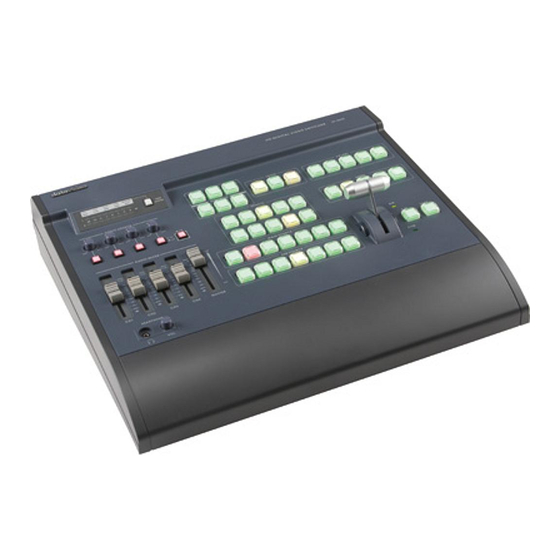
Page 5: Product Overview
The brand new SE-2000 switcher not only meets your request for true full 1920 x 1080 HD quality, but also provides an array of simple-to-operate features, including up to 14 pre-stored logos, digital clock display, five user setup, DVI-D connection for use with presentation software and easy titling, and many more features. -
Page 6: Connections & Controls
Connections & Controls Keyboard 1. Audio mixer 7. Transition Speed 2. Audio input selectors / Level Controls 8. Transition Effects 3. Audio meters 9. CUT & TAKE 4. Menu and Controls 10. T-Bar 5. Logo & Clock Selection 11. Main and Sub Source selection 6. -
Page 7: Audio Mixer
Audio Input Source Selectors and Level Controls This section of the SE-2000 controls which audio input channel (CH1~CH4) will be sent to the Audio Bus and its associated Fader. This row of audio channel selection buttons has LEDs built in to show which input channel is active. -
Page 8: System Configuration Menu
System Configuration Menu Press the Menu button in the SE-2000 function section to enter the System Configuration Menu. Press the up, down, left, and right arrow buttons to navigate the menu options and to change values. Use the ENT button to save and confirm any setting that has been amended. -
Page 9: T-Bar
1 to 2mm. 8. Press the TAKE key. The AIR LED will light up. 9. Press the SET key to return to the SE-2000 to operational mode. WARNING: If you do not follow the T-Bar calibrating steps correctly the T-Bar may work incorrectly. -
Page 10: Rear Panel
INPUT 4 MODE (Page 15). 3. DVI-D IN DVI-I Signal Input (Digital Input 5). 4. TALLY Tally out socket. This supplies tally light information to the Datavideo ITC-100 system (not supplied). 5. RS-232 9-pin serial port standard RS-232 interface. Connect PC to update firmware, Logos or Mixer Configuration. - Page 11 Supports two channels XLR Balanced Audio output. 12. AUDIO IN The SE-2000 supports four XLR Balanced Audio Input channels. There are two kinds of switches under AUDIO IN: LINE/MIC switch is used to set the audio as LINE in or MIC in. When LINE in is selected please also set the 48V ON/OFF switch to OFF in order to prevent burn-out damage to the circuit.
-
Page 12: Multi Preview Output
Multi Preview Output The Multi Preview output on the rear of the SE-2000 should be connected to a compatible 19” to 24” LCD monitor via a DVI-D cable connection. This Multi Preview display output can be run at 1080i or 720p [60Hz]. -
Page 13: Main Source And Sub Source Rails
Main Source and Sub Source Rails The Main Source Rail shows the active channel, this is the Live output. The active channel will also appear as the Program Output (PGM). You can immediately switch or CUT from one input channel to another directly on the Main Source Rail, you will see the PROGRAM Output switch as you press different keys along this rail. -
Page 14: System Configuration Menu
System Configuration Menu Menu and Navigation Press the MENU button in the Function section of the SE-2000’s keyboard to enter the System Configuration Menu. The menu will be displayed on the SE-2000’s Multi Preview output as below. Press the UP, DOWN, LEFT and RIGHT arrow buttons to highlight or select a menu option. Then use the UP and DOWN arrow buttons to change the value of the selected item or option. -
Page 15: Pip Setting
If you want to enable the PIP function, you must first press the SET key in the PIP / KEY section of the SE-2000 keyboard, then press the PIP PVW key and then select the Sub Source channel required for the PIP window. -
Page 16: Mode Setting
Press the arrow buttons to select an item and press the ENT to confirm the setting. This mode is used to return the SE-2000 BASIC profile (USER 0) to its factory default settings. If the BASIC profile is changed then any USER profiles (1 ~ 5) linked to BASIC will also be changed. -
Page 17: Background
Press the arrow buttons to select an item and press the ENT to confirm the setting. This mode is used to set the clock within the SE-2000. The current Clock value is displayed in between the PREVIEW and PROGRAM windows of the Multi... -
Page 18: Audio Inputs And Levels
NOTE: Audio cannot be de-embedded by the SE-2000 from a HD-SDI input and Audio will not be embedded into the SE-2000’s HD-SDI PGM outputs. For ideas on how best to do this before and after the SE-2000 mixer see Example SE-2000 Set Ups (Page 17). -
Page 19: Example Se-2000 Set Ups
Example SE-2000 Set Ups... -
Page 20: Se-2000 Configuration Utility
Once downloaded, run the install wizard and follow the on-screen prompts. The installation will leave an Icon on the PC desktop as above. With the SE-2000 connected to the PC via an RS-232 cable, the initial utility screen will be displayed as above, when the program is launched. -
Page 21: Setting Up A Luma Key Overlay With Powerpoint
Setting up a Luma Key overlay with PowerPoint The SE-2000 has 5 inputs. Input 5 is DVI only and this can be used to connect a DVI-D cable from a computer’s monitor/graphics card. The PC graphics card will need 2 connections 1 for the PC monitor and a spare DVI-D connection to go to input 5 on the SE-2000. -
Page 22: Hd-Sdi Cabling Advice
SDI signal received. The signal is attenuated because part of it is reflected back and does not make it to the receiver (SE-2000 for example); it is also distorted because the reflected signal mixes with the original signal causing it to distort as well as adding to the noise floor. -
Page 23: Optional Datavideo Accessory Items For The Se-2000
Datavideo have a number of accessory products which will allow you to get the most from your new SE-2000. Please speak to your local dealer or visit the website for your local Datavideo office for more details on these and other products. -
Page 24: Specifications
Specifications • 4x BNC connector for HD -SDI input Inputs • 2x DVI connector for DVI-D input (1x DVI-D input is collective with SDI#4 channel) • 2x HD-SDI output, 1x HD-YUV output, and 1x DVI-D output Outputs • HD (1080/50i - 1080/60i - 1080/59.94i - 720/50p - 720/60p - 720/59.94p) Video Input •... -
Page 25: Service And Support
It is our goal to make your products ownership a satisfying experience. Our supporting staff is available to assist you in setting up and operating your system. Please refer to our web site www.datavideo-tek.com for answers to common questions, support requests or contact your local office below.