Datavideo SE-900 Instruction Manual
Digital video switcher
Hide thumbs
Also See for SE-900:
- Product manual (36 pages) ,
- Instruction manual (30 pages) ,
- Instruction manual (82 pages)
Table of Contents
Advertisement
Quick Links
Advertisement
Table of Contents

Related Manuals for Datavideo SE-900


Summary of Contents for Datavideo SE-900
- Page 1 SE-900 Digital Video Switcher Instruction Manual www.datavideo-tek.com Rev 150109...
-
Page 2: Table Of Contents
Table of contents Warnings and Precautions --------------------------------------------------------------------------------- 6 Warranty ---------------------------------------------------------------------------------------------------------- 7 Disposal ------------------------------------------------------------------------------------------------------------ 7 Packing List ------------------------------------------------------------------------------------------------------ 7 Introduction ------------------------------------------------------------------------------------------------------- 8 Features ----------------------------------------------------------------------------------------------------------- 8 Overview ----------------------------------------------------------------------------------------------------------- 9 Connections & Controls ---------------------------------------------------------------------------------- 10 Base Unit ------------------------------------------------------------------------------------------------- 10 I/Os --------------------------------------------------------------------------------------------------------- 11 Control Panel -------------------------------------------------------------------------------------------- 13 LCD Display ----------------------------------------------------------------------------------------- 14 I/O Card Options ---------------------------------------------------------------------------------------- 15 Fitting an I/O Card -------------------------------------------------------------------------------------- 18... - Page 3 11. Store & Recall --------------------------------------------------------------------------------------- 36 12. Update Firmware ----------------------------------------------------------------------------------- 36 Operation ------------------------------------------------------------------------------------------------------- 38 Powering On --------------------------------------------------------------------------------------------- 38 Multi Image Preview ------------------------------------------------------------------------------------ 39 Overview --------------------------------------------------------------------------------------------- 39 Setting the Output Type -------------------------------------------------------------------------- 40 Modifying the Layout ------------------------------------------------------------------------------ 40 Top or Bottom View ----------------------------------------------------------------------------- 40 Setting the size of the Output ---------------------------------------------------------------- 40 Setting the Noise Filter ------------------------------------------------------------------------ 40 Setting the Border Brightness --------------------------------------------------------------- 41...
- Page 4 Setting the Transition -------------------------------------------------------------------------- 56 Mosaic ------------------------------------------------------------------------------------------------ 57 Paint -------------------------------------------------------------------------------------------------- 58 Strobe ------------------------------------------------------------------------------------------------- 58 B/W (Monochrome) ------------------------------------------------------------------------------- 59 Colour Correction ------------------------------------------------------------------------------------- 59 Brightness Contrast Saturation ----------------------------------------------------------------- 60 RGB Correction ------------------------------------------------------------------------------------ 60 AGC Automatic Gain Control ------------------------------------------------------------------- 61 Chroma Keying ---------------------------------------------------------------------------------------- 62 Overview --------------------------------------------------------------------------------------------- 62 Setting up a Chroma Key Channel ------------------------------------------------------------ 63 Chroma Keying ------------------------------------------------------------------------------------- 67...
- Page 5 Reset ------------------------------------------------------------------------------------------------------ 82 PAL - NTSC ---------------------------------------------------------------------------------------------- 83 Updating Firmware ------------------------------------------------------------------------------------ 84 Checking Firmware Revisions -------------------------------------------------------------------- 86 Specification --------------------------------------------------------------------------------------------------- 87 Optional Datavideo Accessory Items for the SE-900 ------------------------------------------------- 88 Service and Support ---------------------------------------------------------------------------------------- 89...
-
Page 6: Warnings And Precautions
7. This product should only be operated from the type of power source indicated on the marking label of the AC adapter. If you are not sure of the type of power available, consult your Datavideo dealer or your local power company. -
Page 7: Warranty
Equipment that fails after the warranty period, has been operated or installed in a manner other than that specified by Datavideo, or has been subjected to abuse or modification, will be repaired for time and material charges at the Buyer’s expense. -
Page 8: Introduction
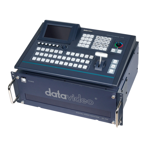
Introduction The Datavideo SE-900 is an 8 Channel Video Mixer / Switcher. The modular design allows any combination of different input cards to be used. Up to 8 input cards can be fitted, options available are SDI, DV, Analogue (CV / Y/C / Component (YUV)), and DVI. -
Page 9: Overview
The Control Panel is a desk mount unit which attaches to the Base Unit via a single (Sub-D 9 pin) cable. The Control Panel has all of the controls, and a series of set up menus for configuring the SE-900. -
Page 10: Connections & Controls
Base Unit Front Panel The front panel of the SE-900 base unit has a ventilation panel; to prevent overheating please ensure that adequate airflow is provided. The main power On / Off switch is in the upper left corner of the Base Unit front panel. If power is connected the On /Off switch will light up when the SE-900 is switched on. -
Page 11: I/Os
Chroma Key - adds a 4 Channel Chroma Keyer. With this you can key green, blue or luma, to create overlay effects External Sync - Allows the SE-900 to be synchronised to an external source. As standard the SE-900 can synchronise all eight channels internally, so no genlock is necessary, but if you want to synchronise... - Page 12 Slot 9 Chroma Key The Chroma Key card adds a 4 channel chroma keyer to the SE-900. It is able to key green, blue or luminance, according to the effect you’re trying to create. Each of the four channels are independent, so you could have two green keys, a blue key on the third channel and luma key on the fourth.
-
Page 13: Control Panel
Control Panel The Control Panel controls every aspect of the SE-900. It is connected to the Base Unit via a single Sub D 9 Pin Cable. The supplied cable is 1.2m in length, it would be possible to use a longer cable if required. -
Page 14: Lcd Display
The Cued Source - PST The Live Source - PGM The LCD Display will also show the System Set Up Menus, which are used to configure the SE-900. For more information on the System Set Up Menus please see Set Up Menus... -
Page 15: I/O Card Options
I/O Card Options Slots 1 ~ 8 Analogue Video Input Selectable Composite Video, S-Video (Y/C) or Component input, also provides a composite monitor output. Slots 1 ~ 8 DV Input As well as providing DV in, the DV Input card de-embeds the DV audio and provides it as balanced audio output via mini XLR Cables. - Page 16 SDI Overlay This card provides an SDI loop through output for adding an SDI character generator. You could use a Datavideo CG-100 / CG-350 to add text, graphics, logos etc as a downstream key. The card can also be used to input a signal for the SE-900 internal DSK.
- Page 17 Slot 9 Chroma Key The Chroma Key card adds a 4 channel Chroma Keyer to the SE-900. It is able to key green, blue or luminance, according to the effect you’re trying to create. Each of the four channels are independent, so you could have two green keys, a blue key on the third channel and Luma Key on the fourth.
-
Page 18: Fitting An I/O Card
Fitting an I/O Card The SE-900 has been designed to allow I/O Cards to be easily added or changed to suit your requirements. The SE-900 is supplied with blanking plates, which cover the unused slots. To remove the blanking plates simply unscrew the thumb screws at the top and bottom of each plate and it will pull away. - Page 19 When fitting a card please take anti-static precautions. The minimum anti static precaution would be to ensure that you are touching the SE-900 Base Unit while fitting the card, ideally wear an anti static wristband, or ensure that you are properly grounded by any other means. ESD damage to cards is rare but will not be covered by warranty if it occurs, so be careful.
-
Page 20: Setting Up
Setting Up Power Connections There are two power connections to look at on the SE-900, one on the base unit and the other on the Control Panel. Base Unit Connect the supplied 12V 10A power supply to the DC In on the Base Unit. The power supply should be connected to a... -
Page 21: Monitor Connections
Monitor Connections If space is at a premium it is possible to operate the SE-900 with just one monitor. The Multi Image Preview can provide images from all eight inputs plus next source preview (PST) and output (PGM). It will also supply basic tally information by highlighting the live source with a red border, and the cued source with a yellow border. - Page 22 Card also has a composite Next Source (PST) and Program (PGM) output. Using these monitoring outputs it is possible to connect ten monitors, one for each input plus one for PST and one for PGM, to the SE-900. This is an example configuration. Illustrated are two Datavideo TLM-404 (4 x 4” Monitors), and one Datavideo TLM-702 (2 x 7”...
-
Page 23: Video Connections
Video Connections Video Inputs The SE-900 can be configured to have an endless combination of different video inputs. This unlikely illustration shows examples of the different input types that could be connected. The analogue inputs can be set to CV(Composite), Y/C (S-Video), YUV (Component) in the Video Input Set Up Menu - see Set Up Menus - Video In for details. - Page 24 Video Outputs The SE-900 has multiple video outputs. It is possible to output SD-SDI, DV, Component (YUV (Y Pb Pr)) , Composite and S-Video. The SDI and DV outputs can both have embedded audio. The SDI Card also has a Black Burst Output to provide synchronisation to other devices.
-
Page 25: Audio Connections
For setting up the delay please see Set Up Menus - Audio Delay and Audio Delay Circuit Depending on the type of video inputs and outputs the SE-900 will delay the video stream by up to 4 frames, so the audio needs to be delayed by the same amount. - Page 26 Delay Times according to Video I / O Types Input PGM output Frame Delay 1 frame S-Video 1 frame 1 frame 2 frames 1 frame Not Available at time of printing 2 frames S-Video 2 frames 2 frames 3 frames 2 frames Analogue Video 1 frame...
- Page 27 You could take a feed from one of your DV or SDI Video Inputs and feed that directly to the Audio Delay Circuit. (In this example DV Input (Slot 8)) You could take audio out from each of your DV and SDI Video Inputs, feed them all to an audio mixer, and then take the balanced audio mixer feed and put it through the Audio Delay Circuit.
-
Page 28: Powering On
Powering On To switch the SE-900 on there are two power switches, one on the front of the Base Unit, and the other on the rear of the Control Panel. Base Unit On / Off Switch Control Panel On / Off Switch Make sure that the 12V 10A power supply is connected to the Base Unit, and to a suitable AC Mains outlet. -
Page 29: Set Up Menus
Set Up Menus Overview The SE-900 is set up by a series of menus. Once the settings have been made they are stored in the system, so it is only necessary to make the settings once. The System Set Up Menus appear in the LCD Display of the Control Panel. - Page 30 This example is one of the more complex menus “Chroma Key”. You can see that it is two pages long. The principles used here apply to all of the System Set Up Menus. To open the Chroma Key Menu, press the Setting Key to call up the System Menu Display, highlight 1.
-
Page 31: Chroma Key
This section will cover the Set Up Menus in numerical order, as they appear in the SE-900. The settings will also appear in more detail elsewhere in the instruction manual. For example, 1. Chroma Key will also appear in greater detail in Operation - Chroma Keying. -
Page 32: Video In
14 - 17 WINDOW X These set the working area of the keyer. Also known by many users as “Garbage Matte”. If your back cloth does not fill the whole shot, E.G. when working with wide angle shots, you can adjust out the non keyable background areas. The settings are based on the longitude and latitude of the video frame, which is 720 x 576, so 000 - 720 describes the position from fully left to fully right, and 000 - 576 describes the position from top to bottom. -
Page 33: Video Out
MODE_1 = Windows XP PC MODE_2 = Windows 2000 PC MODE_3 = MAC MODE_0 = CAMCORDER / DV DECK / Datavideo DN-300/400/500 2: V. OUT 7.5 IRE ON / OFF Sets the IRE (black level) to 0 or 7.5. This is only necessary for NTSC. -
Page 34: Cg Input
9: LOGO2 POSITION X 1 - 147 Sets the position of LOGO 2. 0 is fully to the left 147 fully to the right 10: LOGO2 POSITION Y 1 - 119 Sets the position of LOGO 2. 1 is at the top 119 is at the bottom. -
Page 35: Multi. Image
7. MULTI. IMAGE Title Values Description Sets the type of output 1: OUTPUT TYPE YUV / CV 2: IMAGE POS. TOP / BOTTOM Sets the appearance of the Multi Image screen (PST / PGM at the top or the bottom of the layout). -
Page 36: Store & Recall
USER_1 - USER_3 Stores all current settings to one of three user memories. All settings and preferences are stored. 4: RESET ALL Press RESET for 2 SEC Resets the SE-900 to factory defaults. 12. UPDATE FIRMWARE Title Values Description 1: NORMAL (RECOMMENDED) - Page 37 2: DETAIL 1: VIN_1 Highlight to update Video Input Board 1 software 2: VIN_2 Highlight to update Video Input Board 2 software 3: VIN_3 Highlight to update Video Input Board 3 software 4: VIN_4 Highlight to update Video Input Board 4 software 5: VIN_5 Highlight to update Video Input Board 5...
-
Page 38: Operation
Operation Powering On To switch the SE-900 on there are two power switches, one on the front of the Base Unit, and the other on the rear of the Control Panel. Base Unit On / Off Switch Control Panel On / Off Switch Make sure that the 12V 10A power supply is connected to the Base Unit, and to a suitable AC Mains outlet. -
Page 39: Multi Image Preview
Multi Image Preview – Overview The SE-900 has a Multi Image Preview Output. This shows all eight inputs plus the PST and PGM selections. The Multi Image Preview Board can output either YUV Component or Composite Video. If you have the option Component will always give a clearer picture. -
Page 40: Setting The Output Type
The Video Noise Filter can improve this and give a more viewable preview. N.B. This does not affect the overall output of the SE-900 it is just softening the preview. To alter the Noise Filter Settings, press the Setting Key, to call up the Set Up Menus, highlight option 7. -
Page 41: Setting The Border Brightness
Setting the Border Brightness The intensity of the white border surrounding each preview window can be adjusted to your own preference. To alter the Border Brightness, press the Setting Key, to call up the Set Up Menus, highlight option 7. MULTI. -
Page 42: Control Panel
Control Panel has all of the controls, and a series of set up menus for configuring the SE-900. When you power up the SE-900 the keys on the control panel will light up. It should look something like this: You will notice that the CK SYNC, and CK Keys on the Main and Sub Source Rails do not light up during normal operation, this is intentional. -
Page 43: Adjustments And Setup
Adjustments and Set Up All of the settings for the SE-900 are controlled from the LCD Display and the Adjustment Keys / Knob The LCD display will display the status of the SE-900 during operation, and will display the Set Up Menus during Set Up. -
Page 44: Main Source And Sub Source Rails
Main Source and Sub Source Rails The Main Source Rail shows the active channel, this is the Live output. The active channel will appear as the Program Output (PGM). You can switch from one channel to another directly on the Main Source Rail, you will see the PGM Output switch as you press different keys along the rail. - Page 45 The Multi Image Preview Screen will show the Main Source with a red border and sub-source as a yellow border. The Main Source will appear in the PGM window, and the sub source will appear in the PST window. In this example Channel 2 is Live and Channel 3 is Cued When you press the TAKE Key, or move the T-Bar you will see the PGM and PST channels swap over.
-
Page 46: T-Bar And Take Keys
T-Bar and Take Keys The T-Bar and the Take Keys enable you to manually or automatically perform transitions. The T-Bar is manual way to perform a transition. The T-Bar travels from top to bottom, or bottom to top. The active transition will be performed at the same speed as the movement of the T-Bar. -
Page 47: Effects And Transitions
Effects and Transitions The SE-900 features a variety of different Effects and Transitions which can be set up as presets, or performed manually. Effects The Effects of the SE-900 are PIP (Picture in Picture), Mosaic, Paint, Strobe, B/W (Monochrome). Additional options within the effects panel are CK (Chroma Keying),... - Page 48 Status Display Transitions The SE-900 features 14 programmable wipe patterns and an A/B dissolve. All wipes can have optional colour borders applied, and each can be set to one of six preset speeds. The active transitions, speed, border width and colour is displayed in the Status Display.
-
Page 49: Joystick
Joystick The Joystick is used in conjunction with several features. It is used to adjust the RGB colour settings of the video inputs, and to position mosaic or PIP effects. Used to set RGB colour correction and to position PIP and Mosaic effects RGB - (Red / Green / Blue) sets the Joystick to colour correction mode for Video Input setting POS CNTL - Position Control sets the Joystick to positioning mode for PIP and Mosaic effects Preset Effects... -
Page 50: Level / Speed
Each preset will store an effect or transition together with the speed, border setting and screen position, where applicable. To access presets F1 to F5 simply press the respective key. To access presets F6 to F10 first press the F6-10 key, so that it lights up as active and then press F1 for F6, F2 for F7 and so on. -
Page 51: Modifying The Appearance Of The Control Panel
Modifying the appearance of the Control Panel There are a number of settings which alter the way the Control Panel looks; you can set these to your own preference, or to suit the environment you’re working in. Press the Settings Key to call up the Set Up Menus and highlight option 10. CONTROLLER. Press the Enter Key to call up the CONTROLLER SETTING Menu 1. -
Page 52: Transitions
Transitions A transition is a way to get from one image to another. The simplest transition is a Cut, or Switch, where one image is immediately replaced by another. This is often too harsh, so other methods such as dissolves and wipes are used to give a more pleasing result. -
Page 53: Setting The Speed
Channel 2 is now Live and Channel 3 is Cued. Setting the Speed When you press the Take Key the SE-900 performs a transition automatically. The transition will be performed at one of six preset speeds from 1 - Fastest to 6 - Slowest. -
Page 54: Previewing A Transition
PST window; once the transition has finished the PST window will return to showing the Cued source. Effects The SE-900 has several effects which can be applied to the video image. PIP - Picture in Picture Picture in Picture displays the sub source image in a small window which is superimposed over the main source. -
Page 55: Setting The Size
Setting the Size Two sizes are available, Large and Small. These are set using the following Keys: LARGE SMALL Setting the Position Four Preset Positions are available. These are selected using the following Keys BOTTOM LEFT RIGHT BOTTOM LEFT RIGHT It is also possible to position the PIP in any other area by using the Joystick Position Control. -
Page 56: Setting The Border
Setting the Border To help the PIP window stand out you can add a coloured border. The border can be one three widths, and one of eight colours. No Border Medium Red Border The Border Width and Colour are indicated in the Status Display. You can set the Border width by repeatedly pressing the BDR Key - The Status Display will show the following options: BORDER =... -
Page 57: Mosaic
Press the transition Key that you want to use, so that it becomes active. Press the PVW Key, on the Sub Source Rail to see how the transition looks. You can use the Speed Keys 1 to 4 to set the speed of the transition. Once you are happy with how the transition looks press the Take Key to send the PIP live. -
Page 58: Paint
Paint Press the Paint Key to activate the Paint Effect. You will see that a number of Keys do not light in the Effect and Transition area. The Keys that are not lit do not apply to the Paint effect. The Paint effect can be set to six different levels using the Level / Speed Keys. -
Page 59: B/W (Monochrome)
Colour correction is applied to each video input channel individually. The settings are stored per channel, so it is possible to white balance between the different channels. The settings are non-volatile, so they are stored even when the SE-900 is switched off. Each channel can be set for Brightness, Contrast, Colour Saturation and RGB Colour Correction. -
Page 60: Brightness Contrast Saturation
Brightness Contrast Saturation Brightness, Contrast and Saturation are all set in the same way. This is how to set up the Brightness, use the same procedure for Contrast or Saturation. Having selected the Channel No. use the Adjustment Knob to scroll down and highlight 2. BRIGHTNESS. Press the Enter Key so that the Brightness value is highlighted and then use the Adjustment Knob to set the value. -
Page 61: Agc Automatic Gain Control
AGC - Automatic Gain Control Each analogue video input board has an automatic gain control circuit, which can be applied to composite video and S-Video (Y/C) inputs only. The AGC circuit stabilises the video level and optimises the image. The AGC can be switched On or Off, as there may be occasions where signals contained in the incoming signal interfere with the operation of the circuit. -
Page 62: Chroma Keying
Chroma Keying N.B. In order to use the Chroma Key function the SE-900 must be fitted with a Chroma Key board. See I/O Card Options on Page 13 for more details. Overview Chroma Keying is punching out a coloured background and replacing it with an alternative. It is often referred to as Green Screen, or Blue Screen, as these are the two colours most often associated with the effect. -
Page 63: Setting Up A Chroma Key Channel
Setting up a Chroma Key Channel The SE-900 features a number of fine tune adjustments, these will eliminate edges and colour balance problems from your source, but it is really important to get the lighting right. If you have good lighting then setting up the key will be easy, with bad lighting you will need to work a lot harder. - Page 64 There are four Chroma Key channels which each have individual settings. The four Chroma Key are not tied to any particular input channel, for example, Chroma Key Channel 1 could be CAM 2, or any other input channel. Highlight Chroma Key No and press the Enter Key, so that the value is highlighted. Use the Adjustment Knob to set the value, and then press the ESC Key.
- Page 65 You now need to optimise the key effect. 4. GREEN / BLUE OFFSET - There are many different shades of green and blue, which will differ according to your backcloth and lighting. Green / Blue Offset fine tunes the key colour to best match your backcloth colour.
- Page 66 7. DARK - Dark adjusts the shadow area of the subject, the higher the value the more shadow detail. 8. DARK DENSITY - Dark Density adjusts the intensity of the shadow area, the higher the value the darker the shadow area. 9.
-
Page 67: Chroma Keying
Chroma Keying Once you have set up your chroma key channels leave the set up menus, by pressing the ESC key, so that the Status Display is shown on the LCD Display. Press the CK Key, so that it becomes active. You will see on the Sub-Source Rail, CK is active in red, as is one of the channels;... -
Page 68: Changing The Background
Changing the Background At the PST stage, while the CK light is on the Sub Source Rail, you can choose to change the background source. Press the CK key on the Sub Source Rail and it will change from red to yellow, as will the source number. -
Page 69: Ck Sync Operation
CK Sync Operation For virtual studio set ups you can assign up to four chroma key channels with a foreground source and a background source. In Chroma Key Sync mode you can switch these pairs live on the main rail. In this example we have four camera angles set up on CAM1, CAM2, CAM3 and CAM4. -
Page 70: Luma Keying
Press the CK Key followed by the CK SYNC Key, so that both become active. You will see on the Sub-Source Rail, CK is active in red, as is one of the channels; in this example 2. You can select the channel that you want to send live by pressing the number on the sub source rail. You will see the chroma key effect in the PST window. -
Page 71: Setting Up A Luma Key
Setting up a Luma Key Press the CK Key, so that it becomes active and then press the Take Key, so that the CK Key on the Main Source Rail also becomes active. It doesn’t matter at this stage which channel is active. Go into the Chroma Key Set Up Menu and select the Chroma Key No. -
Page 72: Logo Display
Logo Display Overview The SE-900 can display one or two logos in any position on the screen. If you want a larger logo it is possible to create two halves and combine them on the screen. The Logo function can also be used for Luma Key overlay, from any one of the eight input channels. For example you could take an output from a PC or Laptop via DVI, and key out the background to create a txt or graphic overlay. -
Page 73: Luma Keying With Logo Function
The Luma Key using the Chroma Key more is more flexible however it is possible to get a good key using the Logo Function. The benefit of using the Logo Function for Luma Keying is that you can still use the SE-900 as a vision mixer, or even use the Chroma Key in combination it with the Luma Key. -
Page 74: Dsk - Down Stream Keying Cg (Graphic Overlay)
Key Level Min = 0 DSK - Down Stream Keying - CG (Graphic Overlay) The SE-900 has either internal or external down stream keying, this enables CG overlay to be added to the finished output. External DSK relies on an external card, such as a Blackmagic Design Card, to overlay the graphics and return the signal to the SE-900. - Page 75 Internal DSK External DSK...
-
Page 76: Internal Dsk Settings - Sdi Overlay
Internal DSK Settings - SDI Overlay It is easier to set the overlay up while it is showing on the output monitor so press the CG key so that it is active. Press the Settings Key to call up the Set Up Menus and highlight option 5. CG INPUT. Press the Enter Key to call up the CG CARD Setting Menu. -
Page 77: Audio Delay Circuit
Highlight option 1: MODE and set it to EXTERNAL - You will see that options 2, 3 and 4 do not apply to external keying, as the work is being done by an external keyer. 5: VER. OFFSET of SDI_IN adjusts the position of the overlay on the screen. Press the ESC Key three times to exit the set up menu and return to normal operation/ You can switch the overlay On / Off simply by pressing the CG Key. -
Page 78: Storing Presets
Once the Waiting for store message has gone you gone press the ESC Key three times to leave the Set Up Menus, and then set up the next effect. The Preset Effects are non-volatile; they are still stored when the SE-900 is switched off. To change a Preset Effect, just re-program it with a new effect. -
Page 79: Tally Output
Tally Output The SE-900 has two Tally Output ports, one for channels 1 ~ 4 and the other for channels 5~8. These ports provide bi-colour tally information to a number of other Datavideo products, such as the ITC-100 8 Channel Talkback, TLM-404 LCD Monitor. -
Page 80: Gpi Operation
This could be a pushbutton, footswitch or any relay or circuit that is able to provide a simple contact closure. The SE-900 will work through the 10 Preset Effects in sequence, advancing to the next effect each time the GPI switch is closed. -
Page 81: Storing And Recalling User Settings
Once the Waiting for store message has gone you gone press the ESC Key three times to leave the Set Up Menus, and resume normal operation. The USER Stores are non-volatile; they are still stored when the SE-900 is switched off. To change a USER Store, just overwrite it. -
Page 82: Recalling User Settings
Menus, and resume normal operation. The SE-900 settings will have changed to the recalled values. RESET To return the SE-900 to default factory settings press the Settings Key to call up the Set Up Menus and highlight option 11. STORE & RECALL Press the Enter Key to call up the STORE & RECALL Menu. -
Page 83: Pal - Ntsc
The SE-900 can be set to NTSC or PAL according to your requirements. To change the video standard setting, switch the SE-900 off and remove the Remote Control Board from slot 15 of the Base Unit. You will see a small jumper at the front of the board which can be simply removed and re-positioned. The jumper position for NTSC or PAL is indicated on the board. -
Page 84: Updating Firmware
Updating Firmware The SE-900 firmware will be updated from time to time. This may be to add new features, modify existing features, or to correct errors or bugs. The firmware will be made available to registered users, please ensure that you register your product as it will not be possible to inform you of firmware changes if you don’t. - Page 85 Once the update is complete the script will read *** You can ESC ***. Press the ESC Key to return to the Normal Update Sub Menu. Once the update is complete you must restart the SE-900 for the new firmware to take effect. N.B. Please note Update ALL BOARDs can take almost an hour, so make sure you have enough time...
-
Page 86: Checking Firmware Revisions
Checking Firmware Revisions To check the firmware revision for each board within the SE-900, press the Settings Key to call up the Set Up Menus and highlight option 12. UPDATE FIRMWARE. Press the Enter Key to call up the Update Menu. -
Page 87: Specification
FTB, Wipes, Zoom, Fades, PIP, Mosaic, Paint, LOGO Insertion TALLY outputs D-SUB 15pin Interface x 2 for CH1-4 and CH5-8 SD SDI Text Overlay Interface, together with Datavideo CG-100 SDI CG overlay Software and Blackmagic DeckLink SDI cards Others Transition Speed setting, RS-232, RS-422, GPI Remote control…... -
Page 88: Optional Datavideo Accessory Items For The Se-900
Optional Datavideo Accessory Items for the SE-900 Datavideo have a number of accessory products which will allow you to get the most from your new SE-900. Please speak to your local dealer or visit the website for your local Datavideo office for more details on these and other products. -
Page 89: Service And Support
It is our goal to make your products ownership a satisfying experience. Our supporting staff is available to assist you in setting up and operating your system. Please refer to our web site www.datavideo-tek.com for answers to common questions, support requests or contact your local office below.