
Summary of Contents for Hitron FASTRAX II
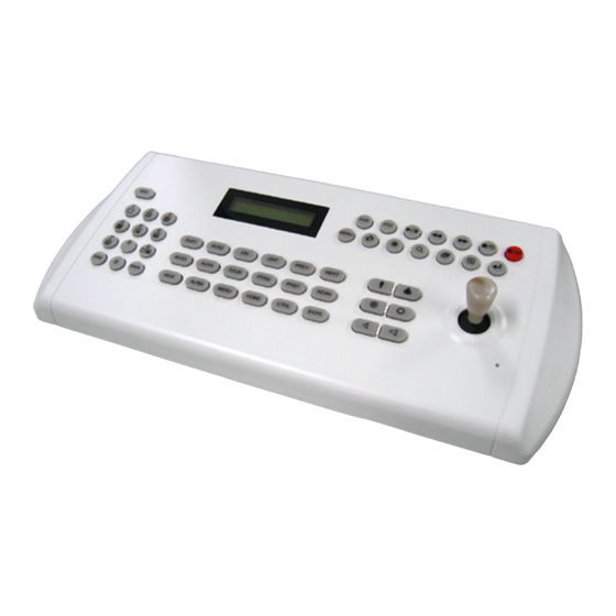
- Page 1 FASTRAX ll KEYBOARD CONTROLLER HID2404CZ & HID2404CL Instruction Manual HID2404CL HID2404CZ Please read this manual thoroughly before use and keep it handy for future reference. Rev.040922fa...
- Page 2 WARNING AND CAUTION WARNING TO REDUCE THE RISK OF FIRE OR ELECTRIC SHOCK, DO NOT EXPOSE THIS PRODUCT TO RAIN OR MOISTURE. DO NOT INSERT ANY METALLIC OBJECTS THROUGH THE VENTILATION GRILLS OR OTHER OPENINGS ON THE EQUIPMENT. CAUTION EXPLANATION OF GRAPHICAL SYMBOLS The lightning flash with arrowhead symbol, within an equilateral triangle, is intended to alert the user to the presence of uninsulated "dangerous voltage"...
- Page 3 FCC COMPLIANCE STATEMENT FCC INFORMATION: THIS EQUIPMENT HAS BEEN TESTED AND FOUND TO COMPLY WITH THE LIMITS FOR A CLASS A DIGITAL DEVICE, PURSUANT TO PART 15 OF THE FCC RULES. THESE LIMITS ARE DESIGNED TO PROVIDE REASONABLE PROTECTION AGAINST HARMFUL INTERFERENCE WHEN THE EQUIPMENT IS OPERATED IN A COMMERCIAL ENVIRONMENT.
- Page 4 IMPORTANT SAFEGUARDS 1. Read these instructions. 2. Keep these instructions. 3. Heed all warnings. 4. Follow all instructions. 5. Do not use this apparatus near water. 6. Clean only with dry cloth. 7. Do not block any ventilation openings. Install in accordance with the manufacturer's instructions.
-
Page 5: Table Of Contents
Table of Contents Chapter 1.0 INTRODUCTION 1.1 Features 1.2 Package Contents Chapter 2.0 INSTALLATION 2.1 Connection Diagram 2.1.1 Basic Installation Diagram 2.1.2 Single Multiplexer 2.1.3 Single User with Two Multiplexers 2.1.4 Two Multiplexers with Slave Keyboard Controller (method 1) 2.1.5 Two Multiplexers with Slave Keyboard Controller (method 2) 2.2 Termination &... -
Page 6: Features
Chapter 1 INTRODUCITON 1.1 Features This keyboard controller is capable of controlling 254 Fastrax II (E) dome cameras including 64 alarm function and remote control functions for a variety of external switching devices (e.g. Multiplexer(max 255), Digital Video Recorder(max 99) etc…) The keyboard controller features: •... - Page 7 Figure 1 – Typical system Configuration...
-
Page 8: Package Contents
1.2 Package Contents Unpack the equipment and make sure all listed items are included in the box. The package contains the following. Description Q’ty Keyboard controller Junction box (J-box) 3m 8pin cable (Unshielded cable) M4 x L10 Self tapping screws Instruction manual 12VDC Power supply (SMPS) Power Cord... -
Page 9: Chapter 2.0 Installation
Chapter 2 INSTALLATION 2.1 Connection Diagram 2.1.1 Basic Installation Diagram J-BOX DOME POWER RS485(+) DOME1 + RX+(TX+) AC 24V RS485(-) DOME1 - RX-(TX-) STP AWG # 22 ALARM OUTPUT ALARM INPUT POWER AC 24V SENSOR ALARM INPUT UP TO 8 FGND (RX+) (RX+) -
Page 10: Single Multiplexer
2.1.2 Single Multiplexer POWER POWER POWER AC 24V AC 24V AC 24V AWG # 24 (RS-422) SPOT MONITOR MAIN MONITOR MULTIPLEXER RS-485(+) PIN No.4 RS-485(-) PIN No.5 Figure 3 – Single Multiplexer... -
Page 11: Single User With Two Multiplexers
2.1.3 Single User with Two Multiplexers POWER POWER POWER AC 24V AC 24V AC 24V AWG # 24 (RS-422) 1ST MAIN MONITOR SPOT MONITOR 2ND MAIN MONITOR 1ST MULTIPLEXER 2ND MULTIPLEXER RS-485(+) PIN No.4 RS-485(-) PIN No.5 Spot output 1 of the first multiplexer to be connected to 16 input of the second multiplexer. -
Page 12: Two Multiplexers With Slave Keyboard Controller (Method 1)
2.1.4 Two Multiplexers with Slave Keyboard Controller (method 1) POWER POWER POWER AC 24V AC 24V AC 24V AWG # 24 (RS-422) SPOT MONITOR SPOT MONITOR 1ST MAIN MONITOR FOR SLAVE K/B FOR MASTER K/B 1ST MULTIPLEXER 2ND MULTIPLEXER RS-485(+) PIN No.4 RS-485(-) PIN No.5 Figure 5a –... -
Page 13: Two Multiplexers With Slave Keyboard Controller (Method 2)
2.1.5 Two Multiplexers with Slave Keyboard Controller (method 2) POWER POWER POWER AC 24V AC 24V AC 24V AWG # 24 (RS-422) SPOT MONITOR SPOT MONITOR 1ST MAIN MONITOR FOR SLAVE K/B FOR MASTER K/B 2ND MAIN MONITOR 1ST MULTIPLEXER 2ND MULTIPLEXER RS-485(+) PIN No.4 RS-485(-) PIN No.5... -
Page 14: Termination & Dip Switch Settings
2.2 Termination & Dip Switch Settings The first and last devices in an installation (dome and keyboard controller) must have the data line terminated by setting the DIP switch. Without proper termination, there is potential for control signal errors. Total length of the cable for communication should not exceed 1 mile. Refer to Figure 7 for setting the dome camera and keyboard controller termination. -
Page 15: Multiplexer Configuration
SETTING DISCRIPTION DOME1 Termination Mux/Slave Termination DOME2 Termination Reserved Slave Master Reserved Table 1 - S1 Switch Setting 2.3 Multiplexer Configuration Duplex setup: NOTE: Multiplexers to be controlled by the keyboard controller require a new ROM version. The new multiplexer ROM accepts control instructions from the keyboard controller. If your multiplexer’s serial number is M104xxxx or higher, then it is ready to accept control instructions. -
Page 16: Keyboard Setup
2.4 Keyboard Setup To setup the keyboard controllers, the user needs to setup the network, passwords and perform special tasks such as Uploading and Downloading programmed data from the dome cameras. To enter the Keyboard menu, press Ctrl + Menu. You will see the following menu. Joystick Up/Down scrolls menu items, push the stick to Right to enter the sub-menu. -
Page 17: Master/Slave Mode Setup
Save and Exit Note) AUX IN : auxiliary signal input (simplex mode) AUX I/O : when auxiliary signal input , respond to the signal (Half duplex mode) - Set Slave Kbd Slave Kbd : ON/OFF ON- Slave KBD exists, OFF- Not exist. MUX control : ON/OFF Set accessibility of the multiplexer menu at slave keyboard DVR control : ON/OFF... - Page 18 FASTRAX-2L Vxxx Slave ID = 1 Current Device ID = 1 Input Password : xxxx Default setting is 9999 for administrator, 1111 for user CAM:000 000 means that the controller is not connected to the master keyboard 3. Press CTRL + MENU. Set the Slave ID to 01 4.
- Page 19 4. How to setup the KBD controller. A. Switch the KBD controller ON B. Input password (Factory setting is 9 9 9 9 ) C. Open the menu of the KBD controller by pressing CTRL + MENU Key. D. Set as below in Network menu. Set Baud Rate Com Ports 9600...
- Page 20 F. Select “Camera” on the Device menu. Unit ID should be 1 up to 99. Unit ID is not allowed number “0”. G. Set “PTZ Device” and “ID” of the dome camera. Select RS232/RS485 after PTZ is installed, and then set-up as below table.
-
Page 21: Installing With Pc Dvr Series
RS232/RS485 Baud Rate Parity Data Stop Usage RS232 9600 None Remote Control RS485 9600 None PTZ Control 6. After setting Unit ID, Camera, and RS232/RS485, installing dome camera is basically completed. Please refer to the manual of DVR for the other installation. 7. - Page 22 C. Open the menu of the KBD controller by pressing CTRL + MENU Key. D. Set as below in Network menu. Set Baud Rate Com Ports 9600 Dome D2/DVR 9600 D2/DVR AUX IN MUX/AUX 9600 MUX/AUX None (OR ETC) DVR/AUX 9600 DVR/AUX PC-DVR...
- Page 23 Port : COM2 RX Device : Fastrax…. Baud Rate : 9600 Data Parity : None Stop Bit : XX D. If PTZ is not necessary for PC DVR, cable and installation here is not needed. (PC DVR is able to be controlled remotely and there’s no PTZ function) 6.
-
Page 24: Chapter 3.0 Operation
Chapter 3 OPERATION 3.1 Keyboard Lock/Unlock (Hidden command) When the user leaves the control desk, he may wish to lock the keyboard controller to prevent unauthorized use. Pressing 7 7 7 + ENTR will lock the keyboard controller. Pressing 7 7 7 + ENTR while the keyboard is locked will open the password screen. - Page 25 Select cameras 1 to 16 by pressing the camera number and then Main. The selected camera will appear in the full screen mode and is under control if it is a dome camera. Even if no camera is connected to the multiplexer input, the screen will show the camera input (see following example).
-
Page 26: Summary Of Keyboard Control
3 1 + CAM = camera 15 of the second multiplexer. 3.3 Summary of Keyboard Controls t|s{pwslly k}yGjvu{yvs jˆ”aWWXl vvtG~pkl vvtG{lsl pypzGjsvzl pypzGvwlu wjGk}yGjvu{yvs t|s{pwslly mvj|zGulhy mvj|zGmhy Figure 12 – Keyboard Key map Figure 13 – J-box Front & Rear Key operation example CTRL + MENU : Press and hold down CTRL Key and press MENU Key... -
Page 27: Keys For Dome Camera
3.3.1 Keys for Dome camera Function Key Label Descriptions Displays the selected camera on the spot out of the multiplexer and allows the camera to be controlled by the keyboard controller, if the selected camera is a dome Camera 0..9 + CAM camera. -
Page 28: Keys For Multiplexer
3.3.2 Keys for Multiplexer Function Key Label Descriptions No. + MAIN Full Screen Puts the multiplexer in Full-Screen Mode of the selected camera No. Picture-in-Picture mode. Displays view of four cameras. The remaining cameras can be sequenced in the 2 by 2 Display lower-right window. - Page 29 Stop/ During Playback mode returns the DVR to the Live Monitoring mode. In Preset Save case PTZ mode, Save current position to the preset No. Record/ Set the DVR so that it is ready to record video. In case PTZ mode, Recall Preset Call the preset No.
-
Page 30: Appendix A Trouble Shooting
Appendix A Trouble Shooting If problems occur, verify the installation of the camera with the instructions in this manual and with other operating equipment. Isolate the problem to the specific piece of equipment in the system and refer to the equipment manual for further information. -
Page 31: Appendix B Specification
Appendix B SPECIFICATION GENERAL Certification CE EMC, FCC CLASS A ELECTRICAL 16 X 2 Line LCD Joystick Zoom hand Joystick Input Voltage 12 VDC, built-in power-line surge Power Consumption Communications RS-485/232 baud rate: 2400 ~230k bps (default:9600bps) Dome1 Port (RS-485) Up to 127 dome cameras including 32 Alarm mode on Dome2 Port (RS-485) Up to 127 dome cameras including 32 Alarm mode on... - Page 32 KEYBOARD CONTROLLER FASTRAX ll 50301815B...