
Related Manuals for ION TITAN 2


Summary of Contents for ION TITAN 2
- Page 1 TITAN 2 Instrument User Manual V1.0 Pioneering Gas Sensing Technology. ionscience.com...
- Page 2 TITAN 2 Instrument User Manual V1.0 THIS PAGE IS LEFT INTENTIONALLY BLANK eering Gas Sensing Technology. Page 2 of 66 ionscience.com...
- Page 3 Thank you for purchasing your ION Science instrument. Register your instrument online for extended warranty The standard warranty of your Titan 2 Benzene Monitor can be extended up to two years. To receive your extended warranty, you must register your instrument online within one month of purchase (terms and conditions apply).
-
Page 4: Table Of Contents
Introduction to TITAN 2 ........................ 10 Technical Specification ......................... 11 Un-Packing ........................... 12 Titan 2 Benzene Monitor and Accessories Kit ................12 Titan 2 Detector Module and Accessories Kit ................. 13 System Description ........................14 The Gas Detector ........................... 14 Pneumatic Connections ......................... - Page 5 Alarm Indications ..........................45 Service Period Reminder........................45 Titan PC Software ......................... 46 Minimum requirements ........................46 Connect the Titan 2 to the PC ........................ 46 Starting the Software ..........................47 Data Connection............................ 48 Settings ..............................49 Data Download ............................. 50 Data View .............................
- Page 6 TITAN 2 Instrument User Manual V1.0 Upgrade ..............................54 Calibration ............................55 Recorded Faults ............................ 56 Alarm Set .............................. 58 Virtual Screen ............................58 Engineering ............................59 Bump Test ............................ 60 Use of the Test ............................60 Test Procedure ............................61 Fault Diagnostics ..........................
-
Page 7: Eu Declaration Of Conformity
TITAN 2 Instrument User Manual V1.0 EU Declaration of conformity eering Gas Sensing Technology. Page 7 of 66 ionscience.com... -
Page 8: Statements
"as is" and without any representation, term, condition or warranty of any kind, either expressed or implied. To the extent permitted by law, Ion Science shall not be liable to any person or entity for any loss or damage which may arise from the use of this manual. -
Page 9: Service
A-875417 : Hydrophobic Filter A-875505 : Carbon Filter Assembly (with Connectors) A-924217 : Inline Filter assembly A-924218 VRV restrictor assembly Contact ION Science or your local distributor for service options in your area. eering Gas Sensing Technology. Page 9 of 66 ionscience.com... -
Page 10: Introduction To Titan 2
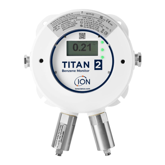
TITAN 2 Instrument User Manual V1.0 Introduction to TITAN 2 The TITAN 2 is a fixed benzene monitor certified for Zone 1 hazardous areas. It detects 0.02 - 20 ppm concentrations in ambient air, taking one sample per minute. It monitors both the current benzene concentration and the STEL (Short-Term Exposure Limit, calculated over the previous 15 minutes). -
Page 11: Technical Specification
TITAN 2 Instrument User Manual V1.0 Technical Specification MiniPID T2 10.0 eV Sensor Sensor type: Benzene specific within typical petrochemical matrix Selectivity: 0.02 ppm - 20 ppm Detectable range: One minute Measurement frequency: 0.02 ppm (20 ppb) (10 ppb resolution) Lower limit of detection: ±... -
Page 12: Un-Packing
Remove the contents carefully and check them against the packing list. Report discrepancies between the contents and the packing list to Ion Science Ltd. Ion Science will not be responsible for discrepancies not reported within ten days of your receipt of the shipment. -
Page 13: Titan 2 Detector Module And Accessories Kit
A-875505 Carbon Filter Assembly – Certificate of Calibration Titan 2 Label Information: Ensure Warning Label is attached to Titan 2. WARNING: DO NOT OPEN WHILE ENERGIZED! WARNING: DO NOT OPEN WHILE A HAZARDOUS ATMOSPHERE MAY BE PRESENT! Refer to instruction manual/booklet... -
Page 14: System Description
To make the measurements specific to benzene, it must be separated out from the other gasses before the PID measurement. Titan 2 incorporates the MiniPID T2, this sensor is humidity resistant and has an anti contamination design. -
Page 15: Pneumatics
The external (hydrophobic) filter removes particles and moisture from the inlet Flow. Every three hours by the clock (00:00, 03:00, 06:00…) the Titan 2 will stop to measure the ambient pressure conditions to correctly adjust for flow control. Important note: bump testing is inadvisable at these times as external pressure sources will affect the pressure... -
Page 16: Heaters
TITAN 2 Instrument User Manual V1.0 Heaters The Titan 2 has two heating systems, one regulates the internal temperature, the other regulates the temperature of the AirSep filter. Internal temperature regulation is maintained by a set of four resistors in the base of the Housing Module. -
Page 17: Outputs And Communications
Both relays can be programed to be Normally Open or Normally Closed. They can switch 24VDC at 1.5A maximum load. When the Titan 2 is not powered the default state of relay 1 is N/C, the default state of relay 2 is N/O Data is stored internally for a minimum of two years and can be downloaded with Titan 2PC software via USB or RS485 for analysis and archive storage. -
Page 18: Rs485 Modbus Interface
TITAN 2 Instrument User Manual V1.0 RS485 Modbus Interface The Titan 2 Modbus interface uses either Serial ASCII format Modbus or RTU, at: • 38400 baud 8 data bits, no parity, 2 stop bits. Function Codes Titan 2 supports these function codes: 0x03 –... - Page 19 Heater drive power in % x 100 Heater driver voltage Power supply level x 10 Heater level Unique ID of Titan 2 – a string of 16 ASCII characters 1000 unique to each Titan 2 1100 Firmware versions of Titan 2 and Flow Controller. Two null terminated strings are returned.
-
Page 20: Holding Registers Address Map
Total available clusters Reserved clusters. 1400 Returns an array of 27 32-bit integers indicating internal fault state of Titan 2. If there are no faults all values are zero. 1500 Returns five 32-bit integers indicating state of the lamp sensor. - Page 21 Day of year 1300 Used during code upgrade. For ISL use only. Reading or Writing to this address may require you to send the Titan 2 to a Service Center. 1400 Used during upgrade of flow controller. For ISL use only.
-
Page 22: System Files
• vertically, with the flame arresters underneath the housing • not in direct sunlight or over a heat source (This can cause the Titan 2 to exceed its certified internal working temperature of 50degC) • not in areas likely to flood. -
Page 23: Power Requirements
TITAN 2 Instrument User Manual V1.0 NOTE: Whether the gas inputs to the unit are from the area where the flame proof box is installed or whether it inputs from another source. The gas which is pumped inside the flame proof box must be from the area where the flame proof box is installed. -
Page 24: Rs485 Connections
TITAN 2 Instrument User Manual V1.0 RS485 Connections You can use Titan 2 for half-duplex, 2-wire communication. You can also configure it to use a built-in 120R termination resistor. Pin references are to Terminal Block-2 (Refer to Installation, Terminal Block-2) A (Pin5) -
Page 25: Dimensions For Installation
All dimensions in mm. To Install the Housing Module Use M10 screws to install the Titan 2 as a complete unit (housing and detection modules together) on a solid, stable support. After you install the Titan 2, remove the detection module to get access to the terminal blocks. Refer to remoal and installion of the detection module. -
Page 26: After-Installation Test
Do a "Bump Test" to verify that the sensors respond correctly to the Benzene gas. Refer to Bump test. For an accurate bump test the Titan 2 needs to heat up and thermally stabilise. This can take up to 90 minutes. Before this an inaccuracy of up to 15% could be seen. -
Page 27: Terminal Block-2 (Communications)
TITAN 2 Instrument User Manual V1.0 The 4-20mA output can share the instrument Power Supply if: • the 4-20mA output goes to the same location as the instrument power supply and • their Grounds will be connected together. If that is so, connect a jumper from Pin 9 of Terminal Block-1 to Pin-1 of... -
Page 28: Circuit Diagrams For 4-20 Ma Monitoring
TITAN 2 Instrument User Manual V1.0 Circuit diagrams for 4-20 mA monitoring On-board-Fuse (375mA / F2) Ammeter for current +24V measurement 4-20mA Power Supply On-board-Fuse (375mA / F2) Current Sense Measurement Resistor +24V 4-20mA Circuitry Power Supply eering Gas Sensing Technology. -
Page 29: Removal And Installation Of The Detection Module
TITAN 2 Instrument User Manual V1.0 Removal and Installation of the Detection Module To Remove the Detection Module Switch off or remove the power to the Titan 2. WARNING: 1. Ensure the electrical power is switched off or disconnected. 2. Do not open when an explosive atmosphere might be present. - Page 30 TITAN 2 Instrument User Manual V1.0 Two captive, hex-socket screws hold the Detection Module in the Housing Module, as shown. Two holes in the front of the Detection Module give access to the screws. Use a 3mm allen-key to reach the screws directly behind the holes.
-
Page 31: To Install The Detection Module
TITAN 2 Instrument User Manual V1.0 Ensure the pneumatic tubes are properly identified for later connection to the correct connectors. Disconnect the tubes only from the Detection Module, not from the Housing Module. The tubes must remain connected at all times to the barbs on the interior face of the flame- arrestors. - Page 32 TITAN 2 Instrument User Manual V1.0 Use the allen-key to engage the captive screw at each side of the Detection Module. If the module is in its correct position, the screws will engage in the threads and turn freely. If they do not engage the threads easily, check the positon of the Detection Module.
- Page 33 The date and time is used to "Date-stamp" all data files and calibration history. Without external power, Titan 2 can only store the current date and time for a maximum of 12 hours. Install the front cover. Turn it clock-wise until it is hand-tight.
- Page 34 TITAN 2 Instrument User Manual V1.0 Ensure the external hydrophobic filter and any exhaust or inlet probe lines are connected. Switch on or connect the power supply. Do an after-installation test. Refer to After-Installation Test. eering Gas Sensing Technology. Page 34 of 66...
-
Page 35: Operating The Titan 2
(ppm). This updates once per minute. Main screens and main menu The actuation magnet supplied with the Titan 2 operates the magnetic switches through the front cover. On the main operation screen: • Select Switch 2 to toggle between the current reading and the calculated STEL (Short-Term Exposure Limit) over the previous 15 minutes. -
Page 36: Menu Icons
Relay Relay 1 Relay 2 Navigation The actuation magnet supplied with the Titan 2 operates the magnetic switches through the front cover. • Use Switch 1 to move to the next icon or value (options). • Use Switch 2 to select an option or toggle between values. -
Page 37: Benzene Calibration
Move the cursor to the ppm value. Use Switch 2 to cycle through the values to the benzene concentration of the bottle. Move the cursor to the Cycles value. This allows you to change the number of 1-minute cycles the Titan 2 will do during calibration. -
Page 38: Removal Of The Memory Card
Do a Bump Test to check the calibration. Refer to Bump Test. Removal of the Memory Card You can remove the memory card from the Titan 2. You can then connect the card to a PC and use Titan PC software to download and read the data. -
Page 39: Password Lock
Prevent viewing of measured benzene levels: so the STEL and LIVE benzene displays will be blank. You will use a 4-digit pin to turn the lock function on or off. Titan 2 is supplied with a default PIN of 0000 and with calibration and viewing unlocked. Select the lock icon on the main menu. - Page 40 TITAN 2 Instrument User Manual V1.0 On the "Enter new PIN" screen, use Switch 2 to cycle through the values to set the first digit. Use Switch 1 to move to the next digit. When all the digits are set: •...
-
Page 41: Lock The Stel And Live Displays
The alarms and relays are individually programmable to the settings required by the site policy. You can choose either alarm to energize either relay. The default settings would be. When the Titan 2 is not powered the default state of relay 1 is N/C, the default state of relay 2 is N/O. -
Page 42: Alarm Or Relay Selection
TITAN 2 Instrument User Manual V1.0 Alarm or Relay Selection Select: • Alarm 1 • Alarm 2 • Relays That takes you to the configuration screen for that item. Alarm Configuration The configuration procedure for Alarm 1 is shown. Alarm 2 is the same. -
Page 43: Relays And 4-20Ma Test
TITAN 2 Instrument User Manual V1.0 Relays and 4-20mA Test Do a test of the relay and the 4-20mA systems to check for correct installation and function. Select Relay 1, Relay 2 or 4-20mA. That takes you to the test screen for the relay or 4-20mA system. -
Page 44: Fault Indications
TITAN 2 Instrument User Manual V1.0 Information Page 4 Titan 2 internal temperature AirSep temperature Information Page 5 Firmware version number Pump Driver Board Version Number Information Page 6 Instrument serial number User settable location Processor serial number Information Page 7... -
Page 45: Alarm Indications
TITAN 2 Instrument User Manual V1.0 Alarm Indications If the benzene level exceeds one of the two target concentration values selected during Alarm Configuration: • The three LEDs on the front panel show red. • An alarm symbol and the alarm number, is displayed in the top right of the screen. -
Page 46: Titan Pc Software
Windows 10 • Windows 11 Connect the Titan 2 to the PC 1. Install the Detector Module into the Test Housing Module. 2. Connect the USB or RS485 output to the PC. 3. Connect or switch on the power supply. -
Page 47: Starting The Software
TITAN 2 Instrument User Manual V1.0 Starting the Software After installation, click on the Titan PC icon on the desktop to start the software. Titan PC shows a start-up window while loading the software, then the Main Operation Window when ready for use. -
Page 48: Data Connection
After connection, you can download and view the data on the card. If Titan 2 is connected via USB, and the PC is connected to the internet, you can tick the check-box to allow Ion Service Support to remotely connect to the Titan 2 to view factory level data and configuration values. -
Page 49: Settings
NOTE: The Titan 2 internal clock is automatically set during calibration using Titan PC. Without external power, Titan 2 can only store the current date and time for a maximum of 12 hours. eering Gas Sensing Technology. -
Page 50: Data Download
TITAN 2 Instrument User Manual V1.0 Data Download Click on the icon for the Data Download window. When data is available to download, a list of the available dates is displayed under "File Date" on the left. If necessary, click "Refresh" to scan the instrument for fresh data. -
Page 51: Data View
Data Download window. Data View allows you to view, print or save pictures of graphs of the data in files downloaded from Titan 2 using Data Download. You can change the presentation to how you want to see it. - Page 52 TITAN 2 Instrument User Manual V1.0 Hold down the left mouse button to grab and drag the graph around the screen. Use the mouse wheel to zoom in and out. There are 5 control buttons at the top right of the screen: Scales –...
- Page 53 TITAN 2 Instrument User Manual V1.0 Print. Click this to print the view you have on the screen. Save as a Picture. Click this to save the view you have on the screen, as a picture. You can save in jpg, emf, bmp, tif, png, or gif format.
-
Page 54: Upgrade
TITAN 2 Instrument User Manual V1.0 Upgrade Click on the icon for the Upgrade window. If the PC is connected to the internet Titan PC will automatically detect if a new version of firmware or software is available. If new firmware or software is available, you can view the release notes or do an upgrade. -
Page 55: Calibration
Attach a bottle between 0.1 ppm – 20 ppm Benzene to the inlet flame-arrestor before you start calibration. This ensures the benzene is flowing through the Titan 2 system before the start of the calibration. Click the "Start Calibration" button. The text on the button will change to “Abort Calibration.” You can click the button again to any time to stop the calibration and reset the screen to its original state. -
Page 56: Recorded Faults
For more details of the fault conditions, refer to the Fault Diagnostics section of this manual. Pressing the ‘Read Diagnostic Log’ button opens the following screen. The diagnostic file and comments can be sent to Ion Science or to an e-mail of the user’s choice. - Page 57 TITAN 2 Instrument User Manual V1.0 eering Gas Sensing Technology. Page 57 of 66 ionscience.com...
-
Page 58: Alarm Set
Click on the icon for the Virtual Screen window. This tab displays in real time what is displayed on the Titan 2 screen. A radio button allows the user to switch between the current cycle reading and the calculated STEL. -
Page 59: Engineering
TITAN 2 Instrument User Manual V1.0 Engineering Click on the spanner icon to access the engineer section. In this section, you can access information on the instruments control, signal process and flow. Control Control includes the following information: ByPass Flow, Clock, Heater, Identity, Sampling, Temperature. -
Page 60: Bump Test
Flow includes information on the following: Outer loop pump, valve control, inner loop, outer loop and flow control. Bump Test A "Bump Test" is not a calibration. The test verifies that the Titan 2 is accurately measuring benzene at a known concentration supplied from a bottle. -
Page 61: Test Procedure
Connect the bottle to the hydrophobic filter on the inlet flame-arrestor. Allow 3 minutes for the reading on the Titan 2 display to stabilise. If the Titan 2 does not display the gas concentration given by the bottle, calibrate the Titan 2 to give the correct readings. Refer to:... -
Page 62: Fault Diagnostics
Fault Conditions The Titan 2 is equipped with a number of diagnostics to ensure instrument faults are detected and communicated. The table gives a fuller description of each fault and list some possible causes and corrective actions you can try. - Page 63 TITAN 2 Instrument User Manual V1.0 Sensor flow low: AirSep flow too low. Check for kinks or pinches in the tube between port 3 2.250 Yellow and the inlet flame- arrester. Sensor flow high: AirSep flow too high. Check that AirSep filter is pushed in firmly and 2.375...
- Page 64 TITAN 2 Instrument User Manual V1.0 No signal from PID Light PID Lamp not illuminated. sensor. Sensor failure. 2.875 Yellow During Titan 2 start-up, wait at least 5 cycles for the lamp to illuminate. Memory full: Not enough memory Memory full.
-
Page 65: Titan Pc Fault Groups
TITAN 2 Instrument User Manual V1.0 Titan PC Fault Groups To reduce file size and memory usage, fault records are grouped together in the files stored on the Titan 2 and downloaded to the Titan PC. Titan PC Group Name... -
Page 66: Ion Science Contact Details
TITAN 2 Instrument User Manual V1.0 ION Science Contact Details ION Science Ltd – UK/Head Office Tel: +44 (0)1763 208 503 Web: www.ionscience.com | Email: info@ionscience.com ISM ION Science Messtechnik – Germany Office Tel: +49 (0) 2104 1448-0 Web: https://www.ism-d.de/en/ | Email: sales@ism-d.de...