Table of Contents
Advertisement
Quick Links
ProtoNode FPC-N34 and ProtoNode FPC-N35
Startup Guide
For Interfacing Products: ENVI, LOVE, NURO
To Building Automation Systems:
BACnet MS/TP, BACnet/IP, Modbus TCP/IP, Metasys N2
and LonWorks
APPLICABILITY & EFFECTIVITY
Explains ProtoNode hardware and installation.
The instructions are effective for the above as of April 2016.
Document Revision: 14.B
Auto Discovery
Template Revision: 57
Advertisement
Table of Contents

Related Manuals for SMC Networks ProtoNode FPC-N34


Summary of Contents for SMC Networks ProtoNode FPC-N34
- Page 1 ProtoNode FPC-N34 and ProtoNode FPC-N35 Startup Guide For Interfacing Products: ENVI, LOVE, NURO To Building Automation Systems: BACnet MS/TP, BACnet/IP, Modbus TCP/IP, Metasys N2 and LonWorks APPLICABILITY & EFFECTIVITY Explains ProtoNode hardware and installation. The instructions are effective for the above as of April 2016.
- Page 2 ProtoNode Startup Guide Technical Support Thank you for purchasing the ProtoNode. Please call 570-476-7261, for Technical support of the ProtoNode product. SMC does not provide direct support. If concerns need to be addressed by SMC, they will contact Sierra Monitor Corporation for assistance. Technical Support Contact Information: Technical Service: 570-476-7261...
- Page 3 2.1) 2. Set the device’s Modbus RTU serial settings (i.e. baud rate, parity, stop bits) and Modbus Node-ID for each of the devices that will be connected to ProtoNode FPC-N34 or FPC-N35. (Section 2.3) 3. ProtoNode FPC-N34 units: Select the Field Protocol on the S Bank Dip Switches. (Section 2.4.1)
- Page 4 ProtoNode Startup Guide Certifications – BTL MARK BACNET TESTING LABORATORY The BTL Mark on ProtoNode is a symbol that indicates that a product has passed a series of rigorous tests conducted by an independent laboratory which verifies that the product correctly implements the BACnet features claimed in the listing.
-
Page 5: Table Of Contents
2.5.4 BACnet MS/TP (FPC-N34): Setting the Baud Rate for BMS Network ........14 Interfacing ProtoNode to Devices ..................... 15 ProtoNode FPC-N34 and FPC-N35 Showing Connection Ports ..........15 Device Connections to ProtoNode ....................16 Connecting NURO Modbus RTU Boilers to the ProtoNode’s RS-485......... 16 3.2.1... - Page 6 Figure 8: BMS Baud Rate DIP Switches ...................... Figure 9: BMS Baud Rate ..........................14 Figure 10: ProtoNode FPC-N34 (upper) and ProtoNode FPC-N35 (lower) ..........Figure 11: Wiring diagram for Modbus RTU RS-485 connections to the ProtoNode’s RS-485 port ....
-
Page 7: Introduction
ProtoNode Startup Guide 1 I N T R O D U C T I O N 1.1 ProtoNode Gateway ProtoNode is an external, high performance Building Automation multi-protocol gateway that is “device”) preconfigured to Auto-Discover the products (hereafter called connected to the ProtoNode and ®1 ®2 automatically configures them for BACnet... -
Page 8: Setup For Protonode
ProtoNode Startup Guide SETUP FOR PROTONODE 2.1 Record Identification Data Each ProtoNode has a unique part number located on the side or the back of the unit. This number should be recorded, as it may be required for technical support. The numbers are as follows: Model Part Number ProtoNode N34... -
Page 9: Configuring Device Communications
ProtoNode Startup Guide 2.3 Configuring Device Communications 2.3.1 Set COM setting on all of the Devices connected to the ProtoNode • Set up all devices on the same subnet as the ProtoNode. • All of the serial devices connected to ProtoNode MUST have the same Baud Rate, Data Bits, Stop Bits, and Parity settings. -
Page 10: Selecting The Desired Field Protocol And Enabling Auto-Discovery
2.4 Selecting the Desired Field Protocol and Enabling Auto -Discovery 2.4.1 Selecting Desired Field Protocol • ProtoNode FPC-N34 units use the “S” bank of DIP switches (S0 – S2) to select the Field Protocol. See the table in Figure 5 for the switch settings for the ProtoNode. -
Page 11: Enabling Auto-Discovery
ProtoNode Startup Guide 2.4.2 Enabling Auto-Discovery NOTE: If Modbus TCP/IP was selected in Section 2.4.1 for the Field/BMS protocol, skip this section. Auto-Discovery is NOT used for Modbus TCP/IP. The S3 DIP switch is used to both enable Auto-Discovery of known devices attached to the ProtoNode, and to save the recently discovered configuration. -
Page 12: Bms Network Settings: Mac Address, Device Instance And Baud Rate
ProtoNode Startup Guide 2.5 BMS Network Settings: MAC Address, Device Instance and Baud Rate 2.5.1 BACnet MS/TP (FPC-N34): Setting the MAC Address for BMS Network • Only 1 MAC address is set for ProtoNode regardless of how many devices are connected to ProtoNode. -
Page 13: Bacnet Ms/Tp And Bacnet/Ip (Fpc-N34): Setting The Device Instance
ProtoNode Startup Guide 2.5.2 BACnet MS/TP and BACnet/IP (FPC-N34): Setting the Device Instance • The BACnet Device Instances will be calculated by adding the Node_Offset (default value is 50,000) to the device’s Modbus Node ID (that was assigned in Section ). •... -
Page 14: Bacnet Ms/Tp (Fpc-N34): Setting The Baud Rate For Bms Network
• The baud rate on ProtoNode for Metasys N2 is set for 9600. “B” bank DIP switches B0 – B3 are disabled for Metasys N2 on ProtoNode FPC-N34. • “B” bank DIP switches B0 – B3 are disabled on ProtoNode FPC-N35 (LonWorks). -
Page 15: Interfacing Protonode To Devices
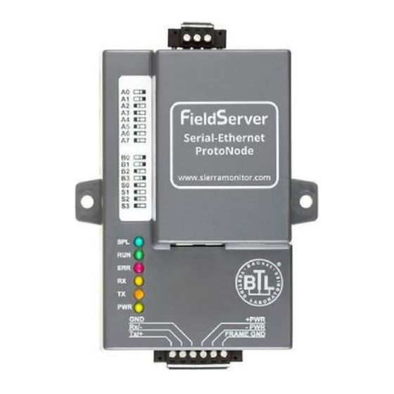
ProtoNode Startup Guide INTERFACING PROTONODE TO DEVICES 3.1 ProtoNode FPC-N34 and FPC-N35 Showing Connection Ports Figure 10: ProtoNode FPC-N34 (upper) and ProtoNode FPC-N35 (lower) Page 15 of 50... -
Page 16: Device Connections To Protonode
ProtoNode Startup Guide 3.2 Device Connections to ProtoNode ProtoNode 6 Pin Phoenix connector for RS-485 Devices • The 6 pin Phoenix connector is the same for ProtoNode FPC-N34 (BACnet) and FPC-N35 (LonWorks). • Pins 1 through 3 are for Modbus RS-485 devices. -
Page 17: Biasing The Modbus Rs-485 Device Network
ProtoNode Startup Guide 3.2.4 Biasing the Modbus RS-485 Device Network • An RS-485 network with more than one device needs to have biasing to ensure proper communication. The biasing only needs to be done on one device. • None of the ENVI’s support biasing. The ProtoNode is required to bias the RS-485 network. •... -
Page 18: End Of Line Termination Switch For The Modbus Rs-485 Device Network
ProtoNode Startup Guide 3.2.5 End of Line Termination Switch for the Modbus RS -485 Device Network • On long RS-485 cabling runs, the RS-485 trunk must be properly terminated at each end. • The ProtoNode has an End of Line (EOL) blue jumper. The default setting for this Blue EOL switch is OFF with the jumper straddling the pins closest to the inside of the board of the ProtoNode. -
Page 19: Bacnet Ms/Tp Or Metasys N2 (Fpc-N34): Wiring Field Port To Rs-485 Bms Network
3.3 BACnet MS/TP or Metasys N2 (FPC-N34): Wiring Field Port to RS-485 BMS Network • Connect the BACnet MS/TP or Metasys N2 RS-485 network wires to the 3-pin RS-485 connector on ProtoNode FPC-N34. (Figure The RS-485 GND (Pin 3) is not typically connected •... -
Page 20: Power-Up Protonode
ProtoNode Startup Guide 3.5 Power-Up ProtoNode Apply power to ProtoNode as show below in Figure 18. Ensure that the power supply used complies with the specifications provided in Appendix D.1. • ProtoNode accepts either 9-30VDC or 12-24 VAC on pins 4 and 5. •... -
Page 21: Auto-Discovery: After Completion - Turn Off To Save Configuration
ProtoNode Startup Guide – 3.5.1 Auto-Discovery: After Completion Turn Off to Save Configuration NOTE: If Modbus TCP/IP was selected in Section 2.4.1 for the Field/BMS protocol, skip this section. Auto-Discovery is NOT used for Modbus TCP/IP. The S3 DIP Switch for Enabling Auto-Discovery should have been set in Section 2.4.2 before applying power to the ProtoNode. -
Page 22: Bacnet/Ip Or Modbus Tcp/Ip: Change The Protonode Ip Address
ProtoNode Startup Guide BACNET/IP OR MODBUS TCP/IP: CHANGE THE PROTONODE IP ADDRESS 4.1 Connect the PC to ProtoNode via the Ethernet Port • Connect a CAT5 Ethernet cable (Straight through or Cross-Over) between the local PC and ProtoNode. • The Default IP Address of ProtoNode is 192.168.1.24, Subnet Mask is 255.255.255.0. If the PC and ProtoNode are on different IP Networks, assign a static IP Address to the PC on the 192.168.1.xxx network. -
Page 23: Bacnet/Ip And Modbus Tcp/Ip: Setting Ip Address For Field Network
ProtoNode Startup Guide 4.2 BACnet/IP and Modbus TCP/IP: Setting IP Address for Field Network • After setting a local PC on the same subnet as the ProtoNode (Section 4.1), open a web browser on the PC and enter the IP Address of the ProtoNode; the default address is 192.168.1.24. •... -
Page 24: Figure 21: Changing Ip Address Via Web Gui
ProtoNode Startup Guide • From the Web GUI’s landing page, click on “Setup” to expand the navigation tree. Then select “Network Settings” to access the IP Settings menu. (Figure Figure 21: Changing IP Address via Web GUI • Modify the IP Address (N1 IP Address field) of the ProtoNode Ethernet port. •... -
Page 25: Bacnet Ms/Tp And Bacnet/Ip: Setting Node_Offset To Assign Specific Device Instances
ProtoNode Startup Guide 5 BACNET MS/TP AND BACNET/IP: SETTING NODE_OFFSET TO ASSIGN SPECIFIC DEVICE INSTANCES • After setting a local PC to the same subnet as the ProtoNode (Section 4.1), open a web browser on the PC and enter the IP Address of the ProtoNode; the default address is 192.168.1.24. •... -
Page 26: How To Start The Installation Over: Clearing Profiles
ProtoNode Startup Guide 6 HOW TO START THE INSTALLATION OVER: CLEARING PROFILES • After setting a local PC to the same subnet as the ProtoNode (Section 4.1), open a web browser on the PC and enter the IP Address of the ProtoNode; the default address is 192.168.1.24. •... -
Page 27: Lonworks (Fpc-N35): Commissioning Protonode On A Lonworks Network
ProtoNode Startup Guide LONWORKS (FPC-N35): COMMISSIONING PROTONODE ON A LONWORKS NETWORK Commissioning may only be performed by the LonWorks administrator. 7.1 Commissioning ProtoNode FPC-N35 on a LonWorks Network The User will be prompted by the LonWorks Administrator to hit the Service Pin on the ProtoNode FPC-N35 at the correct step of the Commissioning process which is different for each LonWorks Network Management Tool. -
Page 28: Figure 24: Sample Of Fserver.xif File Generated
ProtoNode Startup Guide • For Windows XP and Windows 7, select: Use the following IP Address. • Click twice. • Open a web browser and go to the following address: [IP Address of ProtoNode]/fserver.xif. o Example: 192.168.1.24/fserver.xif • If the web browser prompts to save the file, save the file onto the local PC. If the web browser “... -
Page 29: Cas Bacnet Explorer For Validating Protonode In The Field
ProtoNode Startup Guide CAS BACNET EXPLORER FOR VALIDATING PROTONODE IN THE FIELD Sierra Monitor has arranged a complementary 2 week fully functional copy of CAS BACnet Explorer (through Chipkin Automation) that can be used to validate BACnet MS/TP and/or BACnet/IP communications of ProtoNode in the field without having to have the BMS Integrator on site. -
Page 30: Cas Bacnet Setup
8.2.1 CAS BACnet MS/TP Setup • Using the serial or USB to RS-485 converter, connect it to the local PC and the 3 Pin BACnet MS/TP connector on ProtoNode FPC-N34. • In CAS Explorer, do the following: Click on settings... -
Page 31: Appendix A. Troubleshooting
ProtoNode Startup Guide Appendix A. Troubleshooting Appendix A.1. Lost or Incorrect IP Address • Ens ure that F iel dServ e r Toolbox is l oade d on to the loc al PC. If n ot, downl oad Field Serv er - Toolbox .z i p on th e S ierra Mon ito r webpage , und er Cus tomer Care - Res ourc e Center, S oft ware Down loads : htt p:/ /www.s ierramon itor.c o m/c us tomer - c are/res ourc e - c enter?filters = s oftware - downl o ads... -
Page 32: Appendix A.2. Viewing Diagnostic Information
ProtoNode Startup Guide Appendix A.2. Viewing Diagnostic information • Type the IP Address of the ProtoNode into the web browser or use the FieldServer Toolbox to connect to the ProtoNode. • Click on Diagnostics and Debugging Button, then click on view, and then on connections. •... -
Page 33: Appendix A.3. Check Wiring And Settings
ProtoNode Startup Guide Appendix A.3. Check Wiring and Settings • No COMS on Modbus RTU side. If Tx/Rx are not flashing rapidly then there is a COM issue on the Modbus side. To fix this problem, check the following: Visual observations of LEDs on ProtoNode (Appendix A.7) Check baud rate, parity, data bits, stop bits Check Modbus device address... - Page 34 ProtoNode Startup Guide Step 1: Take a Log Click on the diagnose icon of the desired device Select full Diagnostic Page 34 of 50...
- Page 35 ProtoNode Startup Guide NOTE: If desired, the default capture period can be changed. Click on “Start Diagnostic” Wait for Capture period to finish, then the Diagnostic Test Complete window will appear Step 2: Send Log Once the Diagnostic test is complete, a .zip file will be saved on the PC Choose open to launch explorer and have it point directly at the correct folder Send the Diagnostic zip file to PKCHTsupport@spx.com...
-
Page 36: Appendix A.5. Update Firmware
ProtoNode Startup Guide Appendix A.5. Update Firmware To load a new version of the firmware, follow these instructions: 1. Extract and save the new file onto the local PC. 2. Open a web browser and type the IP Address of the FieldServer in the address bar. NOTE: Default IP Address is 192.168.1.24 NOTE: Use the FS Toolbox utility if you do not know the IP Address (Appendix A.1) -
Page 37: Appendix A.7. Led Diagnostics For Communications Between Protonode And Devices
ProtoNode Startup Guide Appendix A.7. LED Diagnostics for Communications Between ProtoNode and Devices Please see the diagram below for ProtoNode FPC-N34 and FPC-N35 LED Locations. Diagnostic LEDs Description The SPL LED will light if the unit is not getting a response from one or more of the configured devices. -
Page 38: Appendix B. Vendor Information
ProtoNode Startup Guide Appendix B. Vendor Information NOTE: All Modbus TCP/IP registers are the same as the Modbus RTU registers for the serial device. If this point list is needed, contact the OEM. The Modbus TCP/IP node address of the device is also the same as the Modbus RTU node address. Appendix B.1. - Page 39 ProtoNode Startup Guide Water Level nvoWaterLvl_XXX SNVT_switch DA_Bit_XXX Low Gas Pressure nvoLoGasPrs_XXX SNVT_switch DA_Bit_XXX Air Pressure nvoAirPrs_XXX SNVT_switch DA_Bit_XXX Blocked Flue nvoBlckdFlue_XXX SNVT_switch DA_Bit_XXX CH Pump nvoCHPump_XXX SNVT_switch DA_Bit_XXX DHW Pump nvoDHWPump_XXX SNVT_switch DA_Bit_XXX Air Damper nvoAirDamper_XXX SNVT_switch DA_Bit_XXX High Gas Pressure nvoHiGasPrs_XXX SNVT_switch DA_Bit_XXX...
- Page 40 ProtoNode Startup Guide 4) “Error Code” Codes: 1=ignition failure; 4=max ΔT exceeded; 5=internal error gas valve relay; 6=internal error safety relay; 7=rapid rise outlet temperature; 8=fan wrong speed; 10=internal error E2PROM signal; 11=UV sensor defect; 12=internal error E2PROM error; 15=rapid rise inlet temperature;...
-
Page 41: Appendix B.1. Envi Modbus Rtu Mappings To Bacnet, Metasys N2, Modbus Tcp/Ip And Lonworks38 Appendix B.2. Love Modbus Rtu Mappings To Bacnet, Metasys N2, Modbus Tcp/Ip And Lonworks
ProtoNode Startup Guide Appendix B.2. LOVE Modbus RTU Mappings to BACnet, Metasys N2, Modbus TCP/IP and LonWorks BACnet BACnet Data Array Object Object Data Point Point Name Lon Name Lon SNVT Offset Name Type Type Address Process Value nvoProcVal_XXX SNVT_count_inc_f DA_U16_XXX Setpoint nvi/nvoSetpoint_XXX... - Page 42 ProtoNode Startup Guide PV Value for Error 0002H nvoPVValEr2H_XXX SNVT_count_inc_f DA_U16_XXX Input Sensor Did Not Connect nvoInSnNoCnc_XXX SNVT_count_inc_f DA_U16_XXX PV Value for error 0003H nvoPVValEr3H_XXX SNVT_count_inc_f DA_U16_XXX Input Signal Error nvoInSigErr_XXX SNVT_count_inc_f DA_U16_XXX PV Value for Error 0004H nvoPVValEr4H_XXX SNVT_count_inc_f DA_U16_XXX Over Input Range nvoOvrInRng_XXX...
-
Page 43: Appendix B.3. Nuro Modbus Rtu Mappings To Bacnet, Metasys N2, Modbus Tcp/Ip And Lonworks
ProtoNode Startup Guide Appendix B.3. NURO Modbus RTU Mappings to BACnet, Metasys N2, Modbus TCP/IP and LonWorks BACnet BACnet Data Array Object Object Data Point Point Name Lon Name Lon SNVT Offset Name Type Type Address Supply Temperature nvoSupplyTmp_XXX SNVT_temp_p DA_Scl_XXX Return Temperature nvoReturnTmp_XXX... - Page 44 ProtoNode Startup Guide Relay A nvoRelayA_XXX SNVT_switch DA_Bit_XXX Relay B nvoRelayB_XXX SNVT_switch DA_Bit_XXX Relay C nvoRelayC_XXX SNVT_switch DA_Bit_XXX Relay D nvoRelayD_XXX SNVT_switch DA_Bit_XXX External Ignition nvoExtIgn_XXX SNVT_switch DA_Bit_XXX Gas Valve nvoGasValve_XXX SNVT_switch DA_Bit_XXX Alarm Relay nvoAlmRelay_XXX SNVT_switch DA_Bit_XXX Interlock Control Circuit nvoIntCtlCkt_XXX SNVT_switch DA_Bit_XXX...
- Page 45 ProtoNode Startup Guide NOTES: 1) Normal temperatures are °F with 1 decimal of precision. The values listed below indicate there is a problem with the temperature value: 32768 = Sensor Short, 33024 = Sensor Open, 33536 = Sensor Outside High Range, 33792 = Sensor Outside Low Range, 34048 = Sensor Not Reliable 2) Burner Control Digital I/O (AI 12) and Burner Control Digital I/O 2 (AI 13) are legacy points, it is recommended to use points Burner Control Dig I/O (AI 59) and Burner Control Dig I/O 2 (AI 60) for new implementations.
-
Page 46: Appendix C. "A" Bank Dip Switch Settings
ProtoNode Startup Guide Appendix C. “A” Bank DIP Switch Settings Appendix C.1. “A” Bank DIP Switch Settings Address Address Page 46 of 50... - Page 47 ProtoNode Startup Guide Address Address Page 47 of 50...
- Page 48 ProtoNode Startup Guide Address Address Page 48 of 50...
-
Page 49: Appendix D. Reference
ProtoNode Startup Guide Appendix D. Reference Appendix D.1. Specifications ProtoNode FPC-N34 ProtoNode FPC-N35 One 6-pin Phoenix connector with: One 6-pin Phoenix connector with: RS-485 port (+ / - / gnd) RS-485 port (+ / - / gnd) Power port (+ / - / Frame-gnd) -
Page 50: Appendix E. Limited 2 Year Warranty
ProtoNode Startup Guide Appendix E. Limited 2 Year Warranty Sierra Monitor Corporation warrants its products to be free from defects in workmanship or material under normal use and service for two years after date of shipment. Sierra Monitor Corporation will repair or replace any equipment found to be defective during the warranty period.