Table of Contents
Advertisement
Quick Links
ProtoAir FPA-W34
Start-up Guide
For Interfacing the Siemens MAG6000
To Building Automation Systems:
BACnet/IP, Modbus TCP/IP and EtherNet/IP
APPLICABILITY & EFFECTIVITY
Explains ProtoAir hardware and installation.
The instructions are effective for the above as of June 2018.
Document Revision: 1.B
Web Configurator
Template Revision: 2
Advertisement
Table of Contents

Related Manuals for SMC Networks ProtoAir FPA-W34


Summary of Contents for SMC Networks ProtoAir FPA-W34
- Page 1 ProtoAir FPA-W34 Start-up Guide For Interfacing the Siemens MAG6000 To Building Automation Systems: BACnet/IP, Modbus TCP/IP and EtherNet/IP APPLICABILITY & EFFECTIVITY Explains ProtoAir hardware and installation. The instructions are effective for the above as of June 2018. Document Revision: 1.B...
- Page 2 Siemens ProtoAir Start-up Guide Technical Support Thank you for purchasing the ProtoAir for Siemens. Please call Siemens for technical support of the ProtoAir product. Sierra Monitor Corporation does not provide direct support. If Siemens needs to escalate the concern, they will contact Sierra Monitor Corporation for assistance. Support Contact Information: Siemens Industry, Inc.
- Page 3 Siemens ProtoAir Start-up Guide Quick Start Guide 1. Record the information about the unit. (Section 3.1) 2. Set COM settings for the devices that will be connected to ProtoAir. (Section 3.3) 3. Connect Power to ProtoAir’s 3 pin connector. (Section 4) 4.
-
Page 4: Table Of Contents
Siemens ProtoAir Start-up Guide TABLE OF CONTENTS Certification ............................6 BTL Mark – BACnet Testing Laboratory ..................6 ® Introduction ............................7 ProtoAir Gateway ..........................7 ProtoAir Setup ............................8 Record Identification Data ......................8 Point Count Capacity and Registers per Device ................8 Configuring Device Communications ..................... - Page 5 Figure 28: Web Configurator – Network Number Field ................35 Figure 29: FS-GUI Passwords Page ......................36 Figure 30: Password Recovery Page ......................36 Figure 31: DIN Rail ............................37 Figure 32: ProtoAir FPA-W34 Dimensions ....................38 Figure 33: Specifications ..........................42 Page 5 of 43...
-
Page 6: Certification
Siemens ProtoAir Start-up Guide CERTIFICATION BTL Mark – BACnet Testing Laboratory ® 1 The BTL Mark on ProtoAir is a symbol that indicates that a product has passed a series of rigorous tests conducted by an independent laboratory which verifies that the product correctly implements the BACnet features claimed in the listing. -
Page 7: Introduction
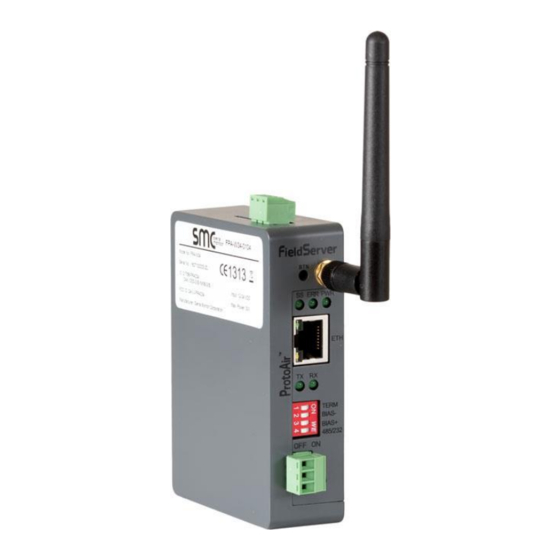
Siemens ProtoAir Start-up Guide INTRODUCTION ProtoAir Gateway The ProtoAir wireless gateway is an external, high performance building automation multi-protocol gateway that is preconfigured to auto-discover any of Siemens’ products (hereafter called “device”) connected to the ProtoAir and automatically configures them for BACnet/IP, Modbus TCP/IP and EtherNet/IP. -
Page 8: Protoair Setup
Siemens ProtoAir Start-up Guide PROTOAIR SETUP Record Identification Data Each ProtoAir has a unique part number located on the side or the back of the unit. This number should be recorded, as it may be required for technical support. The numbers are as follows: Model Part Number ProtoAir... -
Page 9: Configuring Device Communications
Siemens ProtoAir Start-up Guide Configuring Device Communications 3.3.1 Input COM Settings on the Device Connected to the ProtoAir • The connected serial device MUST have the same baud rate, data bits, stop bits, and parity settings as the ProtoAir. • specifies the device serial port settings required to communicate with the ProtoAir. -
Page 10: Interfacing Protoair To Devices
Siemens ProtoAir Start-up Guide INTERFACING PROTOAIR TO DEVICES Device Connections to ProtoAir • Connect the RS-485 network wires to the 3-pin RS-485 connector on the ProtoAir. (Figure Use standard grounding principles for RS-485 GND ProtoAir Wiring Pin # Assignment RS-485 + Pin 1 RS-485 + RS-485 -... -
Page 11: Bias Resistor Dip Switches
Siemens ProtoAir Start-up Guide 4.1.1 Bias Resistor DIP Switches Bias Resistor DIP Switches (2 and 3) Figure 7: Bias Resistors To enable Bias Resistors, move both the BIAS- and BIAS+ dip switches to the right. The ProtoAir bias resistors are used to keep the RS-485 bus to a known state, when there is no transmission on the line (bus is idling), to help prevent false bits of data from being detected. -
Page 12: Termination Resistor
Siemens ProtoAir Start-up Guide 4.1.2 Termination Resistor Termination Resistor DIP Switch (1) Figure 8: Termination Resistor If the ProtoAir is the last device on the Serial trunk, then the End-Of-Line Termination Switch needs to be enabled. To enable the Termination Resistor, move the TERM dip switch to the right. Termination resistor is also used to reduce noise. -
Page 13: Power-Up Protoair
Siemens ProtoAir Start-up Guide Power-Up ProtoAir Check power requirements in the table below: Power Requirement for ProtoAir External Gateway Current Draw Type ProtoAir Family 12V DC 24V DC FPA – W34 (Typical) 170mA 100mA FPA – W34 (Maximum) 240mA 140mA NOTE: These values are ‘nominal’... -
Page 14: Connect The Pc To The Protoair Over Ethernet Or Wi-Fi
Siemens ProtoAir Start-up Guide CONNECT THE PC TO THE PROTOAIR OVER ETHERNET OR WI-FI Connecting to the ProtoAir via Ethernet First, connect a CAT5 Ethernet cable (straight through or cross-over) between the local PC and ProtoAir. Ethernet Port Figure 11: Ethernet Port Location There are two ways to access the ProtoAir via an Ethernet connection, either by changing the subnet of the connected PC or using the FieldServer Toolbox to change the IP Address of the ProtoAir. -
Page 15: Changing The Ip Address Of The Protoair With Fieldserver Toolbox
Siemens ProtoAir Start-up Guide 5.1.2 Changing the IP Address of the ProtoAir with FieldServer Toolbox • Ensure that FieldServer Toolbox is loaded onto the local PC. Otherwise, download the FieldServer-Toolbox.zip via the Sierra Monitor Resource Center Software Downloads. • Extract the executable file and complete the installation. •... -
Page 16: Connecting To The Protoair Via Wi-Fi Access Point
Siemens ProtoAir Start-up Guide Connecting to the ProtoAir via W i-Fi Access Point When the ProtoAir is first powered up the Wi-Fi access point will be enabled allowing direct connection to the ProtoAir via Wi-Fi. To connect to the ProtoAir Wi-Fi access point: •... -
Page 17: Updating Network Settings
Siemens ProtoAir Start-up Guide Updating Network Settings 5.3.1 Navigate to the FS-GUI Network Settings After setting a local PC on the same subnet as the ProtoAir (Section or Section 5.2), open a web browser on the PC and enter the IP Address of the ProtoAir; the default Ethernet address is 192.168.1.24, the default Wi-Fi access point address is 192.168.50.1. -
Page 18: Figure 14: Generic Fs-Gui Navigation Panel - Network Settings
Siemens ProtoAir Start-up Guide • Click the orange arrow next to the ProtoAir CN number and title to expand the tree. • Click on the orange arrow next to Setup to expand the tree. • Click on Network Settings. Figure 14: Generic FS-GUI Navigation Panel – Network Settings Page 18 of 43... -
Page 19: Ip Settings
Siemens ProtoAir Start-up Guide 5.3.2 IP Settings IP Settings tab is the landing page when selecting Network Settings on the navigation tree. To change the IP settings, follow these instructions: • Enable DHCP Client State to automatically assign IP Settings or modify the settings manually as needed, via these fields: IP Address, Netmask, Default Gateway and Domain Name Server1/2. -
Page 20: Wi-Fi Client Settings
Siemens ProtoAir Start-up Guide 5.3.3 Wi-Fi Client Settings From the FS-GUI Network Settings landing page, click on the Wi-Fi Client tab. To change the Wi-Fi client settings, follow these instructions: • The Wi-Fi Status field must be set to ENABLED to allow the ProtoAir to communicate with other devices via Wi-Fi. -
Page 21: Wi-Fi Ap - Access Point Settings
Siemens ProtoAir Start-up Guide 5.3.4 Wi-Fi AP – Access Point Settings From the FS-GUI Network Settings landing page, click on the Wi-Fi AP tab. To change the Wi-Fi AP settings, follow these instructions: • The Access Point Status Field must be ENABLED to allow connecting to the ProtoAir via Wi-Fi. •... -
Page 22: Common Settings
Siemens ProtoAir Start-up Guide 5.3.5 Common Settings From the FS-GUI Network Settings landing page, click on the Common tab. To change the primary connection when both Ethernet and Wi-Fi Client connections are available: • Select the desired option from the drop-down menu on the right. •... -
Page 23: Configure The Protoair
Siemens ProtoAir Start-up Guide CONFIGURE THE PROTOAIR • Follow the steps outlined in Section to access the ProtoAir Web Configurator. • To set the ProtoAir protocol setup, select the desired setup via the Protocol Selector parameter, click submit and then click System Restart once prompted. •... -
Page 24: Figure 20: Web Configurator Showing Active Profile Additions
Siemens ProtoAir Start-up Guide • To add an active profile to support a device, click the Add button under the Active Profiles heading. This will present a drop-down box underneath the Current profile column that lists all the available profiles. For every device that is added, assign a unique Node-ID. -
Page 25: Bacnet: Setting Node_Offset To Assign Specific Device Instances
Siemens ProtoAir Start-up Guide BACNET: SETTING NODE_OFFSET TO ASSIGN SPECIFIC DEVICE INSTANCES • Follow the steps outlined in Section to access the ProtoAir Web Configurator. • Node_Offset field shows the current value (default = 50,000). The values allowed for a BACnet Device Instance can range from 1 to 4,194,303 •... -
Page 26: How To Start The Installation Over: Clearing Profiles
Siemens ProtoAir Start-up Guide HOW TO START THE INSTALLATION OVER: CLEARING PROFILES • Follow the steps outlined in Section to access the ProtoAir Web Configurator. • At the bottom-left of the page, click the “Clear Profiles and Restart” button. • Once restart is complete, all past profiles discovered and/or added via Web Configurator are deleted. -
Page 27: Appendix A. Troubleshooting
Siemens ProtoAir Start-up Guide Appendix A. Troubleshooting Appendix A.1. Lost or Incorrect IP Address • Ensure that FieldServer Toolbox is loaded onto the local PC. Otherwise, download the FieldServer-Toolbox.zip via the Sierra Monitor Resource Center Software Downloads. • Extract the executable file and complete the installation. Ethernet Port Figure 23: Ethernet Port Location •... -
Page 28: Appendix A.2. Viewing Diagnostic Information
Siemens ProtoAir Start-up Guide Appendix A.2. Viewing Diagnostic Information • Type the IP Address of the ProtoAir into the web browser or use the FieldServer Toolbox to connect to the ProtoAir. • Click on Diagnostics and Debugging Button, then click on view, and then on connections. •... -
Page 29: Appendix A.3. Checking Wiring And Settings
Siemens ProtoAir Start-up Guide Appendix A.3. Checking Wiring and Settings • No COMS on Modbus RTU side. If the Tx/Rx LEDs are not flashing rapidly then there is a COM issue. To fix this, check the following: Visual observations of LEDs on ProtoAir (Appendix A.4) Check baud rate, parity, data bits, stop bits... -
Page 30: Appendix A.4. Led Diagnostics For Communications Between Protoair And Devices
Siemens ProtoAir Start-up Guide Appendix A.4. LED Diagnostics for Communications Between ProtoAir and Devices See the diagram below for ProtoAir LED Locations. Diagnostic LEDs Description The SPL LED will light if the unit is not getting a response from one or more of the configured devices. The SYS ERR LED will go on solid indicating there is a system error. - Page 31 Siemens ProtoAir Start-up Guide • Step 1: Take a Log Click on the diagnose icon of the desired device Ensure “Full Diagnostic” is selected (this is the default) NOTE: If desired, the default capture period can be changed. Page 31 of 43...
- Page 32 Siemens ProtoAir Start-up Guide Click on “Start Diagnostic” Wait for Capture period to finish, then the Diagnostic Test Complete window will appear • Step 2: Send Log Once the Diagnostic test is complete, a .zip file is saved on the PC Choose “Open”...
-
Page 33: Appendix A.6. Take A Diagnostic Capture Via Fs-Gui
Siemens ProtoAir Start-up Guide Appendix A.6. Take a Diagnostic Capture via FS-GUI Diagnostic Capture via FS-GUI is only available on FieldServers with a bios updated/released on November 2017 or later. Completing a Diagnostic Capture through the FieldServer allows network connections (such as Ethernet and Wi-Fi) to be captured. Once the Diagnostic Capture is complete, email it to technical support. -
Page 34: Appendix A.7. Wi-Fi Signal Strength
Siemens ProtoAir Start-up Guide Appendix A.7. Wi-Fi Signal Strength Wi-Fi <60dBm – Excellent <70dBm – Very good <80dBm – Good >80dBm – Weak Figure 27: Wi-Fi Signal Strength Listing NOTE: If the signal is weak or spotty, try to improve the signal strength by checking the antenna and the ProtoAir position. -
Page 35: Appendix B. Additional Information
Siemens ProtoAir Start-up Guide Appendix B. Additional Information Appendix B.1. Updating Firmware To load a new version of the firmware, follow these instructions: 1. Extract and save the new file onto the local PC. 2. Open a web browser and type the IP Address of the FieldServer in the address bar. NOTE: Default IP Address is 192.168.1.24 NOTE: Use the FS Toolbox utility if the IP Address is unknown (Appendix... -
Page 36: Appendix B.3. Securing Protoair With Passwords
Siemens ProtoAir Start-up Guide Appendix B.3. Securing ProtoAir with Passwords Access to the ProtoAir can be restricted by enabling a password. There are 2 access levels defined by 2 account names: Admin and User. • The Admin account has unrestricted access to the ProtoAir. •... -
Page 37: Appendix B.4. Mounting
Siemens ProtoAir Start-up Guide Appendix B.4. Mounting The ProtoAir can be mounted using the DIN rail mounting bracket on the back of the unit. Din Rail Bracket Figure 31: DIN Rail Page 37 of 43... -
Page 38: Appendix B.5. Physical Dimension Drawings
Siemens ProtoAir Start-up Guide Appendix B.5. Physical Dimension Drawings Power Port Wi-Fi Antenna Socket P1 Serial Port Figure 32: ProtoAir FPA-W34 Dimensions Page 38 of 43... -
Page 39: Appendix C. Vendor Information - Siemens
Siemens ProtoAir Start-up Guide Appendix C. Vendor Information – Siemens NOTE: All Modbus TCP/IP registers are the same as the Modbus RTU registers for the serial device. If this point list is needed, contact Siemens technical support. The Modbus TCP/IP node address of the device is also the same as the Modbus RTU node address. - Page 40 Siemens ProtoAir Start-up Guide Batch overrun on/off Batch overrun error Batch counter up/down Batch Time constants Batch cycle counter Cleaning cycle time Volume per pulse Pulse Polarity Pulse Timeout Input Function Totalizer reset Force output Sensor size Calibration factor Correction factor Excitation frequency Operating time Error pending list Reg 01...
- Page 41 Siemens ProtoAir Start-up Guide Error log list Reg 27 Language Display line 1 Display line 2 Display line 3 Volumeflow unit Volumeflow point Totalizer 1 unit Totalizer 1 point Totalizer 2 unit Totalizer 2 point System status SystemStatus_XXX Error pending 1 Error pending 2 Error pending 3 Error pending 4...
-
Page 42: Appendix D. Reference
Siemens ProtoAir Start-up Guide Appendix D. Reference Appendix D.1. Specifications ProtoAir FPA-W34 One 3-pin Phoenix connector with: RS-485 (Tx+ / Rx- / gnd) One 3-pin Phoenix connector with: Power port (+ / - / Frame-gnd) Electrical Connections One Ethernet 10/100 BaseT port... -
Page 43: Appendix E. Limited 2 Year Warranty
Siemens ProtoAir Start-up Guide Appendix E. Limited 2 Year Warranty Sierra Monitor Corporation warrants its products to be free from defects in workmanship or material under normal use and service for two years after date of shipment. Sierra Monitor Corporation will repair or replace any equipment found to be defective during the warranty period.