Table of Contents
Advertisement
Quick Links
ProtoNode FPC-N54
Start-up Guide
For Interfacing Lochinvar Products:
SYNC™, Knight®/Knight XL®/Armor/Wall Mount/Wall Hung, Crest®, Copper-
Fin II®, Power Fin, Knight FTXL, Power Fin 2.5-5.0, IPW, Armor_1250_4000
To Building Automation Systems:
BACnet MS/TP, BACnet/IP, Modbus TCP/IP, Metasys N2 and SMC Cloud
APPLICABILITY & EFFECTIVITY
Explains ProtoNode hardware and installation.
The instructions are effective for the above as of June 2020.
Document Revision: 5.A
Web Configurator
Template Revision: 4
Advertisement
Table of Contents

Related Manuals for SMC Networks Lochinvar ProtoNode


Summary of Contents for SMC Networks Lochinvar ProtoNode
- Page 1 ProtoNode FPC-N54 Start-up Guide For Interfacing Lochinvar Products: SYNC™, Knight®/Knight XL®/Armor/Wall Mount/Wall Hung, Crest®, Copper- Fin II®, Power Fin, Knight FTXL, Power Fin 2.5-5.0, IPW, Armor_1250_4000 To Building Automation Systems: BACnet MS/TP, BACnet/IP, Modbus TCP/IP, Metasys N2 and SMC Cloud APPLICABILITY &...
- Page 2 Lochinvar ProtoNode Start-up Guide Technical Support Thank you for purchasing the ProtoNode for Lochinvar. Please call Lochinvar for technical support of the ProtoNode product. MSA Safety does not provide direct support. If Lochinvar needs to escalate the concern, they will contact MSA Safety for assistance.
- Page 3 Lochinvar ProtoNode Start-up Guide Quick Start Guide 1. Record the information about the unit. (Section 3.1) 2. Check that the ProtoNode and customer device COM settings match. (Section 3.3) 3. Connect the ProtoNode 3 pin RS-485 R1 port to the RS-485 network connected to each of the devices.
-
Page 4: Table Of Contents
Lochinvar ProtoNode Start-up Guide TABLE OF CONTENTS Certification ............................7 BTL Mark – BACnet ® Testing Laboratory ..................7 Introduction ............................8 ProtoNode Gateway ........................8 ProtoNode Setup ..........................9 Record Identification Data ......................9 Point Count Capacity ........................9 Configuring Device Communications ................... - Page 5 Lochinvar ProtoNode Start-up Guide Appendix B.9.2 Edit Users ........................44 Appendix B.9.3 Delete Users ....................... 45 Appendix B.10 Change General Password ..................... 46 Appendix C Vendor Information – Lochinvar ..................47 Appendix C.1 SYNC Modbus RTU Mappings to BACnet and Metasys N2 ..........47 Appendix C.2 Knight/Knight XL/Armor/Wall Mount/Wall Hung Modbus RTU Mappings to BACnet and...
- Page 6 Lochinvar ProtoNode Start-up Guide LIST OF FIGURES Figure 1: ProtoNode Part Numbers ......................9 Figure 2: Supported Point Count Capacity ....................9 Figure 3: Points per Device ........................... 9 Figure 4: COM Settings ..........................10 Figure 5: Lochinvar Modbus COM Board Showing Serial DIP Switches ............ 10 Figure 6: RS-485 Connections from Devices to the ProtoNode ..............
-
Page 7: Certification
Lochinvar ProtoNode Start-up Guide CERTIFICATION BTL Mark – BACnet ® 1 Testing Laboratory The BTL Mark on ProtoNode is a symbol that indicates that a product has passed a series of rigorous tests conducted by an independent laboratory which verifies that the product correctly implements the BACnet features claimed in the listing. -
Page 8: Introduction
Lochinvar ProtoNode Start-up Guide INTRODUCTION ProtoNode Gateway The ProtoNode is an external, high performance building automation multi-protocol gateway that is preconfigured to automatically communicate between Lochinvar’s devices (hereafter simply called “device”) connected to the ProtoNode and automatically configures them for BACnet/IP, BACnet MS/TP, Modbus ®2... -
Page 9: Protonode Setup
Lochinvar ProtoNode Start-up Guide PROTONODE SETUP Record Identification Data Each ProtoNode has a unique part number located on the side or the back of the unit. This number should be recorded, as it may be required for technical support. The numbers are as follows:... -
Page 10: Configuring Device Communications
Lochinvar ProtoNode Start-up Guide Configuring Device Communications 3.3.1 Confirm the Device and ProtoNode COM Settings Match • Any connected serial devices MUST have the same baud rate, data bits, stop bits, and parity settings as the ProtoNode. • Figure 4 specifies the device serial port settings required to communicate with the ProtoNode. -
Page 11: Interfacing Protonode To Devices
Lochinvar ProtoNode Start-up Guide INTERFACING PROTONODE TO DEVICES Device Connections to ProtoNode The ProtoNode has a 3-pin Phoenix connector for connecting RS-485 devices on the R1 port. NOTE: Use standard grounding principles for RS-485 GND. ProtoNode Device Pins Pin Label... -
Page 12: Bias Resistors
Lochinvar ProtoNode Start-up Guide Bias Resistors R1 Bias Resistor DIP Switches (2 and 3) R2 Bias Resistor DIP Switches (2 and 3) Figure 8: Bias Resistor DIP Switches To enable Bias Resistors, move both the BIAS- and BIAS+ dip switches to the right as shown in... -
Page 13: Termination Resistor
Lochinvar ProtoNode Start-up Guide Termination Resistor R1 Termination Resistor DIP Switch (1) R2 Termination Resistor DIP Switch (1) Figure 9: Termination Resistor DIP Switch If the ProtoNode is the last device on the serial trunk, then the End-Of-Line Termination Switch needs to be enabled. -
Page 14: Power-Up Protonode
Lochinvar ProtoNode Start-up Guide Power-Up ProtoNode Check power requirements in the table below: Power Requirement for ProtoNode External Gateway Current Draw Type ProtoNode Family 12VDC 24VDC/AC FPC – N54 (Typical) 250mA 125mA NOTE: These values are ‘nominal’ and a safety margin should be added to the power supply of the host system. -
Page 15: Connect The Pc To The Protonode
Lochinvar ProtoNode Start-up Guide CONNECT THE PC TO THE PROTONODE Connecting to the ProtoNode via Ethernet Connect a Cat-5 Ethernet cable (straight through or cross-over) between the local PC and ProtoNode. Ethernet Port Figure 12: Ethernet Port Location 5.1.1 Changing the Subnet of the Connected PC The default IP Address for the ProtoNode is 192.168.1.24, Subnet Mask is 255.255.255.0. -
Page 16: Setup Web Server Security
Lochinvar ProtoNode Start-up Guide SETUP WEB SERVER SECURITY Navigate to the IP Address of the ProtoNode on the local PC by opening a web browser and entering the IP Address of the ProtoNode; the default Ethernet address is 192.168.1.24. NOTE: If the IP Address of the ProtoNode has been changed, the IP Address can be discovered using the FS Toolbox utility. -
Page 17: Figure 15: Warning Expanded Text
Lochinvar ProtoNode Start-up Guide • Additional text will expand below the warning, click the underlined text to go to the IP Address. In Figure 15 example this text is “Proceed to 10.40.50.94 (unsafe)”. Figure 15: Warning Expanded Text • When the login screen appears, put in the Username (default is “admin”) and the Password (found on the label of the FieldServer). -
Page 18: Select The Security Mode
Lochinvar ProtoNode Start-up Guide Select the Security Mode • On the first login to the FieldServer, the following screen will appear that allows the user to select which mode the FieldServer should use. Figure 17: Security Mode Selection Screen NOTE: Cookies are used for authentication. -
Page 19: 6.2.1 Https With Own Trusted Tls Certificate
Lochinvar ProtoNode Start-up Guide 6.2.1 HTTPS with Own Trusted TLS Certificate This is the recommended selection and the most secure. • Once this option is selected, the Certificate, Private Key and Private Key Passphrase fields will appear under the mode selection. -
Page 20: Configure The Protonode
Lochinvar ProtoNode Start-up Guide CONFIGURE THE PROTONODE Select Field Protocol and Set Configuration Parameters • On the Web Configurator page, the first configuration parameter is the Protocol Selector. Figure 19: Web Configurator Showing Protocol Selector Parameter • Select the field protocol by entering the appropriate number into the Protocol Selector Value. Click the Submit button. -
Page 21: Setting Protonode Active Profiles
Lochinvar ProtoNode Start-up Guide Setting ProtoNode Active Profiles • In the Web Configurator, the Active Profiles are shown below the configuration parameters. The Active Profiles section lists the currently active device profiles, including previous Web Configurator additions. This list is empty for new installations, or after clearing all configurations. -
Page 22: Verify Device Communications
Lochinvar ProtoNode Start-up Guide • To add an active profile to support a device, click the Add button under the Active Profiles heading. This will present a profile drop-down menu underneath the Current profile column. (Figure Figure 21: Web Configurator Active Profile Selection •... -
Page 23: Ethernet Network: Setting Ip Address For The Field Network
Lochinvar ProtoNode Start-up Guide Ethernet Network: Setting IP Address for the Field Network • Follow the steps outlined in Section to access the ProtoNode Web Configurator. • To access the FS-GUI, click on the “Diagnostics & Debugging” button. Figure 23: Web Configurator Screen... -
Page 24: Figure 24: Changing Ip Address Via Fs-Gui
Lochinvar ProtoNode Start-up Guide • From the FS-GUI landing page, click on “Setup” to expand the navigation tree and then select “Network Settings” to access the IP Settings menu. (Figure Figure 24: Changing IP Address via FS-GUI • Modify the IP Address (N1 IP Address field) of the ProtoNode Ethernet port. -
Page 25: Bacnet: Setting Node_Offset To Assign Specific Device Instances
Lochinvar ProtoNode Start-up Guide BACnet: Setting Node_Offset to Assign Specific Device Instances • Follow the steps outlined in Section to access the ProtoNode Web Configurator. • Node_Offset field shows the current value (default = 50,000). The values allowed for a BACnet Device Instance can range from 1 to 4,194,303 •... -
Page 26: How To Start The Installation Over: Clearing Profiles
Lochinvar ProtoNode Start-up Guide How to Start the Installation Over: Clearing Profiles • Follow the steps outlined in Section to access the ProtoNode Web Configurator. • At the bottom-left of the page, click the “Clear Profiles and Restart” button. •... -
Page 27: Appendix A Troubleshooting
Lochinvar ProtoNode Start-up Guide Appendix A Troubleshooting Appendix A.1 Lost or Incorrect IP Address • Ensure that FieldServer Toolbox is loaded onto the local PC. Otherwise, download the FieldServer-Toolbox.zip via the Sierra Monitor website’s Software Downloads. • Extract the executable file and complete the installation. -
Page 28: Appendix A.2 Viewing Diagnostic Information
Lochinvar ProtoNode Start-up Guide Appendix A.2 Viewing Diagnostic Information • Type the IP Address of the ProtoNode into the web browser or use the FieldServer Toolbox to connect to the ProtoNode. • Click on Diagnostics Button, then click on view, and then on connections. -
Page 29: Appendix A.3 Checking Wiring And Settings
Lochinvar ProtoNode Start-up Guide Appendix A.3 Checking Wiring and Settings • No COMS on Modbus RTU side. If the Tx/Rx LEDs are not flashing rapidly then there is a COM issue. To fix this, check the following: A.4) Visual observations of LEDs on ProtoNode... -
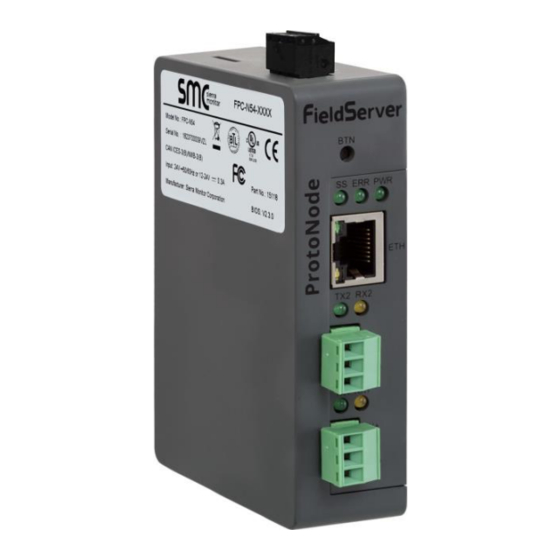
Page 30: Appendix A.4 Led Diagnostics For Communications Between Protonode And Devices
Lochinvar ProtoNode Start-up Guide Appendix A.4 LED Diagnostics for Communications Between ProtoNode and Devices See the diagram below for ProtoNode FPC-N54 LED Locations. FPC-N54 Diagnostic LEDs Description The SS LED will flash once a second to indicate that the bridge is in operation. -
Page 31: Appendix A.5 Take A Fieldserver Diagnostic Capture
Lochinvar ProtoNode Start-up Guide Appendix A.5 Take a FieldServer Diagnostic Capture When there is a problem on-site that cannot easily be resolved, perform a diagnostic capture before contacting support so that support can quickly solve the problem. There are two methods for taking diagnostic captures: •... - Page 32 Lochinvar ProtoNode Start-up Guide • Step 1: Take a Log Click on the diagnose icon of the desired device Ensure “Full Diagnostic” is selected (this is the default) NOTE: If desired, the default capture period can be changed. Page 32 of 56...
- Page 33 Lochinvar ProtoNode Start-up Guide Click on “Start Diagnostic” Wait for Capture period to finish, then the Diagnostic Test Complete window will appear • Step 2: Send Log Once the Diagnostic test is complete, a .zip file is saved on the PC Choose “Open”...
-
Page 34: Appendix A.5.2 Using Fs-Gui
Lochinvar ProtoNode Start-up Guide Appendix A.5.2 Using FS-GUI Completing a Diagnostic Capture through the FieldServer allows network connections (such as Ethernet and Wi-Fi) to be captured. Once the Diagnostic Capture is complete, email it to technical support. The Diagnostic Capture will accelerate diagnosis of the problem. -
Page 35: Appendix B Additional Information
Lochinvar ProtoNode Start-up Guide Appendix B Additional Information Appendix B.1 Updating Firmware To load a new version of the firmware, follow these instructions: 1. Extract and save the new file onto the local PC. 2. Open a web browser and type the IP Address of the FieldServer in the address bar. -
Page 36: Appendix B.3 Securing Protonode With Passwords
Lochinvar ProtoNode Start-up Guide Appendix B.3 Securing ProtoNode with Passwords Access to the ProtoNode can be restricted by enabling a password on the FS-GUI Passwords page – click Setup and then Passwords in the navigation panel. There are 2 access levels defined by 2 account names: Admin and User. -
Page 37: Appendix B.4 Factory Reset Instructions
Lochinvar ProtoNode Start-up Guide Appendix B.4 Factory Reset Instructions For instructions on how to reset a FieldServer back to its factory released state, see ENOTE - FieldServer Next Gen Recovery. Appendix B.5 Internet Browser Software Support The following web browsers are supported: •... -
Page 38: Appendix B.7 Physical Dimension Drawing
Lochinvar ProtoNode Start-up Guide Appendix B.7 Physical Dimension Drawing Power Port R2 Serial Port R1 Serial Port Figure 35: ProtoNode FPC-N54 Dimensions Page 38 of 56... -
Page 39: Appendix B.8 Change Web Server Security Settings After Initial Setup
Lochinvar ProtoNode Start-up Guide Appendix B.8 Change Web Server Security Settings After Initial Setup • Type the IP Address of the ProtoCessor into the web browser or use the FieldServer Toolbox to connect to the ProtoCessor, then login to the FieldServer. -
Page 40: Appendix B.8.1 Change Security Mode
Lochinvar ProtoNode Start-up Guide Appendix B.8.1 Change Security Mode • Click Security in the Navigation panel. Figure 37: FS-GUI Security Setup • Click the Mode desired. If changing the security mode to HTTPS with own trusted TLS certificate, follow instructions in 6.2.1... -
Page 41: Appendix B.8.2 Edit The Certificate Loaded Onto The Fieldserver
Lochinvar ProtoNode Start-up Guide Appendix B.8.2 Edit the Certificate Loaded onto the FieldServer NOTE: A loaded certificate will only be available if the security mode was previously setup as HTTPS with own trusted TLS certificate. • Click Security in the Navigation panel. -
Page 42: Appendix B.9 Create And Manage Individual Users
Lochinvar ProtoNode Start-up Guide Appendix B.9 Create and Manage Individual Users • Type the IP Address of the ProtoCessor into the web browser or use the FieldServer Toolbox to connect to the ProtoCessor, then login to the FieldServer. • Click on the Diagnostics tab at the top of the screen, then click on View in the navigation panel, and then on Connections. -
Page 43: Appendix B.9.1 Create Users
Lochinvar ProtoNode Start-up Guide Appendix B.9.1 Create Users • Click the Create User button. Figure 40: Create User Window • Enter the new User fields: Name, Security Group and Password. User details are hashed and salted. NOTE: Passwords must be at least 10 characters long. An algorithm automatically checks the password entered and notes the level of strength on the top right of the Password text field. -
Page 44: Appendix B.9.2 Edit Users
Lochinvar ProtoNode Start-up Guide Appendix B.9.2 Edit Users • Click the pencil icon next to the desired user to open the User Edit window. Figure 41: Setup Users • Once the User Edit window opens, change the User Security Group and Password as needed. -
Page 45: Appendix B.9.3 Delete Users
Lochinvar ProtoNode Start-up Guide Appendix B.9.3 Delete Users • Click the trash can icon next to the desired user to delete the entry. Figure 43: Setup Users • When the warning message appears, click Confirm. Figure 44: User Delete Warning... -
Page 46: Appendix B.10 Change General Password
Lochinvar ProtoNode Start-up Guide Appendix B.10 Change General Password • Type the IP Address of the ProtoCessor into the web browser or use the FieldServer Toolbox to connect to the ProtoCessor, then login to the FieldServer. • Click on the Diagnostics tab at the top of the screen, then click on View in the navigation panel, and then on Connections. -
Page 47: Appendix C Vendor Information - Lochinvar
Lochinvar ProtoNode Start-up Guide Appendix C Vendor Information – Lochinvar NOTE: All Modbus TCP/IP registers are the same as the Modbus RTU registers for the serial device. If this point list is needed, contact technical support. The Modbus TCP/IP node address of the device is also the same as the Modbus RTU node address. -
Page 48: Appendix C.2 Knight/Knight Xl/Armor/Wall Mount/Wall Hung Modbus Rtu Mappings To Bacnet And Metasys N2
Lochinvar ProtoNode Start-up Guide 0-10 Volt Input/Rate Cmd/SP Cmd Tank Setpoint Tank Temperature Outdoor Temperature System Supply Temperature Appendix C.2 Knight/Knight XL/Armor/Wall Mount/Wall Hung Modbus RTU Mappings to BACnet and Metasys N2 BACnet BACnet N2 Data Point Name Object Type... - Page 49 Lochinvar ProtoNode Start-up Guide Manual Reset High Limit Flow Switch Gas Pressure Switch Louvers Proving Switch Blower Proving Switch 1 Blocked Drain Switch Flame 1 Enable Tank Thermostat Blocked Flue Blower Proving Switch 2 Flue Damper Proving Switch Flame 2...
-
Page 50: Appendix C.4 Copper-Fin Ii Modbus Rtu Mappings To Bacnet And Metasys N2
Lochinvar ProtoNode Start-up Guide Appendix C.4 Copper-Fin II Modbus RTU Mappings to BACnet and Metasys N2 BACnet BACnet N2 Data Point Name Object Type Object ID Type Address Stage 1 Enable Stage 2 Enable Stage 3 Enable Stage 4 Enable... -
Page 51: Appendix C.6 Knight Ftxl Modbus Rtu Mappings To Bacnet And Metasys N2
Lochinvar ProtoNode Start-up Guide Gas Pressure Switch 1 Louver Proving Switch 1 Air Pressure Switch/Flap Vlv 1 Blocked Drain Switch 1 Auto Reset High Limit 1 Flame 1 Enable/Room Thermostat 1/Stg 1 Tank Thermostat Run-time Contacts Alarm Contacts 1 CH Pump 1... -
Page 52: Appendix C.7 Power Fin 2.5-5.0 Modbus Rtu Mappings To Bacnet And Metasys N2
Lochinvar ProtoNode Start-up Guide System Pump DHW Pump 2 Discrete Inputs 1 - 16 Discrete Inputs 17 - 32 Discrete Inputs 33 - 48 System Cascade Setpoint System Pump Speed Cascade Total Power Cascade Current Power Outlet Setpoint Outlet Temperature... -
Page 53: Appendix C.8 Ipw Modbus Rtu Mappings To Bacnet And Metasys N2
Lochinvar ProtoNode Start-up Guide Firing Rate 1 Boiler 1 Pump Speed Boiler 1 Status Code Boiler 1 Blocking Code Boiler 1 Lockout Code Discrete Inputs 49-64 Lockout Error Leader Lockout Error Member 1 Lockout Error Member 2 Lockout Error Member 3... - Page 54 Lochinvar ProtoNode Start-up Guide Status Code Blocking Code Lockout Code Discrete Inputs 49 - 64 Lockout Code Leader Lockout Code Member 1 Lockout Code Member 2 Lockout Code Member 3 Lockout Code Member 4 Lockout Code Member 5 Lockout Code Member 6...
-
Page 55: Appendix D Reference
Lochinvar ProtoNode Start-up Guide Appendix D Reference Appendix D.1 Specifications ProtoNode FPC-N54 One 3-pin Phoenix connector with: RS-485/RS-232 (Tx+ / Rx- / gnd) One 3-pin Phoenix connector with: RS-485 (Tx+ / Rx- / gnd) Electrical Connections One 3-pin Phoenix connector with: Power port (+ / - / Frame-gnd) -
Page 56: Appendix E Limited 2 Year Warranty
Lochinvar ProtoNode Start-up Guide Appendix E Limited 2 Year Warranty MSA Safety warrants its products to be free from defects in workmanship or material under normal use and service for two years after date of shipment. MSA Safety will repair or replace any equipment found to be defective during the warranty period.