
Related Manuals for SMC Networks FieldServer QuickServer FS-QS-12 0 Series


Summary of Contents for SMC Networks FieldServer QuickServer FS-QS-12 0 Series
- Page 1 FieldServer QuickServer Start-up Guide FS-QS-1010/1011/12X0/12X1 APPLICABILITY & EFFECTIVITY Effective for all systems manufactured after July 2016. Document Revision: 1.C...
- Page 2 QuickServer Start-Up Guide Technical Support Please call us for any technical support needs related to the FieldServer product. Sierra Monitor Corporation 1991 Tarob Court Milpitas, CA 95035 Website: www.sierramonitor.com U.S. Support Information: +1 408 262-6611 +1 800 727-4377 Email: support@sierramonitor.com EMEA Support Information: +44 2033 1813 41 Email:...
-
Page 3: Table Of Contents
QuickServer Start-Up Guide TABLE OF CONTENTS Table of Contents ............................3 List of Figures ............................. 5 Equipment Set-up ..........................6 Supplied equipment..........................6 Certifications ............................7 BTL Mark – BACnet Testing Laboratory..................7 LonMark Certification ........................7 Mounting ............................... 8 Dimensions ............................. - Page 4 QuickServer Start-Up Guide Appendix A.5. SSL/TLS for Secure Connection ..................34 Appendix A.5.1. Configuring FieldServer as a SSL/TLS Server ............34 Appendix A.5.2. Configuring FieldServer as SSL/TLS Client .............. 37 Appendix B Troubleshooting Tips ......................38 Appendix B.1. Communicating with the QuickServer over the Network ..........38 Appendix B.2.
-
Page 5: List Of Figures
QuickServer Start-Up Guide LIST OF FIGURES Figure 1: DIN Rail ............................8 Figure 2: FS-QS-1X10-XXXX........................9 Figure 3: FS-QS-1XX1-XXXX ........................10 Figure 4: FS-QS-123X models with RS-422 ....................11 Figure 5: Bias Resistors ..........................12 Figure 6: Termination Resistor ........................13 Figure 7: Power Jumper Switch ........................ -
Page 6: Equipment Set-Up
QuickServer Start-Up Guide EQUIPMENT SET-UP QuickServer is a high performance, cost effective Building and Industrial Automation multi-protocol gateway providing protocol translation between serial, Ethernet, and LonWorks devices and networks. NOTE: For FieldPoP™ information, refer to the FieldPoP™ Device Cloud Start-up Guide online at the Sierra Monitor.com Resource Center. -
Page 7: Certifications
QuickServer Start-Up Guide CERTIFICATIONS BTL Mark – BACnet Testing Laboratory The BTL Mark is a symbol that indicates that a product has passed a series of rigorous tests conducted by an independent laboratory which verifies that the product correctly implements the BACnet features claimed in the listing. The mark is a symbol of a high-quality BACnet product. -
Page 8: Mounting
QuickServer Start-Up Guide MOUNTING The following mounting options are available: Product comes with tabs for wall or surface mount. These can be snapped off if not required. DIN Rail Mounting Bracket - included in the accessory kit or ordered separately (part # FS-8915-35- QS). -
Page 9: Dimensions
QuickServer Start-Up Guide Dimensions 4.1.1 Dimension Drawing FS-QS-1X10-XXXX R1 Port R2 Port Figure 2: FS-QS-1X10-XXXX Page 9 of 46... -
Page 10: Dimension Drawing Fs-Qs-1Xx1-Xxxx
QuickServer Start-Up Guide 4.1.2 Dimension Drawing FS-QS-1XX1-XXXX LonWorks Port R2 Port Figure 3: FS-QS-1XX1-XXXX Page 10 of 46... -
Page 11: Dimension Drawing Fs-Qs-123X Models With Rs-422
QuickServer Start-Up Guide 4.1.3 Dimension Drawing FS-QS-123X Models with RS-422 R1 Port R2 Port Figure 4: FS-QS-123X models with RS-422 Page 11 of 46... -
Page 12: Wiring
QuickServer Start-Up Guide Wiring 4.2.1 Bias Resistors Bias Resistors Figure 5: Bias Resistors The QuickServer bias resistors are used to keep the RS-485 bus to a known state, when there is no transmission on the line (bus is idling), to help prevent false bits of data from being detected. The bias resistors typically pull one line high and the other low - i.e. -
Page 13: Termination Resistor
QuickServer Start-Up Guide 4.2.2 Termination Resistor Termination Resistor Figure 6: Termination Resistor Termination resistors are also used to reduce noise. These pull the two lines of an idle bus together. However, they would override the effect of any bias resistors, if connected. Page 13 of 46... -
Page 14: Power Jumper Settings
QuickServer Start-Up Guide 4.2.3 Power Jumper Settings Power Jumper Switch in position “A” Figure 7: Power Jumper Switch The QuickServer Carrier Board power jumper is set to position A by default, but can be changed to position B for other power supply requirements. Position A: The Carrier makes use of a full-wave rectifying bridge. -
Page 15: Specifications
QuickServer Start-Up Guide Specifications FS-QS-1010-XXXX/FS-QS-12X0-XXXX FS-QS-1011-XXXX/FS-QS-12X1-XXXX 6-pin Phoenix connector: RS-485 or RS- 6-pin Phoenix connector: RS-485 or RS-232 232 or RS-422 +/- ground port, power +/- or RS-422 +/- ground port, power +/- frame frame ground port ground port Available Ports 3-pin RS-485 Phoenix connector: RS-485 2-pin FTT-10 LonWorks port +/- ground port... -
Page 16: Installing The Quickserver
QuickServer Start-Up Guide INSTALLING THE QUICKSERVER RS-485 5.1.1 RS-485 Connection R2 port A- SG Figure 9: RS-485 R2 Connection Port Connect to the 3 pins on the left-hand-side of the 6 pin connector as shown. The following Baud Rates are supported on the R2 Port: 4800, 9600, 19200, 38400, 57600, 115200 For connection to RS-232 or RS-422, please refer to Appendix... -
Page 17: Quickserver Lonworks (Fs-Qs-1Xx1-Xxxx)
QuickServer Start-Up Guide QuickServer LonW orks (FS-QS-1XX1-XXXX) Connect the QuickServer to the LonWorks terminal using a twisted pair non-shielded cable. LonWorks Service Pin LonWorks Terminal Figure 11: LonWorks Commissioning and Port To commission the QuickServer LonWorks port, insert a small screwdriver in the commissioning hole on the face of the QuickServer’s enclosure to access the Service Pin. -
Page 18: Rs-232 Connection R2 Port (Only Available On Fs-Qs-122X Models)
QuickServer Start-Up Guide RS-232 Connection R2 Port (only available on FS-QS-122X Models) Figure 13: RS-232 R2 Connection Port Refer to Appendix A2 for further hardware connection options. The following Baud Rates are supported on the R2 Port: 4800, 9600, 19200, 38400, 57600, 115200 Page 18 of 46... -
Page 19: Operation
QuickServer Start-Up Guide OPERATION Power up the device Apply power to the device. Ensure that the power supply used complies with the specifications provided in. Ensure that the cable is grounded using the “Frame GND” terminal. The QuickServer is factory set for 9-30VDC or 12-24VAC. -
Page 20: Connecting To The Quickserver
QuickServer Start-Up Guide Connecting to the QuickServer 6.3.1 Using the Toolbox application to discover and connect to the QuickServer Install the Toolbox application from the USB drive or get it from the Sierra Monitor website: www.sierramonitor.com/customer-care/resource-center?filters=software-downloads Use the Toolbox application to find the QuickServer, and launch the Web GUI. NOTE: If the connect button is greyed out, the QuickServer’s IP Address must be set to be on the same network as the PC. -
Page 21: Set Ip Address Of The Quickserver
QuickServer Start-Up Guide Set IP Address of the QuickServer 6.4.1 Using the Toolbox Application to set the IP Address From the Toolbox main page, click on the setup icon (the gear picture). Select Network Settings. Modify the IP Address (N1 IP Address field) of the QuickServer Ethernet port. NOTE: If the QuickServer is connected to a router, the IP Gateway of the QuickServer should be set to the IP Address of that router. - Page 22 QuickServer Start-Up Guide Click “Update IP Settings”, then click on the “Change and Restart” to restart the Gateway and activate the new IP Address. Note that if the GUI was open in a browser, the browser will need to be pointed to the new IP Address of the QuickServer before the GUI will be accessible again.
-
Page 23: Using The Web Gui To Set The Ip Address
QuickServer Start-Up Guide 6.4.2 Using the Web GUI to set the IP Address From the GUI main home page, click on setup and then Network Settings to enter the Edit IP Address Settings menu. Modify the IP Address (N1 IP Address field) of the QuickServer Ethernet port. ... -
Page 24: Configuring The Quickserver
QuickServer Start-Up Guide CONFIGURING THE QUICKSERVER Retrieve the Sample Configuration File The configuration of the QuickServer is provided to the QuickServer’s operating system via a comma- delimited file called “CONFIG.CSV”. If a custom configuration was ordered, the QuickServer will be programmed with the relevant device registers in the Config.csv file for the first time start-up. -
Page 25: Load The Updated Configuration File
QuickServer Start-Up Guide Load the Updated Configuration file 7.3.1 Using the Toolbox application to load a configuration file From the Toolbox main page, click on the setup icon (the gear picture). Select File Transfer. Page 25 of 46... - Page 26 QuickServer Start-Up Guide Browse and select the .csv file, open, then click “Update Config”. Once download is complete, click the Restart Button (or simply cycle power to the QuickServer) to put the new file into operation. Note that it is possible to do multiple downloads to the QuickServer before resetting it.
-
Page 27: Using The Web Gui To Load A Configuration File
QuickServer Start-Up Guide 7.3.2 Using the Web GUI to Load a Configuration F ile In the main menu of the FS-GUI screen, click “Setup”, then “File Transfer” and finally “Update”. Browse and select the .csv file, open, then click “Submit”. Figure 19: Web GUI Loading Files ... -
Page 28: Retrieve The Configuation File For Modification Or Backup
QuickServer Start-Up Guide 7.3.3 Retrieve the Configuation File for Modification or Backup To get a copy of the configuration file for modifying or backing up a configuration on a local computer, do the following: In the main menu of the FS-GUI screen, click “Setup”, then “File Transfer”. Figure 20: Retrieve Configuration File ... -
Page 29: Test And Commission The Quickserver
QuickServer Start-Up Guide Test and Commission the QuickServer Connect the QuickServer to the third party device(s), and test the application. From the main menu of FS-GUI click on “View”, then “Connections” to see the number of messages on each protocol. Figure 21: Web GUI Connections ... -
Page 30: Appendix A Useful Features
QuickServer Start-Up Guide Appendix A Useful Features Appendix A.1. RS-422 Connection R2 Port (only available on the FS-QS-123X models) RS-422 is a full duplex multi-drop multi-master differential bus. It can be wired to conform to a RS-485 network when less wiring/cabling is used (due to being less expensive to install), but then it becomes a half-duplex multi-drop multi-master differential bus. -
Page 31: Appendix A.1.1. Connection And Operation Of The Rs-422 Quickserver
QuickServer Start-Up Guide Appendix A.1.1. Connection and Operation of the RS-422 QuickServer 5-pin RS-422 3-pin Power Connector Connector Figure 23: RS-422 Connectors RS-422 Connector Pin 1-2: TX +/- (Differential TX outputs: All + signals must be connected to each other, and same applies to - signals;... -
Page 32: Appendix A.2. Knx Connection R2 Port
QuickServer Start-Up Guide Appendix A.2. KNX Connection R2 Port The KNX QuickServer is used to transfer data to and from devices using KNX protocol. The KNX driver enables data access from KNX networks to other FieldServer protocols. Most KNX data-point types are supported, allowing communication to almost any kind of KNX device in an installation, such as temperature sensors, shutters, light switches, actuators, alarms, etc. -
Page 33: Appendix A.3. M-Bus Connection R2 Port
QuickServer Start-Up Guide Appendix A.3. M-Bus Connection R2 Port The M-Bus driver allows the FieldServer to transfer data to and from devices using M-Bus protocol. The Fieldbus connection is included with the FieldServer. The M-Bus QuickServer Gateway is configurable to act as both a Master and a Slave M-Bus device. -
Page 34: Appendix A.5. Ssl/Tls For Secure Connection
QuickServer Start-Up Guide Appendix A.5. SSL/TLS for Secure Connection SSL/TLS (Secure Sockets Layer/Transport Layer Security) is a security technology for establishing an encrypted connection between a server and a client. This allows the secure transfer of data across untrusted networks. These functions are supported on the following: FS-QS-1010 or FS-QS-1210 with a serial number starting with 14 or later (indicating the year it shipped). - Page 35 QuickServer Start-Up Guide Appendix A.5.1.2. Limiting Client Access In addition to TLS_Port parameter also add Validate_Client_Cert in the connections section of the configuration file and set it to “Yes”. Connections Adapter , Protocol , TLS_Port , Validate_Client_Cert , Modbus/TCP , 1502 , Yes The configuration above sets the FieldServer to request and verify a client’s certificate against its internal authority file before accepting connection.
- Page 36 QuickServer Start-Up Guide Appendix A.5.1.3. Certificate Validation Options If connections must be limited to only a particular domain (vendor devices), include Check_Remote_Host to specify the domain/host name. Connections Adapter , Protocol , TLS_Port , Validate_Client_Cert , Cert_Authority_File , Check_Remote_Host , Modbus/TCP , 1502 , Yes , my_authorized_clients.pem , SMC The configuration above tells the FieldServer to only accept connections that have the correct certification...
-
Page 37: Appendix A.5.2. Configuring Fieldserver As Ssl/Tls Client
QuickServer Start-Up Guide Appendix A.5.2. Configuring FieldServer as SSL/TLS Client The following Node configurations set the FieldServer to open a secure Modbus/TCP connection to Server at IP Address 10.11.12.13 on port 1502. Appendix A.5.2.1. Simple Secure Client Configuration Add Remote_Node_TLS_Port parameter in the nodes section of the configuration file and set to a port number between 1 –... -
Page 38: Appendix B Troubleshooting Tips
QuickServer Start-Up Guide Appendix B Troubleshooting Tips Appendix B.1. Communicating with the QuickServer over the Network Confirm that the network cabling is correct. Confirm that the computer network card is operational and correctly configured. Confirm that there is an Ethernet adapter installed in the PC’s Device Manager List, and that it is configured to run the TCP/IP protocol. - Page 39 QuickServer Start-Up Guide Disable any wireless Ethernet adapters on the PC/Laptop. Disable firewall and virus protection software if possible. Connect a standard CAT5 Ethernet cable between the PC and QuickServer. Double click on the FS Toolbox Utility. Step 1: Take a Log Click on the diagnose icon of the desired device...
- Page 40 QuickServer Start-Up Guide NOTE: If desired, the default capture period can be changed. Click on “Start Diagnostic” When the capture period is finished, the “Diagnostic Test Complete” window will appear Step 2: Send Log Once the diagnostic test is complete, a .zip file will be saved on the PC Click “Open”...
-
Page 41: Appendix B.3. Regarding Subnets And Subnet Masks
QuickServer Start-Up Guide Appendix B.3. Regarding Subnets and Subnet Masks RFC standards allocate the IP Address range of 192.0.0.0 through to 223.255.255.255 to be used in Class-C subnetting (i.e.: Subnets listed as 255.255.255.xxx, where xxx can vary based on filtering required). -
Page 42: Appendix C Limited 2 Year Warranty
QuickServer Start-Up Guide Appendix C Limited 2 year Warranty Sierra Monitor Corporation warrants its products to be free from defects in workmanship or material under normal use and service for two years after date of shipment. Sierra Monitor Corporation will repair or replace any equipment found to be defective during the warranty period. -
Page 43: Appendix D Reference
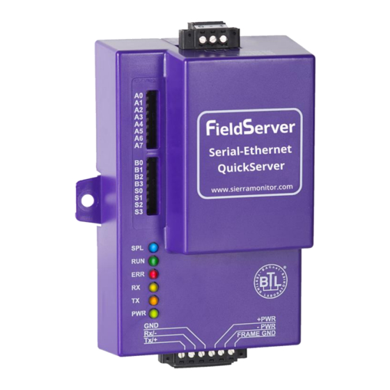
QuickServer Start-Up Guide Appendix D Reference Appendix D.1. LED Functions Figure 27: FS-QS-10XX LEDs Light Description SPL LED will be on when a configured node in the QuickServer is detected as being offline. See Node overview screen of the FS-GUI for further details. For LonWorks units, LED will light until the unit is commissioned on the LonWorks network. -
Page 44: Appendix D.2. Fs-Qs-1010-Xxxx Led Functions
QuickServer Start-Up Guide Appendix D.2. FS-QS-1010-XXXX LED Functions Figure 28: FS-QS-1010-XXXX LEDs Description The Run LED will start flashing 20 seconds after power indicating normal operation. The Heart Beat LED has the same functionality but flashes more rapidly. The Sys/Config Error LED will go on solid 15 seconds after power up. It will turn off after 5 Sys/ seconds. -
Page 45: Appendix D.3. Fs-Qs-1011-Xxxx Led Functions
QuickServer Start-Up Guide Appendix D.3. FS-QS-1011-XXXX LED Functions NOTE: The lid on top of the QuickServer has to be removed in order to see the LED’s. Figure 29: FS-QS-1011-XXXX LEDs Description The Run LED will start flashing 20 seconds after power indicating normal operation. The Heart Beat LED has the same functionality but flashes more rapidly. -
Page 46: Appendix D.4. Quickserver Fs-Qs-101X Dcc
QuickServer Start-Up Guide Appendix D.4. QuickServer FS-QS-101X DCC Driver Code BACnet/IP – BACnet MS/TP 0285 BACnet/IP – LonWorks 0131 – LonWorks JCI Metasys N2 0097 JCI Metasys N2– BACnet MS/TP 0309 JCI Metasys N2– BACnet/IP 0122 Modbus RTU – BACnet MS/TP 0367 Modbus RTU –...