Table of Contents
Advertisement
Quick Links
Instructions
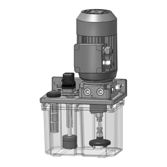
Injecto-Flo
Pump
Used for continuously pumping oil in circulating and hydrostatic oil lubrication systems
using progressive distributors.
Pump Part No.: 26A485
725 psi (5.0 MPa, 50 bar) Maximum Working Pressure
Important Safety Instructions
Read all warnings and instructions in this
manual. Save these instructions.
®
Oil
3A5213B
EN
Advertisement
Table of Contents

Related Manuals for Graco Injecto-Flo 26A485


Summary of Contents for Graco Injecto-Flo 26A485
- Page 1 Instructions ® Injecto-Flo Pump 3A5213B Used for continuously pumping oil in circulating and hydrostatic oil lubrication systems using progressive distributors. Pump Part No.: 26A485 725 psi (5.0 MPa, 50 bar) Maximum Working Pressure Important Safety Instructions Read all warnings and instructions in this manual.
- Page 2 Warnings Warnings The following warnings are for the setup, use, grounding, maintenance, and repair of this equipment. The exclama- tion point symbol alerts you to a general warning and the hazard symbols refer to procedure-specific risks. When these symbols appear in the body of this manual or on warning labels, refer back to these Warnings. Product-specific hazard symbols and warnings not covered in this section may appear throughout the body of this manual where applicable.
- Page 3 Warnings WARNING EQUIPMENT MISUSE HAZARD Misuse can cause death or serious injury. • Do not operate the unit when fatigued or under the influence of drugs or alcohol. • Do not exceed the maximum working pressure or temperature rating of the lowest rated system com- ponent.
-
Page 4: Installation
Installation Installation * To relieve pressure in the system, a 3-way valve must be installed in the outlet tubing. Component Identification Typical Circulation Lubrication See F . 1 and F System . 1: Hydraulic Diagram Tank Suction filter Gear pump Electric motor Pressure limiting valve Level switch... -
Page 5: Pressure Relief Procedure
Installation Installation Wiring Diagram All electrical wiring must be done by a qualified elec- trician and comply with all local codes and regula- tions. Instructions 1. Disconnect the power at the source. 2. Remove the 4 bolts from the cover to the junction box and remove the cover from the motor. -
Page 6: Operation
Operation Operation System Control Reed Switch Protection To protect the functionality of the reed switch, the cus- The system is controlled externally using a PLC or auto- tomer must provide appropriate protective circuits. This mated device. Controlled parameters include: depends on the used loads. •... -
Page 7: Troubleshooting
Troubleshooting Troubleshooting Problem Cause Solution Low pump pressure Pressure valve is dirty Clean valve Fittings leak after installation Check fittings and pipelines No fluid flow Motor does not run Check voltage compatibility by com- paring voltage requirements in the facility i with the voltage shown inside the plate cover on the electric motor. - Page 8 Dimensions Dimensions 3A5213B...
-
Page 9: Technical Specifications
Technical Specifications Technical Specifications Injecto-Flo Oil Pump Metric Tank Tank Capacity 1.6 gallons 6 liters Tank material Metal Output connection M14 x 1.5 Pump Lubricant Flow 0.56 gallons per minute 0.2 liters per minute Maximum pressure 725 psi 5.0 MPa, 50 bar Working temperature 50°F - 104°F 10°C - 40°C... -
Page 10: Graco Standard Warranty
With the exception of any special, extended, or limited warranty published by Graco, Graco will, for a period of twelve months from the date of sale, repair or replace any part of the equipment determined by Graco to be defective.