Table of Contents
Advertisement
Quick Links
Instructions
Stainless Steel Pumps
Severe-Duty, UHMWPE/PTFE or PTFE Packed
For transferring or dispensing low viscosity sealants and adhesives. For professional use
only.
Important Safety Instructions
Read all warnings and instructions in this
manual before using the equipment.
Save these instructions.
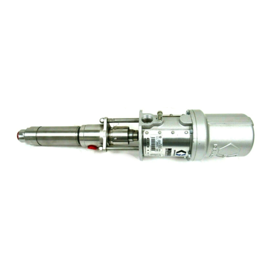
Model 224342 Shown
308116V
EN
0195
Advertisement
Table of Contents

Related Manuals for Graco 224342 A Series


Summary of Contents for Graco 224342 A Series
- Page 1 Instructions Stainless Steel Pumps 308116V Severe-Duty, UHMWPE/PTFE or PTFE Packed For transferring or dispensing low viscosity sealants and adhesives. For professional use only. Important Safety Instructions Read all warnings and instructions in this manual before using the equipment. Save these instructions. Model 224342 Shown 0195...
-
Page 2: Table Of Contents
Repair ........13 Graco Standard Warranty....28 Disconnect the Displacement Pump . -
Page 3: Models
Models Models UHMWPE/PTFE Packed Pumps Model 224342, Series A ® 10:1 Ratio President Pump 1800 psi (13 MPa, 125 bar) Maximum Fluid Working Pressure 180 psi (1.3 MPa, 12.5 bar) Maximum Air Input Pressure Ex II 2 G Ex h IIC T3 Gb Model 224343, Series A ®... -
Page 4: Warnings
Warnings Warnings The following warnings are for the setup, use, grounding, maintenance, and repair of this equipment. The exclamation point symbol alerts you to a general warning and the hazard symbols refer to procedure-specific risks. When these symbols appear in the body of this manual or on warning labels, refer back to these Warnings. Product-specific hazard symbols and warnings not covered in this section may appear throughout the body of this manual where applicable. - Page 5 Warnings WARNING MOVING PARTS HAZARD Moving parts can pinch, cut or amputate fingers and other body parts. • Keep clear of moving parts. • Do not operate equipment with protective guards or covers removed. • Equipment can start without warning. Before checking, moving, or servicing equipment, follow the Pressure Relief Procedure and disconnect all power sources.
-
Page 6: Typical Installation
Typical Installation Typical Installation 0774A . 1: Typical Installation Key: Pump Fluid Drain Valve (required) Pump Runaway Valve Fluid Filter Air Line Lubricator Fluid Supply Hose Bleed--Type Master Air Valve (required, for pump) Spray Gun Pump Air Regulator Fluid Suction Hose Air Line Filter Wall Bracket Bleed--Type Master Air Valve (for accessories) -
Page 7: Installation
The Accessories shown on page 8 is only a guide for Object being sprayed: follow local code. selecting and installing system components and accessories. Contact your Graco distributor for Solvent pails used when flushing: follow local code. assistance in designing a system to suit your particular Use only conductive metal pails, placed on a grounded needs. -
Page 8: Accessories
Accessories Accessories Install the following accessories in the order shown in • Air line lubricator (C): provides automatic air Operation, page 9, using adapters as necessary. motor lubrication. • Pump air regulator (E): to control pump speed and Air and Fluid Hoses outlet pressure. -
Page 9: Operation
Operation Operation Pressure Relief Procedure Flush the Equipment Follow the Pressure Relief Procedure whenever you see this symbol. To avoid fire and explosion, always ground equipment and waste container. To avoid static sparking and injury from splashing, always flush at the lowest possible pressure. -
Page 10: Packing Nut
2. Connect a suction hose (N) to the pump fluid inlet. 3. Hold a metal part of the spray gun (M) firmly to the Keep the packing nut/wet-cup (2) filled with Graco side of a grounded metal pail and hold the trigger ™... -
Page 11: Shutdown And Care For The Pump
Operation Shutdown and Care for the Pump 1. Perform the Pressure Relief Procedure, page 9. 2. Stop the pump at the bottom of its stroke. NOTICE If the pump stops at the top of its stroke, then fluid may dry on the exposed displacement rod and damage the throat packings. -
Page 12: Troubleshooting
Troubleshooting Troubleshooting 1. Perform Pressure Relief Procedure, page 9, before checking or repairing the pump. 2. Check all possible problems and causes before disassembling pump. Problem Cause Solution Pump fails to operate. Restricted line or inadequate air supply. Clear; increase air supply. Insufficient air pressure;... -
Page 13: Repair
Repair Repair Disconnect the Displacement Connect the Displacement Pump Pump 1. Perform Flush the Equipment procedure, page 9. 1. Lubricate the o-ring (110) and check that it is in Stop the pump at the bottom of its stroke. place on the displacement rod (13). 2. - Page 14 Repair 0194 Lubricate. Model 224342: Torque to 20--30 ft-lb (27--41 Nm). Models 224343, 902147, 247147, 261630: Torque to 10--15 ft-lb (14--20 Nm). Apply sealant, as required 308116V...
-
Page 15: Disassemble The Displacement Pump
Repair Disassemble the Displacement 10. Inspect the polished surfaces of the displacement rod (13) and cylinder (8) for scratches, scoring or Pump other damage, which can cause premature packing wear and leaking. To check, run a finger over the NOTE: When disassembling the pump, lay out removed surface or hold the part up to the light at an angle. - Page 16 Repair 8. Place the flats of the displacement rod (13) in a 10. Install the ball (4*), guide (9), o-ring (12), and ball vise. Apply sealant and screw the piston assembly stop pin (6*) in the intake valve housing (15). onto the displacement rod.
- Page 17 Repair Detail A: Throat Packings 24* or 5* 24* or 5* See Detail A NOTE: Lips of v-packings must face down. Detail B: Piston Packings See Detail B 20* or 23* 20* or 23* NOTE: Lips of u-packings must face up. 0191C 308116V...
-
Page 18: Parts
Parts Parts Model 224342 10:1 Ratio President Pump Ref. Part Description Qty. 224341 DISPLACEMENT PUMP ASSY. See pages 18--19 for parts 102021 NUT, lock; 3/8--16; stainless steel 166237 ROD, tie; stainless steel; 3.5 in. (89 mm) shoulder to shoulder 207352 AIR MOTOR See 306982 for parts 110‡... -
Page 19: Models 261630, 224343 (Shown)
Parts Models 261630, 224343 (shown) 5:1 Ratio Monark Pump Ref. Part Description Qty. 224341 DISPLACEMENT PUMP ASSY. for Model 224343 only; See pages 18--19 for parts 254999 DISPLACEMENT PUMP ASSY. for Model 261630 only; See pages 18--19 for parts 102021 NUT, lock; 3/8--16; stainless steel 24B189 KIT, tie rod 205997 AIR MOTOR See 307043 for parts... -
Page 20: Models 247147, 902147 (Shown)
Parts Models 247147, 902147 (shown) 5:1 Ratio Monark Pump Ref. Part Description Qty. 15G976 DISPLACEMENT PUMP ASSY. See pages 20--21 for parts 102021 NUT, lock; 3/8--16; sst 24B189 KIT, tie rod 205997 AIR MOTOR See 307043 for parts 110‡ 156082 SEAL, o-ring; nitrile rubber 111‡... -
Page 21: Model 254999, 224341 (Shown)
Parts Model 254999, 224341 (shown) Severe-Duty, UHMWPE/PTFE Packed Stainless Steel Displacement Pump ‡ 4* (224341 only)) 33 (254999 only) ‡ (Model 224341 only) (Model 224341 only) 0190C 308116V... - Page 22 Parts Model 254999, 224341, Severe-Duty, Ref. Part Description Qty. UHMWPE/PTFE Packed Stainless Steel 176635 V-PACKING, piston; PTFE Displacement Pump 176637 PIN, ball stop, piston; stainless steel Ref. Part Description Qty. 176638 V-PACKING, piston; UHMWPE 205999 HOUSING, outlet; stainless steel 176639 V-PACKING, throat; UHMWPE 186995 PACKING NUT/WET-CUP;...
-
Page 23: Model 15G976
Parts Model 15G976 Severe-Duty, PTFE Packed Stainless Steel Displacement Pump ‡ ‡ 0190C 308116V... - Page 24 Parts Model 15G976 Severe-Duty, PTFE Packed Ref. Part Description Qty. Stainless Steel Displacement Pump 186988 GLAND, throat, female; stainless steel Ref. Part Description Qty. 186992 HOUSING, valve, intake; 205999 HOUSING, outlet; stainless steel 186995 PACKING NUT/WET-CUP; stainless steel 176634 WASHER, piston; stainless steel stainless steel 176635 V-PACKING, piston;...
-
Page 25: Performance Charts
Performance Charts Performance Charts 10:1 President Key: cycles per min Fluid Outlet Pressure - Black Curves 1800 1800 scfm Air Consumption - Gray Curves 2.55 m³/min 180 psi (1.3 MPa, 12.5 bar) air pressure 1600 100 psi (0.7 MPa, 7 bar) air pressure 2.24 70 psi (0.5 MPa, 4.9 bar) air pressure 1400... -
Page 26: Dimensions
Performance Charts Dimensions Mounting Hole Layout Model 224342 Shown 4.38 in. (111.3 mm) 0.28 in. (7.1 mm) DIA. Diameter 2.5 in. 5.0 in. (64 mm) (127 mm) 1/2 npt(f) AIR INLET 1/2 npt(f) FLUID OUTLET 3/4 npt(f) FLUID INTAKE Pump Model 28.38 in. -
Page 27: Technical Specifications
Technical Specifications Technical Specifications 10:1 President Stainless Steel Pump Metric Maximum fluid working pressure 1800 psi 12.5 MPa, 125 bar Maximum air input pressure 180 psi 1.3 MPa, 12.5 bar Pump cycles per 1 gallon (3.8 liters) 20 cycles Maximum recommended pump speed for 60 cycles/min continuous operation Maximum flow at continuous duty... -
Page 28: Graco Standard Warranty
With the exception of any special, extended, or limited warranty published by Graco, Graco will, for a period of twelve months from the date of sale, repair or replace any part of the equipment determined by Graco to be defective.