Table of Contents
Advertisement
Quick Links
Repair - Parts
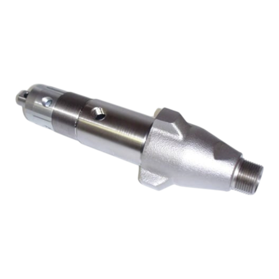
Displacement Pump
FOR USE WITH REACTOR
3500 psi (24.5 MPa, 245 bar) Maximum Working Pressure
Component A (ISO) Pumps with
wet-cup flush feature
Part No. 246830, Series A
2
2
0.396 in.
(2.55 cm
)
Part No. 246831, Series B
2
2
0.552 in.
(3.56 cm
)
Part No. 246832, Series A
2
2
0.743 in.
(4.79 cm
)
Part No. 262647, Series A
2
2
0.552 in.
(3.56 cm
)
Component B (Resin) Pumps
Part No. 245970, Series A
2
2
0.396 in.
(2.55 cm
)
Part No. 245971, Series B
2
2
0.552 in.
(3.56 cm
)
Part No. 245972, Series A
2
2
0.743 in.
(4.79 cm
)
Part No. 262648, Series A
2
2
0.552 in.
(3.56 cm
)
Important Safety Instructions
Read all warnings and instructions in this manual.
Save these instructions.
®
AIR AND ELECTRIC PROPORTIONERS
TI3733
309577K
EN
TI2663
Advertisement
Table of Contents

Related Manuals for Graco 246830


Summary of Contents for Graco 246830
- Page 1 FOR USE WITH REACTOR AIR AND ELECTRIC PROPORTIONERS 3500 psi (24.5 MPa, 245 bar) Maximum Working Pressure Component A (ISO) Pumps with wet-cup flush feature Part No. 246830, Series A 0.396 in. (2.55 cm Part No. 246831, Series B 0.552 in.
-
Page 2: Table Of Contents
Supply Wet-cups with Throat Seal Liquid ..7 Graco Information ......28 Cutaway Views . - Page 3 Misuse can cause serious injury or death. • For professional use only. • Use equipment only for its intended purpose. Call your Graco distributor for information. • Read manuals, warnings, tags, and labels before operating equipment. Follow instructions. • Check equipment daily. Repair or replace worn or damaged parts immediately.
- Page 4 Warning WARNING BURN HAZARD This equipment is used with heated fluid, which can cause equipment surfaces to become very hot. To avoid severe burns: • Do not touch hot fluid or equipment. • Allow equipment to cool completely before touching it. •...
-
Page 5: Pressure Relief Procedure
Pressure Relief Procedure Pressure Relief Procedure WARNING Read warnings, page 3. Relieve pressure in gun and perform gun shut- down procedure. See gun manual. Close gun fluid manifold valves A and B. TI2421A Shut off feed pumps and agitator, if used. Turn PRESSURE RELIEF/SPRAY valves (SA, SB) to PRESSURE RELIEF. -
Page 6: Tools Needed
Pick or long small screwdriver • Snap-ring pliers • 1/2 in. (13 mm) diameter plastic rod • 7/8 in. deep-well socket (246830 and 245970 only) • 1/2 in. (13 mm) x 2.5 in. (64 mm) bolt with washers and nut • Channel locks •... -
Page 7: Supply Wet-Cups With Throat Seal Liquid
Turn main power OFF before filling wet cup. Component A (ISO) Pump: Keep reservoir (R) 3/4 filled with Graco Throat Seal Liquid (TSL), TI3765a-1 Part No. 206995. Wet-cup piston (28) circulates TSL through packing nut/wet-cup (19), to carry away isocyanate film on displacement rod. -
Page 8: Cutaway Views
Cutaway Views Cutaway Views Component A (ISO) Pump 246830 246831 246832 262647 † † † † † † † † † † † † † † ‡*8 ‡*8 TI3734b TI3734C 309577K... - Page 9 Cutaway Views Component B (Resin) Pump 245970 245971 245972 262648 † † ‡*8 ‡*8 TI2668C TI2668b 309577K...
-
Page 10: Disassembly
Disassembly Disassembly WARNING Loosen star-shaped locknut (G) by hitting firmly with a non-sparking hammer. Unscrew pump far enough to expose retaining pin under plastic fin- ger guard. Push retaining spring up. Push pin Pump rod and connecting rod move during operation. out. - Page 11 Disassembly TI3765a-1 TI3765a-2 . 1. Disconnect Pump A . 2. Disconnect Pump B 309577K...
- Page 12 Disassembly Remove packing nut/wet-cup as follows: Loosen intake valve housing (5) with non-spark- ing hammer, then unscrew. Remove o-ring (15). Component A (ISO) Pumps: • Remove packing nut/wet-cup assembly. • Compress piston (28) into wet-cup (19), using a 1/2 in. (13 mm) x 2.5 in.
- Page 13 Disassembly Tap rod (1) with non-sparking hammer to drive it Unscrew piston (7) from rod (1). Remove ball out of cylinder (2). (16), u-cup (13), and bushing (14). TI2672B TI2672A 246831, 262647, 245971, Typical configuration and 262648 only Sleeve (4) may come out with rod. TI2666A TI2666B 246831, 262647, 245971,...
- Page 14 Disassembly 309577K...
-
Page 15: Reassembly
Reassembly Reassembly Coat all non-Loctited parts with Graco 217374 Install throat u-cup as follows: ISO Pump Oil before reassembly, to ease future disassembly. Install ball (16*) in rod (1). Center u-cup (13*) on Models 246831, 262647, 246832, rod (1). Lips of u-cup must face up. Use piston... - Page 16 Reassembly Insert bushing (17*). Press bushing in place to Component B (Resin) Pump: Install seat u-cup. felt washers (21*) into packing nut (19). Install retaining ring (22*). Install pack- ing nut handtight. TI2669B Assemble packing nut as follows: TI2701A Component A (ISO) Pump: Groove (H) in sleeve outer surface must be toward bottom.
- Page 17 1/4-3/8 in. (6-10 mm) of its greatest diameter is visible above packing nut (19). TI2687A Model Torque ft-lb (N•m) 246830 and 245970 65-75 (88-101) 246831, 262647, 245971, 75-85 (101-114) and 262648 246832 and 245972 145-155 (195-209)
- Page 18 Reassembly Tighten packing nut/wet-cup. Continue screwing pump into housing until fluid outlet (D) is aligned with steel tube and top threads are +/- 1/16 in. (2 mm) of bearing face (N). Do not overtighten packing nut/wet-cup. Throat u-cup (20) is not adjustable. Pump A: Wrap base of wet-cup (19) Tighten star-shaped locknut (G) by hitting firmly with a rag and tighten securely with...
- Page 19 Reassembly Flat side faces up. Lubricate threads with ISO oil or grease. Pump top threads must be nearly flush with bearing face (N). TI3765a-1 . 3. Reconnect Pump B 309577K...
- Page 20 Reassembly Steps 19-32 apply to pump A only. See F . 4. Apply thread sealant and screw barbed fitting into elbow (U). Torque to 10-15 ft-lb (14-20 Screw pump into bearing housing (M) until top N•m). Do not overtighten. threads are level with bearing face (N). Rotate pump to align pump outlet fitting to outlet tube.
- Page 21 Reassembly Flat side faces up. Lubricate threads with ISO oil or grease. Pump top threads must be nearly flush with bearing face (N). Finger guard (P) not used on Model E-30. TI3765a-2 . 4. Reconnect Pump A 309577K...
-
Page 22: Parts
Parts Parts Component A (ISO) Pumps, with wet-cup flush feature Part 246830, E-20 and E-XP1; includes items 1-7, 9-28 Part 246831, E-XP2; includes items 1-7, 9-22, 24-28 Part 262647, A-25; includes items 1-7, 9-22, 24-28 Part 246832, E-30; includes items 1-17, 19-22, 24-28 (shown) Used on 246832 only. - Page 23 Parts Part 246830, E-20 and E-XP1; includes items 1-7, 9-28 Part 246831, E-XP2; includes items 1-7, 9-22, 24-28 Part 262647, A-25; includes items 1-7, 9-22, 24-28 Part 246832, E-30; includes items 1-22, 24-28 (shown) Ref. Part Description Qty. Ref. Part Description Qty.
- Page 24 Parts Component B (Resin) Pumps Part 245970, E-20 and E-XP1; includes items 1-7, 9-23 Part 245971, E-XP2; includes items 1-7, 9-22 Part 262648, A-25; includes items 1-7, 9-22 Part 245972, E-30; includes items 1-22 (shown) NOTE: These pumps were also used on Component A (ISO) side of Reactors built before May 2003. Used on 245972 only.
- Page 25 Parts Part 245970, E-20 and E-XP1; includes items 1-7, 9-23 Part 245971, E-XP2; includes items 1-7, 9-22 Part 262648, A-25; includes items 1-7, 9-22 Part 245972, E-30; includes items 1-22 (shown) Ref. Part Description Qty. Ref. Part Description Qty. 105444 BALL, piston; sst; 0.3125 in. (8 mm) 240518 ROD, displacement;...
-
Page 26: Accessories
Accessories Accessories Wet-Cup Conversion Kits These kits convert 245970, 245971, 262648, or 245972 pumps to the wet-cup flush design. Refer to the follow- ing table to select the correct kit for your pump. Kits include instruction manual 309911. Pump Part No. Wet-Cup Conversion Kit 245970 248061, includes:... -
Page 27: Technical Data
(3.56 cm 246832 and 245972: 0.743 in. (4.79 cm Fluid inlet size 246830, 246831, 262647, 245970, 245971, and 262648: 3/4 npt(m) 246832 and 245972: 1 npsm(m) Fluid outlet size 246830 and 245970: 1/4 npt(f) 246831, 262647, 246832, 245971, 262648, and 245972: 3/8 npt(f) -
Page 28: Graco Standard Warranty
With the exception of any special, extended, or limited warranty published by Graco, Graco will, for a period of twelve months from the date of sale, repair or replace any part of the equipment determined by Graco to be defective.