Table of Contents
Advertisement
Available languages
Available languages
Quick Links
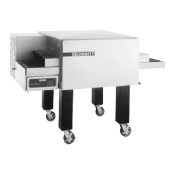
MT2136E/AB AND MT2136G/AB
CONVEYOR OVENS
INSTALLATION -- OPERATION -- MAINTENANCE
MT2136E/AB ET MT2136G/AB
FOURS À BANDE TRANSPORTEUSE
MANUEL D'INSTALLATION -- FONCTIONNEMENT -- ENTRETIEN
BLODGETT OVEN COMPANY
www.blodgettcorp.com
50 Lakeside Avenue, Box 586, Burlington, Vermont 05402 USA Telephone (800) 331-5842, (802) 860-3700 Fax: (802)864-0183
PN M6831 Rev D (6/01)
E 2000 --- G.S. Blodgett Corporation
Advertisement
Table of Contents

Related Manuals for Blodgett MT2136E/AB


Summary of Contents for Blodgett MT2136E/AB
- Page 1 FOURS À BANDE TRANSPORTEUSE MANUEL D’INSTALLATION -- FONCTIONNEMENT -- ENTRETIEN BLODGETT OVEN COMPANY www.blodgettcorp.com 50 Lakeside Avenue, Box 586, Burlington, Vermont 05402 USA Telephone (800) 331-5842, (802) 860-3700 Fax: (802)864-0183 PN M6831 Rev D (6/01) E 2000 --- G.S. Blodgett Corporation...
- Page 2 IMPORTANT WARNING: IMPROPER INSTALLATION, ADJUSTMENT, ALTERATION, SERVICE OR MAINTENANCE CAN CAUSE PROPERTY DAMAGE, INJURY OR DEATH. READ THE INSTALLATION, OPERATING AND MAINTENANCE INSTRUCTIONS THOROUGHLY BEFORE INSTALLING OR SERVICING THIS EQUIPMENT AVERTISSEMENT: UNE INSTALLATION, UN AJUSTEMENT, UNE ALTÉRATION, UN SERVICE OU UN ENTRETIEN NON CONFORME AUX NORMES PEUT CAUSER DES DOMMAGES À...
- Page 3 THE REPUTATION YOU CAN COUNT ON UNE RÉPUTATION SUR LAQUELLE VOUS POUVEZ COMPTER For over a century and a half, The Blodgett Oven Company has been building ovens and nothing but ovens. We’ve set the industry’s quality standard for all kinds of ovens for every foodservice operation regardless of size, application or budget.
- Page 4 Model/Modèl: Your Service Agency’s Address: Adresse de votre agence de service: Serial Number/Numéro de série: Your oven was installed by/ Installateur de votre four: Your oven’s installation was checked by/ Contrôleur de l’installation de votre four:...
-
Page 5: Table Of Contents
Table of Contents/Table des Matières Introduction Introduction Oven Description and Specifications ..Description et Spécifications du Four ..Oven Components ....Éléments du Four . -
Page 6: Introduction
The result is a high quality product, cooked at a lower temperature in a shorter amount of time. Conveyor Blodgett conveyor ovens represent the latest ad- Nozzle vancement in energy efficiency, reliability, and ease of operation. Heat normally lost, is recircu-... -
Page 7: Oven Components
Introduction Oven Components Conveyor Belt --- stainless steel chain link (con- Baking Chamber --- products pass through the veyor) belt that carries product through the oven. baking chamber on the conveyor belt for cooking. Conveyor Belt Master Links --- allow easy remov- Nozzles --- distribute heated air to bottom of the al of the conveyor belt for maintenance and clean- baking chamber. -
Page 8: Installation
Installation Delivery and Inspection All Blodgett ovens are shipped in containers to The Blodgett Oven Company cannot assume prevent damage. Upon delivery of your new oven: responsibility for loss or damage suffered in transit. The carrier assumed full responsibility Inspect the shipping container for external dam- for delivery in good order when the shipment age. -
Page 9: Oven Location And Ventilation
If you do not have a local dis- liquids and solvents. tributor, please call the Blodgett Oven Company at Do not place the oven on a curb base or seal to 0011-802-860-3700. -
Page 10: Oven Assembly
Installation Oven Assembly OVEN SUPPORTS AND CASTERS Triple Stacked Units 1. Rest the bottom oven on its back. Single and Double Stacked Units 2. Insert the caster stem through the square 1. Bolt the supports to the oven with 3/8-16 hex washer and into the threaded hole in the bot- head bolts. -
Page 11: Conveyor Belt Support
Installation Oven Assembly CONVEYOR BELT SUPPORT 2. Install the drive chain around the drive motor and the sprocket on the conveyor support. NOTE: Conveyor belt support is shipped installed Push the support back to tighten the chain. on some units. 1. -
Page 12: Conveyor Belt
Installation Oven Assembly CONVEYOR BELT To thread the conveyor belt 1. Start from the right hand side of the oven, low- NOTE: Conveyor belt is shipped installed on er level first. Unroll the belt as shown in some units. Figure 8, otherwise the belt will be upside Be sure to install the belt from left to right. - Page 13 Installation Oven Assembly 4. Install inner master links. See Figure 10 and 5. Install the outer master links. See Figure 12 Figure 11. and Figure 13 NOTE: The extra piece of wire belt can be used to make additional master links if the original links are lost or damaged.
-
Page 14: Conveyor Tunnel Extensions
Installation Oven Assembly CONVEYOR TUNNEL EXTENSIONS CRUMB PANS 1. Install the two conveyor tunnel extensions on 1. Install the crumb pans under each end of the each end of the oven. conveyor. Figure 16 Figure 14 REMOTE COMPUTER CONTROL 1. Drill the mounting holes for the cooking com- CONVEYOR BELT TENSIONER puter support base. -
Page 15: Utility Connections
If you do not have a local dis- required, and have complied with all requirements tributor, please call the Blodgett Oven Company at of state or local authorities having jurisdiction. 0011-802-860-3700. -
Page 16: Gas Connection
Installation Gas Connection GAS PIPING Maximum Capacity of Iron Pipe in Cubic Feet of Natural Gas Per Hour A properly sized gas supply system is essential for (Pressure drop of 0.5 Inch W.C.) maximum oven performance. Piping should be sized to provide a supply of gas sufficient to meet Pipe Nominal Size, Inches the maximum demand of all appliances on the line... - Page 17 Installation Gas Connection PRESSURE REGULATION AND TESTING gas and 13” W.C. (3.2 kPa) for Propane gas. The minimum gas supply pressure to MT2136/AB series ovens are rated at 55,000 BTU/ the oven is 4.5” W.C. (1.1 kPa) for natural Hr. (16 kW/Hr.). Australian ovens are rated at 52.1 gas and 11.0”...
- Page 18 If you have any questions regarding the prop- the studs of the wall. er installation and/or operation of your Blodgett oven, please contact your local distributor. If you WARNING!! do not have a local distributor, please call the Blodgett Oven Company at 0011-802-860-3700.
-
Page 19: Electrical Connection
220-240VAC, 3 wire service consisting of L1, neu- tral and ground. Use 90_C wire and size to Nation- THE BLODGETT OVEN COMPANY CANNOT AS- al Electric or local codes. SUME RESPONSIBILITY FOR LOSS OR DAMAGE SUFFERED AS A RESULT OF IMPROPER INSTAL- LATION. -
Page 20: Operation
They are the key to the General safety tips: successful operation of your Blodgett conveyor oven. DO NOT use tools to turn off the gas control. If the gas cannot be turned off manually do not try SAFETY TIPS to repair it. -
Page 21: Cooking Computer
Operation Cooking Computer CONTROL DESCRIPTION PROGRAMMING 1. DIGITAL DISPLAY --- displays the time, tem- Programming the Cook Time: perature and controller related information. 1. Press the PROGRAM/ENTER key (8). 2. OVEN ON/OFF --- controls power to the oven. 2. Press the TIME key (7). The display reads SET 3. - Page 22 Operation Cooking Computer OPERATION DISPLAY INFORMATION To turn the oven on: WAIT LOW --- the present oven temperature is lower than the set point temperature. When the 1. Turn the manual gas valve to ON. (Gas models oven reaches the set point temperature the dis- only) play changes to READY.
-
Page 23: Oven Adjustments For Cooking
Most often, the ideal oven settings can be dialed sults from your Blodgett conveyor oven. Use the in without making any changes to the airplate. The following guidelines to adjust the belt time and oven configuration should not be modified unless oven temperature of your unit. -
Page 24: Maintenance
Maintenance Cleaning WARNING!! Always disconnect the power supply be- fore cleaning or servicing the oven. WARNING!! If the oven needs to be moved, the gas must be turned off and disconnected from the unit before removing the restraint. Re- connect the restraint after the oven has been returned to its original location. - Page 25 Maintenance Cleaning 6. Loosen the screws at the top corners of the 9. Remove the crumb trays. side access panel. Lower the access panel. See Figure 24. Figure 27 10. Clean the oven interior with an appropriate Figure 24 oven cleaner safe for aluminum. 11.
- Page 26 If maintenance is required contact your local ser- the unit before removing the restraint. Re- vice company, a factory representative or the connect the restraint after the oven has Blodgett Oven company. been returned to its original location.
-
Page 27: Control Box Component Locations
Maintenance Control Box Component Locations MT2136G/AB Cooling Fan NOTE: Fan may run at any time. Burner Blower Head Module Control Burner Plate Blower Assembly Assembly Drive Chain Combination Pilot valve regulator Figure 28... - Page 28 Maintenance Control Box Component Locations MT2136E/AB Cooling Fan Contactor Heating Heating Elements Element Drive Chain Conveyor Motor Motor Contactor Figure 29...
-
Page 29: Troubleshooting Guide
*Denotes remedy is a difficult operation and should be performed by qualified personnel only. It is recommended, however, that All repairs and/or adjustments be done by your local Blodgett service agency and not by the owner/operator. Blodgett cannot as- sume responsibility for damage as a result of servicing done by unqualified personnel. - Page 30 *Denotes remedy is a difficult operation and should be performed by qualified personnel only. It is recommended, however, that All repairs and/or adjustments be done by your local Blodgett service agency and not by the owner/operator. Blodgett cannot as- sume responsibility for damage as a result of servicing done by unqualified personnel.
- Page 31 MT2136/AB Fours à Bande Transporteuse Manuel D’Installation --- Fonctionnement --- Entretien...
-
Page 32: Introduction
Fours à Bande Transporteuse la chambre de cuisson, d’importantes économies d’énergie peuvent être réalisées en même temps Figure 1 que d’excellents résultats de cuisson. SPÉCIFICATIONS MT2136G/AB MT2136E/AB Largeur de la bande 53 cm 53 cm Longueur de la zone 91 cm 91 cm... -
Page 33: Éléments Du Four
Introduction Éléments du Four Bande transporteuse --- bande (transporteuse) Chaîne d’entraînement --- connecte le pignon du articulée en acier inoxydable qui transporte les moteur d’entra”nement au pignon de support de produits dans le four. la bande transporteuse du côté de l’entraînement. Maillons de liaison de la bande transporteuse Chambre de cuisson du four --- pour cuire, les --- facilitent l’enlèvement de la bande transpor-... -
Page 34: Installation
Installation Livraison et Inspection Tous les fours sont expédiés en conteneurs. A la La Blodgett Oven Co., n’est pas responsable réception de votre four Blodgett vous devez: des dégâts subis pendant le transport. Le transporteur est seul responsable de la livrai- Vérifier que les emballages ne sont pas abimés. -
Page 35: Implantation Et Aération Du Four
Maintenez la zone du four libre et dégagée de vous avez des questions portant sur l’installation tous matériaux combustibles tels que le papier, et/ou l’utilisation adéquate de votre four Blodgett, le carton, ainsi que les liquides et solvants in- veuillez contacter votre distributeur local. Si aucun flammables. -
Page 36: Montage Du Four
Installation Montage du Four LES SUPPORTS DU FOUR ET LES ROULETTES Unités simples et superposées double Unités superposées triple 1. Poser le four du bas sur le dos. 1. Boulonnez les supports du four à celui-ci au moyen de boulons de 3/8-16 à tête plate. 2. -
Page 37: Support De Bande Transporteuse
Installation Montage du Four SUPPORT DE BANDE TRANSPORTEUSE 2. Installez la chaîne d’entraînement autour du moteur d’entraînement, puis autour du pig- NOTE: Sur certaines unités le support de la bande non du support de bande transporteuse. transporteuse est livré installé. Poussez le bande transporteuse en arrière 1. -
Page 38: La Bande Transporteuse Métallique
Installation Montage du Four LA BANDE TRANSPORTEUSE MÉTALLIQUE Pour installer la bande transporteuse 1. Insérez la bande transporteuse métallique en NOTE: Sur certaines unités le support de la bande partant du côté droit du four, en commençant transporteuse est livré installé. par le bas. - Page 39 Installation Montage du Four 4. Installez les liaisons principales internes. Re- 5. Installez les liaisons principales externes. Re- portez-vous aux Figure 10 et Figure 11. portez-vous aux Figure 12 et Figure 13 NOTE: Le morceau supplémentaire de bande métallique peut servir à confectionner des liaisons principales supplémentaires en À...
-
Page 40: Extensions Des Tunnels Du Convoyeur
Installation Montage du Four EXTENSIONS DES TUNNELS DU CONVOYEUR PLATEAUX POUR MIETTES 1. Installer les deux extensions des tunnels du 1. Installez des plateaux pour miettes sous cha- convoyeur à chaque extrémité du four. que extrémité de la bande transporteuse. Figure 16 Figure 14 L’ORDINATEUR DE CUISSON DÉTACHÉ... -
Page 41: Branchements De Service
à l’autre. Si vous avez des questions portant sur l’installation Le personnel qualifié pour l’installation doit avoir et/ou l’utilisation adéquate de votre four Blodgett, de l’expérience dans ce genre de travail, connaître veuillez contacter votre distributeur local. Si aucun toutes les précautions à... -
Page 42: Branchement De Gaz
Installation Branchement de Gaz CONDUIT DE GAZ Capacité maximum du tuyau métallique en pieds cubiques de gaz naturel à l’heure. Un système d’alimentation en gaz de bon calibre (chute de pression de 13 mm (0,5 po) est essentiel pour obtenir le meilleur rendement à... - Page 43 Installation Branchement de Gaz RÉGLAGE ET TEST DE PRESSION pour le gaz naturel et 13” W.C. pour le pro- pane. La pression minimum à la colonne Chaque section du four MT2136/AB opère à ré- d’eau de l’alimentation en gaz est 4.5” gime nominal de 55,000 BTU/heure (16 kw).
- Page 44 à l’autre. Si vous avez des questions portant sur l’installation AVERTISSEMENT!! et/ou l’utilisation adéquate de votre four Blodgett, veuillez contacter votre distributeur local. Si aucun Si la retenue est déconnectée, quelqu’en distributeur local n’est situé dans votre localité, soit la raison, elle doit être reconnectée...
-
Page 45: Raccordement Électrique
Installations aux États-Unis et au Canada que est conforme aux spécifications de tension, d’intensité et de phase indiquées sur la plaque Les fours MT2136E/AB sont disponibles en 1F ou signalétique. 3F (en option). Les modèles monophasés néces- sitent un service électrique de 90 amp., 60 Hz, Un schéma de câblage, à... - Page 46 MT2136G/AB 220-240 Four Alimentation 208-240 Alimentation Four Installations des appareils exportés et l’Australie Installations aux États-Unis et au Canada MT2136E/AB 208-240 Alimentation Four 208-240 Four Alimentation Installations aux États-Unis et au Canada --- Installations aux États-Unis et au Canada ---...
-
Page 47: Utilisation
Prenez le temps de lire attentivement les instruc- d’urgence comme interrupteur de marche/ar- tions qui suivent. Vous y trouverez la clé du succès ret! du four à transportbande Blodgett. Conseils généraux de sécurité : CONSEILS DE SÉCURITÉ NE PAS utiliser d’outil pour fermer les comman- des du gaz. -
Page 48: L'ordinateur De Cuisson
Utilisation L’Ordinateur de Cuisson IDENTIFICATION DES COMMANDES LA PROCÉDÉ PROGRAMMER 1. AFFICHAGE - Indique la durée et la tempéra- Pour programmer l’heure de cuisson: ture, ainsi que d’autres informations relatives 1. Appuyer sur la touche PROG ENTER (8). au fonctionnement du four. 2. - Page 49 Utilisation L’Ordinateur de Cuisson UTILISATION AUTRES MESSAGES DE L’AFFICHEUR Pour allumer le four WAIT LOW --- la température du four est inférieure à celle programmée. Quand le four at- 1. Tourner la vanne de gaz sur MARCHE. teindra la température programmée l’afficheur in- (Modèles à...
- Page 50 à con- La plaque de circulation d’air, située au-dessus de voyeur Blodgett. Utilisez les lignes directrices qui la chambre de cuisson, comporte des trous qui suivent pour ajuster le temps de passage de la peuvent être couverts par des plaques de blo-...
-
Page 51: Entretien
Entretien Nettoyage AVERTISSEMENT!! Débranchez le four de la prise de courant avant son nettoyage ou son entretien. AVERTISSEMENT!! Si le four doit être plus écarté du mur, l’ali- mentation en gaz doit être coupée et la canalisation débranchée du four avant d’enlever la chaîne. - Page 52 Entretien Nettoyage 6. Desserrer les vis aux coins supérieurs du pan- 9. Retirer les plateaux. neau d’accès latéral. Baisser le panneau d’accès. Voir Figure 24. Figure 27 10. Nettoyer l’intérieur du four avec un produit de Figure 24 nettoyage tout usage ou avec un produit de nettoyage de four sans danger pour l’alumi- 7.
- Page 53 Entretien Nettoyage Tous les 12 mois: AVERTISSEMENT!! Un technicien d’entretien agréé par l’usine doit: Débranchez le four de la prise de courant 1. Ouvrir le panneau de commande et nettoyer avant son nettoyage ou son entretien. l’intérieur de celui-ci. 2. Vérifier et resserrer toutes les connexions AVERTISSEMENT!! électriques.
-
Page 54: Emplacements Des Composants Du Boîtier De Commande
Entretien Emplacements des Composants du Boîtier de Commande MT2136G/AB Ventilateurs de refroidissement NOTE: Peut marcher n’importe quand. Module tête de soufflante de brûleur Assemblage Ensemble de de soufflante la plaque de de brûleur contrôle Chaîne d’entraînement Ensemble soupape pilote détendeur Figure 28... - Page 55 Entretien Emplacements des Composants du Boîtier de Commande MT2136E/AB Ventilateurs de refroidissement Éléments Élément de de chauffage chauffage du contacteur Chaîne d’entraînement Moteur de la bande transporteuse Contacteur du moteur Figure 29...
-
Page 56: Guide De Détection Des Pannes
TOUT réglage et/ou TOUTE réparation à un agent commercial ou représentant local Blodgett. Blodgett ne saura être tenu responsable d’un dommage résultant d’une répara- tion ou d’un service d’entretien effectué par un personnel non qualifié. - Page 57 TOUT réglage et/ou TOUTE réparation à un agent commercial ou représentant local Blodgett. Blodgett ne saura être tenu responsable d’un dommage résultant d’une répara- tion ou d’un service d’entretien effectué par un personnel non qualifié.
- Page 58 INSERT WIRING DIAGRAM HERE PLACER SCHÉMA DE CÂBLAGE...