Table of Contents
Advertisement
Quick Links
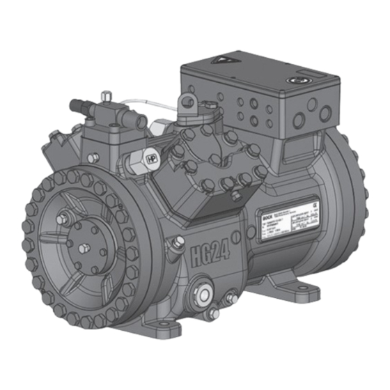
Reciprocating Compressor
BOCK
UL-HGX
®
Operating guide
UL-HGX24/55 ML(P) 6 CO
UL-HGX24/70 ML(P) 7 CO
UL-HGX24/90 ML(P) 8 CO
UL-HGX24/110 ML(P) 10 CO
Translation of the original instructions
2
4 CO
T
UL-HGX24/55 S(P) 7 CO
2
T
UL-HGX24/70 S(P) 9 CO
2
T
UL-HGX24/90 S(P) 12 CO
2
T UL-HGX24/110 S(P) 15 CO
2
T
2
T
UL-HGX24/55 SH(P) 7 CO
2
T
UL-HGX24/70 SH(P) 9 CO
2
T
UL-HGX24/90 SH(P) 12 CO
2
T UL-HGX24/110 SH(P) 15 CO
2
AQ450437934291en-US0301
T
2
T
2
T
2
T
2
Advertisement
Table of Contents

Related Manuals for Danfoss BOCK UL-HGX24 CO2 T Series


Summary of Contents for Danfoss BOCK UL-HGX24 CO2 T Series
- Page 1 Reciprocating Compressor 4 CO BOCK UL-HGX ® Operating guide UL-HGX24/55 ML(P) 6 CO UL-HGX24/55 S(P) 7 CO UL-HGX24/55 SH(P) 7 CO UL-HGX24/70 ML(P) 7 CO UL-HGX24/70 S(P) 9 CO UL-HGX24/70 SH(P) 9 CO UL-HGX24/90 ML(P) 8 CO UL-HGX24/90 S(P) 12 CO UL-HGX24/90 SH(P) 12 CO UL-HGX24/110 ML(P) 10 CO T UL-HGX24/110 S(P) 15 CO...
-
Page 2: Table Of Contents
1.4 Qualifications required of personnel..................5 Product description....................... 6 2.1 Short description........................6 2.2 Name plate..........................7 2.3 Type key..........................7 2.4 Type key compressors with LSPM Motor (Line Start Permanent Magnet)......8 © Danfoss | Climate Solutions | 2023.09 2 | AQ450437934291en-US0301... - Page 3 7.3 Spare parts recommendation / accessories................27 7.4 Lubricants / oil........................27 7.5 Decommissioning........................27 Technical data....................... 28 Dimensions and connections..................32 Declaration of incorporation..................34 UL-Certificate of Compliance..................36 © Danfoss | Climate Solutions | 2023.09 AQ450437934291en-US0301 | 3...
-
Page 4: Safety
140°F (60°C) on the pressure side or below 32°F (0°C) on the suction side can be reached. • Avoid contact with refrigerant under any circumstances. Contact with refrigerant can lead to severe burns and skin irritations. © Danfoss | Climate Solutions | 2023.09 4 | AQ450437934291en-US0301... -
Page 5: Intended Use
• As well as professions with comparable training, which enable personnel to assemble, install, maintain and repair refrigeration and air-conditioning systems. • Personnel must be capable of assessing the work to be carried out and recognizing any potential dangers. © Danfoss | Climate Solutions | 2023.09 AQ450437934291en-US0301 | 5... -
Page 6: Product Description
Oil pump Oil sight glass Fig. 1 Discharge shut-off valve (accessories) Terminal box Cylinder cover Suction shut-off valve (accessories) Fig. 2 Dimension and connection values can be found in chapter 9 © Danfoss | Climate Solutions | 2023.09 6 | AQ450437934291en-US0301... -
Page 7: Name Plate
ML - Normal cooling and deep freezing at low and medium evaporation temperatures - For frequency regulation and extended limits of application SH - For high evaporating temperatures eg. heat pumps, different oil charge © Danfoss | Climate Solutions | 2023.09 AQ450437934291en-US0301 | 7... -
Page 8: Type Key Compressors With Lspm Motor (Line Start Permanent Magnet)
The oil level must be in the visible part of the sight glass; 0,6 Ltr. / Oil level damage to the compressor 21 fl.oz min. is possible if overfilled or Fig. 4 underfilled! © Danfoss | Climate Solutions | 2023.09 8 | AQ450437934291en-US0301... -
Page 9: Limits Of Application
- A minimum running time of 3 min. steady-state condition (continuous operation) must be achieved. Avoid continuous operation in limit range. Max. permissible operating pressure (LP/HP) : 100/150 bar (1450/2176 psig) LP = Low pressure HP = High pressure © Danfoss | Climate Solutions | 2023.09 AQ450437934291en-US0301 | 9... -
Page 10: Compressor Assembly
Do not use in a corrosive, dusty, damp atmosphere or a com- bustible environment. Setup on an even surface or frame with sufficient load-bearing capacity. Single compressor preferably on vibration damper. Compound connection basically rigid. © Danfoss | Climate Solutions | 2023.09 10 | AQ450437934291en-US0301... -
Page 11: Connecting The Pipelines - Solder System
After assembly, it is necessary to check the collar. The gasket must not be damaged. At least 80 % of the cutting face has to be covered. After check-up, screw on and tighten again as described above. © Danfoss | Climate Solutions | 2023.09 AQ450437934291en-US0301 | 11... -
Page 12: Pipes
4.6 Flange shut-off valves (HP/LP) Risk of injury. The compressor must be depressurized through connections A1 and B1 before commencing any work and prior to connecting to the refrigerant system. Fig. 7 Fig. 8 © Danfoss | Climate Solutions | 2023.09 12 | AQ450437934291en-US0301... -
Page 13: Laying Suction And Pressure Lines
Before opening or closing the shut-off valve, release the valve spindle seal by approx. of a turn counter-clockwise. After activating the shut-off valve, re-tighten the adjustable valve spindle seal clockwise. Tighten Release Valve spindle seal Fig. 11 Fig. 10 © Danfoss | Climate Solutions | 2023.09 AQ450437934291en-US0301 | 13... -
Page 14: Operating Mode Of The Lockable Service Connections
For systems with long pipes and higher degree of contamination, a filter on the suction-side is recommended. The filter has to be be renewed depending on the degree of contamina- tion (reduced pressure loss). © Danfoss | Climate Solutions | 2023.09 14 | AQ450437934291en-US0301... -
Page 15: Electrical Connection
Adjust the overload protection device so that it must be actuated within 2 hours at 1.2 times the maximum working current. For compressors with LSPM motor, a faster responding overload protection device is recommended. © Danfoss | Climate Solutions | 2023.09 AQ450437934291en-US0301 | 15... -
Page 16: Connection Of The Driving Motor
5| Electrical connection 5.2 Connection of the driving motor The compressor is designed with a motor for star-delta circuits. Designation on the name plate ∆ / Y © Danfoss | Climate Solutions | 2023.09 16 | AQ450437934291en-US0301... - Page 17 The connection examples shown refer to the standard version. In the case 96027-11.06-DGbF of special voltages, the instructions affixed to the terminal box apply. Only direct start is possible with LSPM Motor. © Danfoss | Climate Solutions | 2023.09 AQ450437934291en-US0301 | 17...
-
Page 18: Circuit Diagram For Direct Start 230 V Δ / 400 V Y
Cold conductor (PTC sensor) motor winding Thermal protection thermostat (PTC sensor) Load circuit safety switches Control power circuit fuse High pressure safety monitor Safety chain (high/low pressure monitoring ) Release switch (thermostat/pressostat) © Danfoss | Climate Solutions | 2023.09 18 | AQ450437934291en-US0301... - Page 19 L1.1 L2.1 L3.1 L1.2 P> Θ Θ Main switch Control voltage switch Compressor motor Compressor contactor INT69 G Electronic trigger unit INT69 G Oil sump heater © Danfoss | Climate Solutions | 2023.09 AQ450437934291en-US0301 | 19...
-
Page 20: Electronic Trigger Unit Int69 G
5.6 Function test of the trigger unit INT69 G Before commissioning, after troubleshooting or making changes to the control power circuit, check the functionality of the trigger unit. Perform this check using a continuity tester or gauge. © Danfoss | Climate Solutions | 2023.09 20 | AQ450437934291en-US0301... -
Page 21: Oil Sump Heater
For start-up and low speed operation, a voltage boost of 10-20 V is recommended to slightly reduce the motor current and compensate for voltage drops through the compressor supply line (and filtering devices, if present). © Danfoss | Climate Solutions | 2023.09 AQ450437934291en-US0301 | 21... -
Page 22: Commissioning
Only dry test gases may be used for the leak test, e.g. nitrogen N2 min. 4.6 (= purity 99.996 % or higher). © Danfoss | Climate Solutions | 2023.09 22 | AQ450437934291en-US0301... -
Page 23: Evacuation
Avoid overfilling the machine with refrigerant! Do not charge liquid refrigerant into the suction-side on the compressor. Do not mix additives with the oil and refrigerant. © Danfoss | Climate Solutions | 2023.09 AQ450437934291en-US0301 | 23... -
Page 24: Start-Up
The pressure reduction for the pressure switches can occur either at the suction and pressure lines between the shut-off valve and compressor or at the non-lockable connections for the shut-off valves (connections A and B, see Chapter 9). © Danfoss | Climate Solutions | 2023.09 24 | AQ450437934291en-US0301... -
Page 25: Pressure Relief Valves
EN 378-2 or appropriate safety standards. Failure to observe can result in risk of injury from CO streaming out of the two pressure relief valves! streaming Fig. 17 © Danfoss | Climate Solutions | 2023.09 AQ450437934291en-US0301 | 25... -
Page 26: Avoiding Slugging
CO is produced which blocks the outlet and could hinder the streaming out of CO . Otherwise, there is the danger that pressure can be built up again. © Danfoss | Climate Solutions | 2023.09 26 | AQ450437934291en-US0301... -
Page 27: Work To Be Carried Out
For this reason the suction side (LP) and the high pressure side (HP) of the compressor have to be secured by decompression valves. © Danfoss | Climate Solutions | 2023.09 AQ450437934291en-US0301 | 27... -
Page 28: Technical Data
220-240 V ∆ / 380-420 V Y - 3 - 50 Hz Voltage 265-290 V ∆ / 440-480 V Y - 3 - 60 Hz Displacement (1450 / 1740 rpm) No. of cylinders Type UL-HGX24/ © Danfoss | Climate Solutions | 2023.09 28 | AQ450437934291en-US0301... - Page 29 8 | Technical data © Danfoss | Climate Solutions | 2023.09 AQ450437934291en-US0301 | 29...
- Page 30 220-240 V ∆ / 380-420 V Y - 3 - 50 Hz Voltage 265-290 V ∆ / 440-480 V Y - 3 - 60 Hz Displacement (1500 / 1800 rpm) No. of cylinders Type UL-HGX24/ © Danfoss | Climate Solutions | 2023.09 30 | AQ450437934291en-US0301...
- Page 31 8 | Technical data © Danfoss | Climate Solutions | 2023.09 AQ450437934291en-US0301 | 31...
-
Page 32: Dimensions And Connections
Mitteilung seines Inhalts sind ver- (Korrosionsschutz, Verpackung für sicheren © Danfoss | Climate Solutions | 2023.09 32 | AQ450437934291en-US0301 prohibited. Offenders will be held liable for the soweit nicht ausdrücklich gestattet. Zuwider- Transport). - Page 33 Decompression valve HP M24x1.5 Decompression valve LP M22x1.5 7 / 16 “ UNF Connection for Schrader valve, suction side 7 / 16 “ UNF Connection for Schrader valve, discharge side © Danfoss | Climate Solutions | 2023.09 AQ450437934291en-US0301 | 33...
-
Page 34: Declaration Of Incorporation
Bock GmbH Authorized person for compiling and handing Alexander Layh over technical documentation: Benzstraße 7 72636 Frickenhausen, Germany Frickenhausen, 04th of January 2021 i. A. Alexander Layh, Global Head of R&D © Danfoss | Climate Solutions | 2023.09 34 | AQ450437934291en-US0301... - Page 35 Bock GmbH Authorized person for compiling and handing Alexander Layh over technical documentation: Benzstraße 7 72636 Frickenhausen, Germany Frickenhausen, 14th of October 2022 i. A. Alexander Layh, Global Head of R&D © Danfoss | Climate Solutions | 2023.09 AQ450437934291en-US0301 | 35...
-
Page 36: Ul-Certificate Of Compliance
11 | UL-Certificate of Compliance Dear customer, the Certificate of Compliance can be downloaded by the following QR-Code: https://vap.bock.de/stationaryapplication/Data/ DocumentationFiles/COC CO2 trans.pdf © Danfoss | Climate Solutions | 2023.09 36 | AQ450437934291en-US0301... - Page 37 © Danfoss | Climate Solutions | 2023.09 AQ450437934291en-US0301 | 37...
- Page 38 © Danfoss | Climate Solutions | 2023.09 38 | AQ450437934291en-US0301...