Table of Contents
Advertisement
Quick Links
Reciprocating Compressor
UL-HGX 44 e/UL-HGX 5 6e
®
BOCK
Operating guide
UL-HGX44e/475 ML 9
UL-HGX44e/475 S 12
UL-HGX44e/565 ML 12
UL-HGX44e/565 S 15
UL-HGX44e/665 ML 14
UL-HGX44e/665 S 20
UL-HGX44e/770 ML 15
UL-HGX44e/770 S 22
Translation of the original instructions
UL-HGX56e/850 ML 18
UL-HGX56e/850 S 25
UL-HGX56e/995 ML 23
UL-HGX56e/995 S 30
UL-HGX56e/1155 ML 28
UL-HGX56e/1155 S 35
AQ450440081306en-US0201
Advertisement
Table of Contents

Related Manuals for Danfoss BOCK UL-HGX44e


Summary of Contents for Danfoss BOCK UL-HGX44e
- Page 1 Reciprocating Compressor UL-HGX 44 e/UL-HGX 5 6e ® BOCK Operating guide UL-HGX44e/475 ML 9 UL-HGX56e/850 ML 18 UL-HGX44e/475 S 12 UL-HGX56e/850 S 25 UL-HGX44e/565 ML 12 UL-HGX56e/995 ML 23 UL-HGX44e/565 S 15 UL-HGX56e/995 S 30 UL-HGX44e/665 ML 14 UL-HGX56e/1155 ML 28 UL-HGX44e/665 S 20 UL-HGX56e/1155 S 35 UL-HGX44e/770 ML 15...
-
Page 2: Table Of Contents
Short description ....................... 6 Name plate (example) ......................7 Type key (example) ......................7 Areas of application ......................8 Refrigerants ........................8 Oil charge .......................... 8 Limits of application ......................9 2 | AQ450440081306en-US0201 © Danfoss | Climate Solutions | 2023.07... - Page 3 Lubricants / oils ....................... 27 Decommissioning ......................27 Accessories ........................28 Capacity regulator......................28 Technical data........................ 30 Dimensions and connections ..................32 Declaration of incorporation ..................34 UL-Certificate of Compliance..................36 AQ450440081306en-US0201 | 3 © Danfoss | Climate Solutions | 2023.07...
-
Page 4: Safety
60°C (140°F) on the discharge side or below 0°C (32°F) on the suction side can be reached. - Contact with refrigerant must be avoided. Contact with refrigerant can cause severe burns and skin damage. 4 | AQ450440081306en-US0201 © Danfoss | Climate Solutions | 2023.07... -
Page 5: Intended Use
As well as professions with comparable training that enables personnel to assemble, install, maintain and repair refrigeration and air-conditioning systems. Personnel must be capable of assessing the work to be carried out and recognizing any potential dangers. AQ450440081306en-US0201 | 5 © Danfoss | Climate Solutions | 2023.07... -
Page 6: Product Description
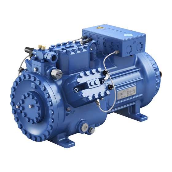
Name plate Oil sight glass Fig. 1 UL-HGX44e Discharge shut-off valve Suction shut-off valve Drive section Motor section Fig. 2 UL-HGX56e Dimension and connection values can be found in Chapter 9 6 | AQ450440081306en-US0201 © Danfoss | Climate Solutions | 2023.07... -
Page 7: Name Plate (Example)
Identification UL compressor HG - Hermetic Gas-Cooled (suction gas-cooled) ¹ X - Ester oil charge ² S - More powerful motor ML - Motor for normal cooling and deep freezing AQ450440081306en-US0201 | 7 © Danfoss | Climate Solutions | 2023.07... -
Page 8: Areas Of Application
The oil level must be in the Max. visible part of the sight glass; 1.9 ltr Oil level damage to the compressor is 67 fl.ozl possible if overfilled or under- Min. Fig. 4 filled! 8 | AQ450440081306en-US0201 © Danfoss | Climate Solutions | 2023.07... -
Page 9: Limits Of Application
Prevent the ingress of air at all costs! Maximum admissible operating pressure (LP/HP) LP = Low pressure 19/28 bar (276/406 psig) HP = High pressure AQ450440081306en-US0201 | 9 © Danfoss | Climate Solutions | 2023.07... -
Page 10: Compressor Assembly
Single compressor preferably on vibration damper. Duplex and parallel circuits always rigid. Sun protection: If the compressor is set up outdoors, it has to be protected from direct sunlight. 10 | AQ450440081306en-US0201 © Danfoss | Climate Solutions | 2023.07... -
Page 11: Pipe Connections
Improperly installed pipes can cause cracks and tears, the result being a loss of refrigerant. Proper layout of the suction and discharge lines directly after the compressor is integral to the system’s smooth running and vibration behavior. AQ450440081306en-US0201 | 11 © Danfoss | Climate Solutions | 2023.07... -
Page 12: Operating The Shut-Off Valves
Before opening or closing the shut-off valve, release the valve spindle seal by approx. ¼ of a turn counter-clockwise. After activating the shut-off valve, re-tighten the adjustable valve spindle seal clockwise. Tighten Release Valve spindle seal Fig. 7 Fig. 8 12 | AQ450440081306en-US0201 © Danfoss | Climate Solutions | 2023.07... -
Page 13: Operating Mode Of The Lockable Service Connections
Moisture in the refrigeration circuit can lead to crystal and hydrate formation. For this reason, we recommend using a filter drier and a sight glass with a moisture indicator. AQ450440081306en-US0201 | 13 © Danfoss | Climate Solutions | 2023.07... -
Page 14: Electrical Connection
50% of that for a direct start. A mechanical unloaded start with bypass solenoid valve is not required. 14 | AQ450440081306en-US0201 © Danfoss | Climate Solutions | 2023.07... - Page 15 After the motor starts up via partial winding 1, partial winding 2 must be switched on after a maximum delay of one second. Failure to comply can adversely affect the service life of the motor. AQ450440081306en-US0201 | 15 © Danfoss | Climate Solutions | 2023.07...
-
Page 16: Basic Circuit Diagramm For Part Winding Start With Standard Motor
Release switch (thermostat) Bearb. bauknecht DELTA-P II Oil differential pressure sensor DELTA-P II (accessorie) Gepr. 26.11.2020 Οnderung Datum Name Norm Urspr. Ers. f. Ers. d. Oil sump heater Compressor motor 16 | AQ450440081306en-US0201 © Danfoss | Climate Solutions | 2023.07... - Page 17 Electronic trigger unit INT69 G Delay relay for contactor switchover Main switch PW INT69 HG44/66 Mains contactor (part winding 1) Mains contactor (part winding 2) BOCK COMPRESSORS Control voltage switch AQ450440081306en-US0201 | 17 © Danfoss | Climate Solutions | 2023.07...
-
Page 18: Special Motor: Design For Direct Or Star-Delta Start
5.5 Special motor: design for direct or star-delta start A mechanical unloaded start with bypass solenoid valve is required for the star-delta start. Designation on the name plate ∆ / Y 18 | AQ450440081306en-US0201 © Danfoss | Climate Solutions | 2023.07... - Page 19 ∆ ∆ ∆ Star-delta start-up is only possible for 230 V power supply. Example: 230 V ∆ ∆ ∆ ∆ 400 V Y Direct start Star-delta start Direct start only AQ450440081306en-US0201 | 19 © Danfoss | Climate Solutions | 2023.07...
-
Page 20: Basic Circuit Diagramm For Star-Delta Start With Special Motor
Release switch (thermostat) Datum 20.02.2009 Bearb. bauknecht DELTA PII Oil differential pressure sensor DELTA-P II (accessorie) Gepr. 03.11.2020 Oil sump heater Οnderung Datum Name Norm Urspr. Ers. f. Ers. d. Compressor motor 20 | AQ450440081306en-US0201 © Danfoss | Climate Solutions | 2023.07... - Page 21 Control power circuit fuse INT69 G Electronic trigger unit INT69 G Delay relay for contactor switchover Main switch Mains contactor D/S INT69 HG44/66 neu Δ-contactor BOCK COMPRESSORS Y-contactor Control voltage switch AQ450440081306en-US0201 | 21 © Danfoss | Climate Solutions | 2023.07...
-
Page 22: Electronic Trigger Unit Int69 G
This would destroy N 43 43 11 X2 1 the trigger unit INT69 G and PTC Θ Θ Θ sensors. Steuerstrom- Control circuit Steuerstrom- kreis kreis Θ Fig. 13 Terminal box 22 | AQ450440081306en-US0201 © Danfoss | Climate Solutions | 2023.07... -
Page 23: Function Test Of The Trigger Unit Int69 G
The ability of the fuses to switch off must be greater than or equal to the maximum assumable short- circuit current at the installation location. AQ450440081306en-US0201 | 23 © Danfoss | Climate Solutions | 2023.07... -
Page 24: Selection And Operation Of Compressors With Frequency Converters
The compressor has been tested in the factory for pressure integrity. If however the entire system is to be subjected to a pressure integrity test, this should be carried out in accordance with EN 378-2 or a corresponding safety standard without the inclusion of the compressor. 24 | AQ450440081306en-US0201 © Danfoss | Climate Solutions | 2023.07... -
Page 25: Leak Test
Do not pour liquid coolant through the suction line valve on the compressor. It is not permissible to mix additives with the oil and refrigerant. AQ450440081306en-US0201 | 25 © Danfoss | Climate Solutions | 2023.07... -
Page 26: Start-Up
3 hole connection diagramm for Mechanical oil level regulator 3-Loch-Anschlussbild für ESK, ESK, AC&R and CARLY AC&R und CARLY at the "O" connection 3 hole diagramm for TraxOil 3-Loch-Anschlussbild für TraxOil 26 | AQ450440081306en-US0201 © Danfoss | Climate Solutions | 2023.07... -
Page 27: Maintenance
When the compressor is depressurised, undo the fastening screws of the shut-off valves. Remove the compressor using an appropriate hoist. Dispose of the oil inside in accordance with the applicable national regulations. AQ450440081306en-US0201 | 27 © Danfoss | Climate Solutions | 2023.07... -
Page 28: Accessories
Attention! Compressor is under pressure! Depressurize the compressor first. Fig. 19 Delivery condition 2 (from the factory): Connect capacity regulator in terminal box or switch cabinet. 28 | AQ450440081306en-US0201 © Danfoss | Climate Solutions | 2023.07... - Page 29 Information about the use, operation, maintenance and servicing of the components is available in the printed literature or on the internet under www.bock.de. For the capacity regulator a step protection is optional available, Art-Nr. 81449. Fig. 20 AQ450440081306en-US0201 | 29 © Danfoss | Climate Solutions | 2023.07...
-
Page 30: Technical Data
440-480 V Y/YY - 3 - 60 Hz PW Voltage PW = Part Winding Winding ratio : 50 % / 50 % Displacement (1450 / 1740 rpm) No. of cylinders Type UL-HGX44e/ 30 | AQ450440081306en-US0201 © Danfoss | Climate Solutions | 2023.07... - Page 31 440-480 V Y/YY - 3 - 60 Hz PW Voltage PW = Part Winding Winding ratio : 50 % / 50 % Displacement (1450 / 1740 rpm) No. of cylinders Type UL-HGX56e/ AQ450440081306en-US0201 | 31 © Danfoss | Climate Solutions | 2023.07...
-
Page 32: Dimensions And Connections
M12 x 1.5 Connection oil level regulator 3 x M6 Connection oil pressure differential sensor M20x1.5 Connection oil temperature sensor 8 “ NPTF Connection for refrigerant injection 8 “ NPTF 32 | AQ450440081306en-US0201 © Danfoss | Climate Solutions | 2023.07... - Page 33 M12 x 1.5 Connection oil level regulator 3 x M6 Connection oil pressure differential sensor M20x1.5 Connection oil temperature sensor 8 “ NPTF Connection for refrigerant injection “ NPTF 1 / 8 AQ450440081306en-US0201 | 33 © Danfoss | Climate Solutions | 2023.07...
-
Page 34: Declaration Of Incorporation
Bock GmbH Authorized person for compiling and handing Alexander Layh over technical documentation: Benzstraße 7 72636 Frickenhausen, Germany Frickenhausen, 04th of January 2021 i. A. Alexander Layh, Global Head of R&D 34 | AQ450440081306en-US0201 © Danfoss | Climate Solutions | 2023.07... - Page 35 Bock GmbH Authorized person for compiling and handing Alexander Layh over technical documentation: Benzstraße 7 72636 Frickenhausen, Germany Frickenhausen, 14th of October 2022 i. A. Alexander Layh, Global Head of R&D AQ450440081306en-US0201 | 35 © Danfoss | Climate Solutions | 2023.07...
-
Page 36: Ul-Certificate Of Compliance
12 | UL-Certificate of Compliance Dear customer, the Certificate of Compliance can be downloaded by the following QR-Code: https://vap.bock.de/stationaryapplication/Data/ DocumentationFiles/UL-Certificateofconformity.pdf 36 | AQ450440081306en-US0201 © Danfoss | Climate Solutions | 2023.07... - Page 37 AQ450440081306en-US0201 | 37 © Danfoss | Climate Solutions | 2023.07...
- Page 38 38 | AQ450440081306en-US0201 © Danfoss | Climate Solutions | 2023.07...