Table of Contents
Advertisement
Quick Links
®
BOCK
FK
Operating guide
FK20/120 N
FK20/145 N
FK20/120 K
FK20/145 K
FK20/120 TK
FK20/145 TK
FKX20/120 N
FKX20/145 N
FKX20/120 K
FKX20/145 K
FKX20/120 TK
FKX20/145 TK
Translation of the original instructions
2 0
FK20/170 N
FK20/170 K
FK20/170 TK
FKX20/170 N
FKX20/170 K
FKX20/170 TK
AQ451838788471en-000201
Advertisement
Table of Contents

Related Manuals for Danfoss BOCK FK20


Summary of Contents for Danfoss BOCK FK20
- Page 1 ® BOCK Operating guide FK20/120 N FK20/145 N FK20/170 N FK20/120 K FK20/145 K FK20/170 K FK20/120 TK FK20/145 TK FK20/170 TK FKX20/120 N FKX20/145 N FKX20/170 N FKX20/120 K FKX20/145 K FKX20/170 K FKX20/120 TK FKX20/145 TK FKX20/170 TK Translation of the original instructions AQ451838788471en-000201...
- Page 2 Such persons must read the safety advice and have understood it. Bock assumes no liability for any damage arising from non-compliance. 2 | AQ451838788471en-000201 © Danfoss | Climate Solutions | 2023.07...
-
Page 3: Table Of Contents
6.2 Work to be carried out 6.3 Recommended spare parts/accessories 6.4 Lubricants / Oils 6.5 Decommissioning 6.6 Valve plate, TK version Accessories 7.1 Thermal protection thermostat Technical Data Dimensions and Connections 10 Declaration of incorporation AQ451838788471en-000201 | 3 © Danfoss | Climate Solutions | 2023.07... -
Page 4: Safety
As well as professions with comparable training, which enables personnel to assemble, install, maintain and repair refrigeration and air-conditioning systems. Personnel must be capable of assessing the work to be carried out and recognising any potential dangers. 4 | AQ451838788471en-000201 © Danfoss | Climate Solutions | 2023.07... -
Page 5: Danger To Life And Limb In The Event Of Faults During Operation
Commissioning is permissible only if the compressor has been installed in accordance with these as- sembly instructions and the entire system into which it is integrated has been inspected and approved in accordance with legal regulations. AQ451838788471en-000201 | 5 © Danfoss | Climate Solutions | 2023.07... -
Page 6: Product Description
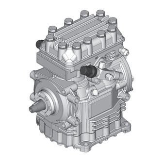
Discharge shut-off valve Shaft seal Shaft end Fig. 1 Valve plate Suction shut-off valve Oil pump Sight glass Fig. 2 Dimension and connection values can be found in Chapter 9 6 | AQ451838788471en-000201 © Danfoss | Climate Solutions | 2023.07... -
Page 7: Type Key
Swept volume Size Ester oil charging ² Series ¹ K - specially for air-conditioning N - specially for air-conditioning or normal cooling TK - specially for deep freezing X - Ester oil charging (HFC refrigerant, e.g. R134a, R407C) ² AQ451838788471en-000201 | 7 © Danfoss | Climate Solutions | 2023.07... -
Page 8: Areas Of Application
This can cause chemical reactions, a pressure rise in the condenser and an elevated compressed- gas temperature. Prevent the ingress of air at all costs! Max. permissible operating pressure (g) high-pressure side (HP): 28 bar 8 | AQ451838788471en-000201 © Danfoss | Climate Solutions | 2023.07... -
Page 9: Compressor Assembly
4.2 Maximum permissible inclination ATTENTION! Poor lubrication can damage the compressor. Respect the stated values. max. 30°, max. 2 minutes max. 15°, continuous operation Fig. 4 AQ451838788471en-000201 | 9 © Danfoss | Climate Solutions | 2023.07... -
Page 10: V-Belt Drive
The following description applies for an electromagnetic clutch secured to a shaft. To absorb the magnetic field of the electromagnetic clutch, the sliding ring lid has a snug fit Ø 38 h8 (see Fig. 6). To connect the magnetic field, remove the marked Allen head screws of the sliding ring lid (see Fig. 7). Slide the magnetic field to a snug-fit and fasten using the three M5 x 20 cheese head screws provided (Fig. 7). Screw torque = 9 Nm. Further assembly of the electromagnetic clutch according to the clutch manufacturer. Sliding ring lid Magnetic field Fig. 6 Fig. 7 Snug fit 10 | AQ451838788471en-000201 © Danfoss | Climate Solutions | 2023.07... -
Page 11: Pipe Connections
Before opening or closing the shut-off valve, release the valve spindle seal by approx. ¼ of a turn counter-clockwise. After activating the shut-off valve, re-tighten the adjustable valve spindle seal clockwise. Release Tighten Valve spindle seal Fig. 9 Fig. 10 AQ451838788471en-000201 | 11 © Danfoss | Climate Solutions | 2023.07... -
Page 12: Operating Mode Of The Lockable Service Connections
Connection 3 is provided for safety devices and is not lockable. After activating the spindle, generally fit the spindle protection cap again and tighten with 14-16 Nm. This serves as a second sealing feature during operation. 4.10 Suction pipe filter For systems with long pipes and higher degree of contamination, a filter on the suction-side is recommended. The filter has to be be renewed depending on the degree of contamination (reduced pressure loss). 12 | AQ451838788471en-000201 © Danfoss | Climate Solutions | 2023.07... -
Page 13: Commissioning
Evacuate the suction and discharge pressure sides using the vacuum pump. At the end of the evacuation process, the vacuum should be < 1.5 mbar when the pump is switched off. Repeat the process as often as is required. AQ451838788471en-000201 | 13 © Danfoss | Climate Solutions | 2023.07... -
Page 14: Refrigerant Charge
The complete refrigerant circuit must be correctly executed and clean inside. Heavy shocks and vibrations to the shaft as well as continuous cyclic operation are to be avoided. The sealing surfaces can stick together during prolonged downtimes (e.g. winter). Therefore, run the system every 4 weeks for 10 minutes. 14 | AQ451838788471en-000201 © Danfoss | Climate Solutions | 2023.07... -
Page 15: Notes On Replacing The Shaft Seal
The capacities of all components must be compatible (particularly evaporator and expansion valve). Suction gas superheating at the evaporator output should be at least 7 – 10 K (check setting of the expansion valve). The system must reach a state of equilibrium. Particularly in critical systems (e.g. several evaporator points), suitable measures, e.g. use of liquid traps, solenoid valve in the liquid line, etc. are recommended. AQ451838788471en-000201 | 15 © Danfoss | Climate Solutions | 2023.07... -
Page 16: Maintenance
The shaft seal must also be changed after 3 years. Regular inspections (at least annually): Checks to be carried out on oil level in the oil sight glass, oil fill level of the shaft seal in the oil drain hose, absence of leaks in the compressor, running noise, vibrations, pressures, temperatures, and functioning of auxiliary devices such as the capacity control. 16 | AQ451838788471en-000201 © Danfoss | Climate Solutions | 2023.07... -
Page 17: Recommended Spare Parts/Accessories
When the compressor is depressurised, undo the fastening screws of the shut-off valves. Remove the compressor using an appropriate hoist. Dispose of the oil inside in accordance with the valid national regulations. AQ451838788471en-000201 | 17 © Danfoss | Climate Solutions | 2023.07... -
Page 18: Valve Plate, Tk Version
2.5 A at 24 V DC Switch-off temperature : 145 °C ± 5 K Switch-on temperature : approx. 115 °C * Please note that the legacy BOCK code numbers are without 097B 18 | AQ451838788471en-000201 © Danfoss | Climate Solutions | 2023.07... -
Page 19: Technical Data
8| Technical data No. of cylinders AQ451838788471en-000201 | 19 © Danfoss | Climate Solutions | 2023.07... -
Page 20: Dimensions And Connections
±1 = Centre of gravity Dimensions in () = K Design Dimensions in mm Fig. 14 Shaft end View X 6xM5 0x26 A4x6,5 DIN6888 24,7 34,3 36,3 55,1 Fig. 15 Dimensions in mm 20 | AQ451838788471en-000201 © Danfoss | Climate Solutions | 2023.07... - Page 21 G 3 / 8 " 1) Opt. connection for oil sump heating Oil charge plug 4 " NPTF 1 1 / 8 " - 18 UNEF Sight glass = Only possible ex factory AQ451838788471en-000201 | 21 © Danfoss | Climate Solutions | 2023.07...
-
Page 22: Declaration Of Incorporation
Bock GmbH Authorized person for compiling and handing Alexander Layh over technical documentation: Benzstraße 7 72636 Frickenhausen, Germany Frickenhausen, 04th of January 2021 i. A. Alexander Layh, Global Head of R&D 22 | AQ451838788471en-000201 © Danfoss | Climate Solutions | 2023.07... - Page 23 Bock GmbH Authorized person for compiling and handing Alexander Layh over technical documentation: Benzstraße 7 72636 Frickenhausen, Germany Frickenhausen, 14th of October 2022 i. A. Alexander Layh, Global Head of R&D AQ451838788471en-000201 | 23 © Danfoss | Climate Solutions | 2023.07...
- Page 24 24 | AQ451838788471en-000201 © Danfoss | Climate Solutions | 2023.07...