Table of Contents
Advertisement
Quick Links
Advertisement
Table of Contents

Related Manuals for Danfoss BOCK HGX22e/125-4 A


Summary of Contents for Danfoss BOCK HGX22e/125-4 A
- Page 1 BOCK (P)(e) A ® Operating guide HGX22e/125-4 A HGX22e/125-4 S A HGX22e/160-4 A HGX22e/160-4 S A HGX22e/190-4 A HGX22e/190-4 S A HGX22P/125-4 A HGX22P/125-4 S A HGX22P/160-4 A HGX22P/160-4 S A HGX22P/190-4 A HGX22P/190-4 S A Translation of the original instructions AQ452755960718en-000201...
- Page 2 Observe the safety instructions contained in these instructions. These instructions must be passed onto the end customer along with the unit in which the compres- sor is installed. © Danfoss | Climate Solutions | 2023.06 2 | AQ452755960718en-000201...
-
Page 3: Table Of Contents
6.7 Avoiding slugging Maintenance 7.1 Preparation 7.2 Work to be carried out 7.3 Spare parts recommendation/accessories 7.4 Lubricants / oil 7.5 Decommissioning Technical data Dimensions and connections Declaration of incorporation © Danfoss | Climate Solutions | 2023.06 AQ452755960718en-000201 | 3... -
Page 4: Safety
As well as professions with comparable training, which enables personnel to assemble, install, maintain and repair refrigeration and air-conditioning systems. Personnel must be capable of assessing the work to be carried out and recognising any potential dangers. © Danfoss | Climate Solutions | 2023.06 4 | AQ452755960718en-000201... -
Page 5: General Safety Instructions
The compressors are intended for use in refrigeration systems in compliance with the limits of application. Only the refrigerant specified in these instructions may be used. Any other use of the compressor is prohibited! © Danfoss | Climate Solutions | 2023.06 AQ452755960718en-000201 | 5... -
Page 6: Product Description
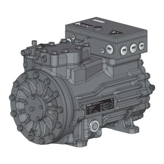
Oil sight glass Fig. 1 Cylinder cover Terminal box Valve plate Drive section Suction Motor section shut-off valve Fig. 2 Dimension and connection values can be found in Chapter 9 © Danfoss | Climate Solutions | 2023.06 6 | AQ452755960718en-000201... -
Page 7: Type Key
= e-series / P = Pluscom Numbers of cylinders Size Oil charge ² Series ¹ ¹ HG - Hermetic Gas-cooled (suction gas-cooled) ² X - Ester oil charge (HFC refrigerant, e.g. R134a, R404A/R507, R407C) ³ S - More powerful motor, e.g. for air-conditioning applications © Danfoss | Climate Solutions | 2023.06 AQ452755960718en-000201 | 7... -
Page 8: Areas Of Application
- Max. permissible current consumption must not be exceeded. At max. rotation speed therefore, the application limit can be reduced. - Use a thermal protection thermostat. - Do not operate an additional capacity controller. - Oil return at low frequency must be guaranteed. © Danfoss | Climate Solutions | 2023.06 8 | AQ452755960718en-000201... - Page 9 Prevent the ingress of air at all costs! LP = Low pressure Max. permissible operating pressure (LP/HP) HP = High pressure 19/28 bar © Danfoss | Climate Solutions | 2023.06 AQ452755960718en-000201 | 9...
-
Page 10: Compressor Assembly
Provide adequate clearance for maintenance work. Ensure adequate compressor ventilation. Fig. 7 Do not use in a dusty, damp atmosphere or a combustible environment. Fig. 8 Set up on an even surface or frame with sufficient load- bearing capacity. Fig. 9 © Danfoss | Climate Solutions | 2023.06 10 | AQ452755960718en-000201... -
Page 11: Maximum Permissible Inclination
The same applies for non-return valves. Fig. 11: Stepped internal diameters ATTENTION! Overheating can damage the valve. Remove the pipe supports from the valve for soldering. Solder them with protective gas to prevent oxidation products (scale). © Danfoss | Climate Solutions | 2023.06 AQ452755960718en-000201 | 11... -
Page 12: Pipes
¼ of a turn counter-clockwise. After activating the shut-off valve, re-tighten the adjustable valve spindle seal clockwise. Release Valve spindle seal Tighten Fig. similar Fig. similar Fig. 14 Fig. 13 © Danfoss | Climate Solutions | 2023.06 12 | AQ452755960718en-000201... -
Page 13: Operating Mode Of The Lockable Service Connections
For systems with long pipes and higher degree of contamination, a filter on the suction-side is recommended. The filter has to be be renewed depending on the degree of contamination (reduced pressure loss). Moisture in the refrigeration circuit can lead to crystal and hydrate formation. For this reason, we recommend using a filter drier and a sight glass with a moisture indicator. © Danfoss | Climate Solutions | 2023.06 AQ452755960718en-000201 | 13... -
Page 14: Electrical Connection
For motor protection use a current-dependent and time-delayed overload protection device for moni- toring all three phases. Set the overload protection device so that it must be actuated within 2 hours, if there is 1.2 times the max. working current. © Danfoss | Climate Solutions | 2023.06 14 | AQ452755960718en-000201... -
Page 15: Connection Of The Driving Motor
Star-delta start Direct start only L1 L2 L1 L2 L1 L2 L1 L2 INFO! The connection examples shown refer to the standard version. In the case of special voltages, the instructions affixed to the 96027-11.06-DGbF terminal box apply. L1 L2 96027-11.06-DGbF © Danfoss | Climate Solutions | 2023.06 AQ452755960718en-000201 | 15... - Page 16 Anschlußkasten Verdichter Compressor terminal box Fig. 17 Cold conductor (PTC sensor) motor winding Thermal protection thermostat (PTC sensor) Load circuit safety switches Control power circuit fuse High pressure safety monitor Safety chain (high/low pressure monitoring ) Release switch (thermostat) © Danfoss | Climate Solutions | 2023.06 16 | AQ452755960718en-000201...
- Page 17 L1.1 L2.1 L3.1 L1.2 P> Θ Θ Main switch Control voltage switch Compressor motor Compressor contactor INT69 G Electronic trigger unit INT69 G Oil sump heater © Danfoss | Climate Solutions | 2023.06 AQ452755960718en-000201 | 17...
-
Page 18: Electronic Trigger Unit Int69 G
This would destroy the trigger unit INT69 G and PTC sensors. N 43 43 11 X2 1 Θ Θ Θ Steuerstrom- Control circuit Steuerstrom- kreis kreis Θ PTC1 PTC2 Fig. 18 Terminal box © Danfoss | Climate Solutions | 2023.06 18 | AQ452755960718en-000201... -
Page 19: External Connection Int69 G
Reset after mains on 08.05.2020 11-14 Datum 04.12.2009 HG22e/34e HC Datum Name Norm Urspr. Ers. f. Ers. d. Bearb. bauknecht Gepr. 08.05.2020 Datum Name Norm Urspr. Ers. f. Ers. d. © Danfoss | Climate Solutions | 2023.06 AQ452755960718en-000201 | 19... -
Page 20: Commissioning
Evacuate the suction and high pressure sides using the vacuum pump. At the end of the evacuation process, the vacuum should be < 1.5 mbar when the pump is switched off. Repeat the process as often as is required. © Danfoss | Climate Solutions | 2023.06 20 | AQ452755960718en-000201... -
Page 21: Refrigerant Charge
Suction gas superheat at the compressor input should be min. 7 - 10 K. (check the setting of the expansion valve). The system must reach a state of equilibrium. Particularly in critical systems (e.g. several evaporator points), measures are recommended such as replacement of liquid traps, solenoid valve in the liquid line, etc. There should be no movement of refrigerant in the compressor while the system is at a standstill. © Danfoss | Climate Solutions | 2023.06 AQ452755960718en-000201 | 21... -
Page 22: Maintenance
7.3 Spare parts recommendation/accessories Available spare parts and accessories can be found on our compressor selection tool under vap.bock.de as well as at bockshop.bock.de. Only use genuine Bock spare parts! © Danfoss | Climate Solutions | 2023.06 22 | AQ452755960718en-000201... -
Page 23: Lubricants / Oil
When the compressor is depressurised, undo the fastening screws of the shut-off valves. Remove the compressor using an appropriate hoist. Dispose of the oil inside in accordance with the valid national regulations. © Danfoss | Climate Solutions | 2023.06 AQ452755960718en-000201 | 23... -
Page 24: Technical Data
Oil charge Weight 220-240 V ∆ / 380-420 V Y - 3 - 50 Hz 265-290 V ∆ / 440-480 V Y - 3 - 60 Hz No. of cylinders © Danfoss | Climate Solutions | 2023.06 24 | AQ452755960718en-000201... -
Page 25: Dimensions And Connections
Tol.-Ang. DIN ISO 2768-m Anschluß Saugseite, absperrbar Zoll über 0.5 Anschluß Saugseite Zoll ±0.1 ±0.2 ±0.3 ±0. Anschluß Saugseite Zoll Unbemaßte Radien: © Danfoss | Climate Solutions | 2023.06 AQ452755960718en-000201 | 25 Div. Änderungen (Betrifft Bl. 2+3) 7022,7090,7176,7181 21.11.07 Layh... -
Page 26: Declaration Of Incorporation
Bock GmbH Authorized person for compiling and handing Alexander Layh over technical documentation: Benzstraße 7 72636 Frickenhausen, Germany Frickenhausen, 04th of January 2021 i. A. Alexander Layh, Global Head of R&D © Danfoss | Climate Solutions | 2023.06 26 | AQ452755960718en-000201... - Page 27 Bock GmbH Authorized person for compiling and handing Alexander Layh over technical documentation: Benzstraße 7 72636 Frickenhausen, Germany Frickenhausen, 14th of October 2022 i. A. Alexander Layh, Global Head of R&D © Danfoss | Climate Solutions | 2023.06 AQ452755960718en-000201 | 27...
- Page 28 © Danfoss | Climate Solutions | 2023.06 28 | AQ452755960718en-000201...
- Page 29 © Danfoss | Climate Solutions | 2023.06 AQ452755960718en-000201 | 29...
- Page 30 © Danfoss | Climate Solutions | 2023.06 30 | AQ452755960718en-000201...