Table of Contents
Advertisement
Quick Links
Reciprocating Compressor
BOCK
UL-HGX
®
Operating guide
UL-HGX24e/55 ML 3 CO
UL-HGX24e/70 ML 4 CO
UL-HGX24e/90 ML 4 CO
UL-HGX24e/110 ML 5 CO
UL-HGX24e/130 ML 6 CO
UL-HGX24e/145 ML 7 CO
Translation of the original instructions
2
LT
UL-HGX24e/55 S 4 CO
2
LT
UL-HGX24e/70 S 5 CO
2
LT
UL-HGX24e/90 S 5 CO
2
LT
UL-HGX24e/110 S 7 CO
2
LT
UL-HGX24e/130 S 8 CO
2
LT
UL-HGX24e/145 S 9 CO
2
4 e CO
LT
2
LT
2
LT
2
LT
2
LT
2
LT
2
LT
2
AQ450435396289en-US0201
Advertisement
Table of Contents

Related Manuals for Danfoss BOCK UL-HGX24e CO2 LT


Summary of Contents for Danfoss BOCK UL-HGX24e CO2 LT
- Page 1 Reciprocating Compressor 4 e CO BOCK UL-HGX ® Operating guide UL-HGX24e/55 ML 3 CO UL-HGX24e/55 S 4 CO UL-HGX24e/70 ML 4 CO UL-HGX24e/70 S 5 CO UL-HGX24e/90 ML 4 CO UL-HGX24e/90 S 5 CO UL-HGX24e/110 ML 5 CO UL-HGX24e/110 S 7 CO UL-HGX24e/130 ML 6 CO UL-HGX24e/130 S 8 CO UL-HGX24e/145 ML 7 CO...
-
Page 2: Table Of Contents
Identification of safety instructions..................4 1.2 Qualifications required of personnel..................4 1.3 Safety instructions......................... 5 1.4 Intended use.......................... 5 Product description....................... 6 2.1 Short description........................6 2.2 Name plate..........................7 2.3 Type key..........................7 © Danfoss | Climate Solutions | 2023.07 2 | AQ450435396289en-US0201... - Page 3 7.2 Work to be carried out......................27 7.3 Spare parts recommendation / accessories................27 7.4 Lubricants..........................27 7.5 Decommissioning........................27 Technical data....................... 28 Dimensions and connections..................30 Declaration of incorporation..................32 11 UL-Certificate of Compliance..................34 © Danfoss | Climate Solutions | 2023.07 AQ450435396289en-US0201 | 3...
-
Page 4: Safety
140°F (60°C) on the pressure side or below 32°F (0°C) on the suction side can be reached. • Avoid contact with refrigerant under any circumstances. Contact with refrigerant can lead to severe burns and skin irritations. © Danfoss | Climate Solutions | 2023.07 4 | AQ450435396289en-US0201... -
Page 5: Qualifications Required Of Personnel
• As well as professions with comparable training, which enable personnel to assemble, install, maintain and repair refrigeration and air-conditioning systems. • Personnel must be capable of assessing the work to be carried out and recognizing any potential dangers. © Danfoss | Climate Solutions | 2023.07 AQ450435396289en-US0201 | 5... -
Page 6: Product Description
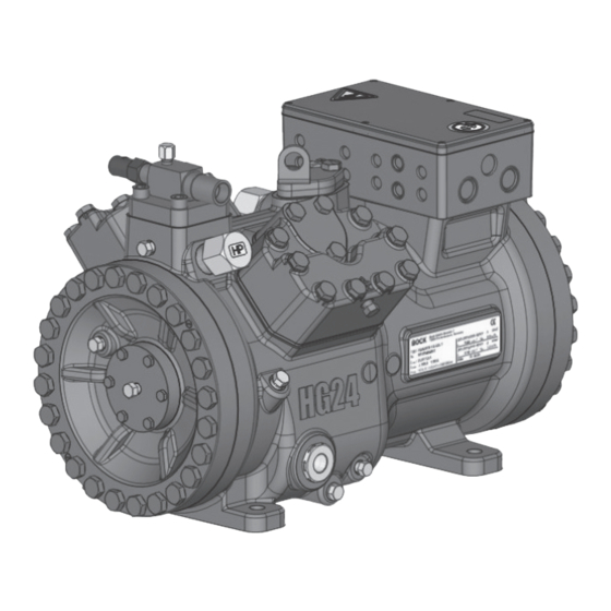
Oil sight glass Fig. 1 Discharge shut-off valve (accessories) Terminal box Cylinder cover Suction shut-off valve (accessories) Fig. 2 (includes accessories) Dimension and connection values can be found in chapter 9 © Danfoss | Climate Solutions | 2023.07 6 | AQ450435396289en-US0201... -
Page 7: Name Plate
HG - Hermetic Gas-Cooled (suction gas-cooled) ² - Ester oil charge ³ ML - Deep freezing at low and medium evaporation temperatures - For frequency regulation and extended limits of application © Danfoss | Climate Solutions | 2023.07 AQ450435396289en-US0201 | 7... -
Page 8: Areas Of Application
The oil level must be in the 21 fl.oz visible part of the sight glass; Oil level 0,6 Ltr. damage to the compressor min. is possible if overfilled or Fig. 4 underfilled! © Danfoss | Climate Solutions | 2023.07 8 | AQ450435396289en-US0201... -
Page 9: Limits Of Application
(continuous operation) must be achieved. Avoid continuous operation in limit range. For operation with frequency converter: - Frequency range 30 - 70 Hz. Max. permissible operating pressure (LP/HP) : 1450/1450 psig, 100/100 bar LP = Low pressure HP = High pressure © Danfoss | Climate Solutions | 2023.07 AQ450435396289en-US0201 | 9... -
Page 10: Compressor Assembly
Do not use in a corrosive, dusty, damp atmosphere or a com- bustible environment. Setup on an even surface or frame with sufficient load-bearing capacity. Single compressor preferably on vibration damper. Compound connection basically rigid. © Danfoss | Climate Solutions | 2023.07 10 | AQ450435396289en-US0201... -
Page 11: Connecting The Pipelines - Solder System
After assembly, it is necessary to check the collar. The gasket must not be damaged. At least 80 % of the cutting face has to be covered. After check-up, screw on and tighten again as described above. © Danfoss | Climate Solutions | 2023.07 AQ450435396289en-US0201 | 11... -
Page 12: Pipes
4.6 Flange shut-off valves (HP/LP) Risk of injury. The compressor must be depressurized through connections A1 and B1 before commencing any work and prior to connecting to the refrigerant system. Fig. 7 Fig. 8 © Danfoss | Climate Solutions | 2023.07 12 | AQ450435396289en-US0201... -
Page 13: Laying Suction And Pressure Lines
Before opening or closing the shut-off valve, release the valve spindle seal by approx. of a turn counter-clockwise. After activating the shut-off valve, re-tighten the adjustable valve spindle seal clockwise. Tighten Release Valve spindle seal Fig. 11 Fig. 10 © Danfoss | Climate Solutions | 2023.07 AQ450435396289en-US0201 | 13... -
Page 14: Operating Mode Of The Lockable Service Connections
For systems with long pipes and higher degree of contamination, a filter on the suction-side is recommended. The filter has to be be renewed depending on the degree of contamina- tion (reduced pressure loss). © Danfoss | Climate Solutions | 2023.07 14 | AQ450435396289en-US0201... -
Page 15: Electrical Connection
Adjust the overload protection device so that it must be actuated within 2 hours at 1.2 times the maximum working current. © Danfoss | Climate Solutions | 2023.07 AQ450435396289en-US0201 | 15... -
Page 16: Connection Of The Driving Motor
5| Electrical connection 5.2 Connection of the driving motor The compressor is designed with a motor for star-delta circuits. Designation on the name plate ∆ / Y © Danfoss | Climate Solutions | 2023.07 16 | AQ450435396289en-US0201... - Page 17 Insulators L1 L2 INFO The supplied insulators must be mounted according to the illustrations as shown. The connection examples shown refer to the standard version. In the case 96027-11.06-DGbF of special voltages, the instructions affixed to the terminal box apply. © Danfoss | Climate Solutions | 2023.07 AQ450435396289en-US0201 | 17...
-
Page 18: Circuit Diagram For Direct Start 280 V Δ / 460 V Y
Fig. 14 High pressure safety monitor Safety chain (high/low pressure monitoring ) Cold conductor (PTC sensor) motor winding Thermal protection thermostat (PTC sensor) Release switch (thermostat) Oil sump heater Compressor motor © Danfoss | Climate Solutions | 2023.07 18 | AQ450435396289en-US0201... - Page 19 L1.1 L2.1 L3.1 L1.2 P> Θ Θ FC1.1 Motor protection switch Control power circuit fuse INT69 G Electronic trigger unit INT69 G Main switch Mains contactor Control voltage switch © Danfoss | Climate Solutions | 2023.07 AQ450435396289en-US0201 | 19...
-
Page 20: Electronic Trigger Unit Int69 G
N 43 43 11 X2 1 This would destroy the trigger unit Θ Θ Θ INT69 G and PTC Control circuit Steuerstrom- Steuerstrom- sensors. kreis kreis Θ Fig. 15 Terminal box © Danfoss | Climate Solutions | 2023.07 20 | AQ450435396289en-US0201... -
Page 21: Functional Test Of The Electronic Trigger Unit Int69 G
The permissible frequency range can be found in the technical data. Rotational speed 0 - f-min f-min - f-max range Start-up time < 1 s ca. 4 s immediately Switch-off time f-min/f-max see chapter: Technical data: permissible frequency range © Danfoss | Climate Solutions | 2023.07 AQ450435396289en-US0201 | 21... -
Page 22: Commissioning
Only dry test gases may be used for the leak test, e.g. nitrogen N2 min. 4.6 (= purity 99.996 % or higher). © Danfoss | Climate Solutions | 2023.07 22 | AQ450435396289en-US0201... -
Page 23: Evacuation
A refrigerant supplement, which may become necessary after start-up, can be topped up in vapor form on the suction side. Avoid overfilling the machine with refrigerant! Do not charge liquid refrigerant into the suction-side on the compressor. Do not mix additives with the oil and refrigerant. © Danfoss | Climate Solutions | 2023.07 AQ450435396289en-US0201 | 23... -
Page 24: Start-Up
The pressure reduction for the pressure switches can occur either at the suction and pressure lines between the shut-off valve and compressor or at the non-lockable connections for the shut-off valves (connections A and B, see Chapter 9). © Danfoss | Climate Solutions | 2023.07 24 | AQ450435396289en-US0201... -
Page 25: Pressure Relief Valves
EN 378-2 or appropriate safety standards. Failure to observe can result in risk of injury from CO streaming out of the two decompression valves! streaming Fig. 17 © Danfoss | Climate Solutions | 2023.07 AQ450435396289en-US0201 | 25... -
Page 26: Avoiding Slugging
CO is produced which blocks the outlet and could hinder the streaming out of CO . Otherwise, there is the danger that pressure can be built up again. © Danfoss | Climate Solutions | 2023.07 26 | AQ450435396289en-US0201... -
Page 27: Work To Be Carried Out
For this reason the suction side (LP) and the high pressure side (HP) of the compressor have to be secured by decompression valves. © Danfoss | Climate Solutions | 2023.07 AQ450435396289en-US0201 | 27... -
Page 28: Technical Data
(rotor locked) Max. power consumption Max. operating current 265-290 V ∆ / 440-480 V Y - 3 - 60 Hz Voltage Displacement (1450 / 1740 rpm) No. of cylinders Type UL-HGX24e/ © Danfoss | Climate Solutions | 2023.07 28 | AQ450435396289en-US0201... - Page 29 8 | Technical data © Danfoss | Climate Solutions | 2023.07 AQ450435396289en-US0201 | 29...
-
Page 30: Dimensions And Connections
V. Polizzi C. Egeler handlungen verpflichten zu Schadenersatz. Alle 0c | Betrifft Blatt 4 Rechte für den Fall der Patent-, Gebrauchsmuster- © Danfoss | Climate Solutions | 2023.07 oder Geschmacksmustereintragung 30 | AQ450435396289en-US0201 vorbehalten. 0b | Betrifft Bl. 2-4 11430 08.06.21... - Page 31 2 x 1 1 / 8 “ - 18 UNEF Connection oil level regulator 1 / 8 “ NPTF Connection oil temperature sensor Decompression valve HD M22x1.5 Decompression valve HP M22x1.5 © Danfoss | Climate Solutions | 2023.07 AQ450435396289en-US0201 | 31...
-
Page 32: Declaration Of Incorporation
Bock GmbH Authorized person for compiling and handing Alexander Layh over technical documentation: Benzstraße 7 72636 Frickenhausen, Germany Frickenhausen, 04th of January 2021 i. A. Alexander Layh, Global Head of R&D © Danfoss | Climate Solutions | 2023.07 32 | AQ450435396289en-US0201... - Page 33 Bock GmbH Authorized person for compiling and handing Alexander Layh over technical documentation: Benzstraße 7 72636 Frickenhausen, Germany Frickenhausen, 14th of October 2022 i. A. Alexander Layh, Global Head of R&D © Danfoss | Climate Solutions | 2023.07 AQ450435396289en-US0201 | 33...
-
Page 34: Ul-Certificate Of Compliance
11 | UL-Certificate of Compliance Dear customer, the Certificate of Compliance can be downloaded by the following QR-Code: https://vap.bock.de/stationaryapplication/Data/ DocumentationFiles/COC CO2 trans.pdf © Danfoss | Climate Solutions | 2023.07 34 | AQ450435396289en-US0201... - Page 35 © Danfoss | Climate Solutions | 2023.07 AQ450435396289en-US0201 | 35...
- Page 36 © Danfoss | Climate Solutions | 2023.07 36 | AQ450435396289en-US0201...