Table of Contents
Advertisement
Quick Links
FK 5
®
BOCK
Operating guide
FK50/460 N
FK50/555 N
FK50/460 K
FK50/555 K
FKX50/460 N FKX50/555 N
FKX50/460 K
FKX50/555 K
FKX50/830 N FKX50/980 N
FKX50/830 K FKX50/980 K
FKX50/830 K1 FKX50/980 K1
Translation of the original instructions
0
FK50/660 N
FK50/775 N
FK50/660 K
FK50/775 K
FK50/660 K1
FK50/775 K1
FKX50/660 N FKX50/775 N
FKX50/660 K FKX50/775 K
FKX50/660 K1 FKX50/775 K1
FK50/830 N
FK50/980 N
FK50/830 K
FK50/980 K
FK50/830 K1
FK50/980 K1
AQ453354265896en-000201
Advertisement
Table of Contents

Related Manuals for Danfoss BOCK FK50


Summary of Contents for Danfoss BOCK FK50
- Page 1 FK 5 ® BOCK Operating guide FK50/460 N FK50/555 N FK50/660 N FK50/775 N FK50/830 N FK50/980 N FK50/460 K FK50/555 K FK50/660 K FK50/775 K FK50/830 K FK50/980 K FK50/660 K1 FK50/775 K1 FK50/830 K1 FK50/980 K1 FKX50/460 N FKX50/555 N FKX50/660 N FKX50/775 N FKX50/460 K FKX50/555 K...
- Page 2 Such persons must read the safety advice and have understood it. Bock assumes no liability for any damage arising from non-compliance. 2 | AQ453354265896en-000201 © Danfoss | Climate Solutions | 2023.07...
-
Page 3: Table Of Contents
6.4 Recommended spare parts 6.5 Integrated decompression valves 6.6 Lubricants / Oils 6.7 Decommissioning Accessories 7.1 Capacity regulator 7.2 Thermi protection thermostat Technical Data Dimensions and Connections 10 Declaration of incorporation AQ453354265896en-000201| 3 © Danfoss | Climate Solutions | 2023.07... -
Page 4: Safety
• If there is a sharp reduction in refrigerating capacity, switch the compressor off immediately. • Secure the compressor against being switched on again. • In such cases do not continue to operate the compressor under any circumstances. 4 | AQ453354265896en-000201 © Danfoss | Climate Solutions | 2023.07... -
Page 5: General Safety Instructions
Commissioning is permissible only if the compressor has been installed in accordance with these assembly instructions and the entire system into which it is integrated has been inspected and approved in accordance with legal regulations. AQ453354265896en-000201| 5 © Danfoss | Climate Solutions | 2023.07... -
Page 6: Product Description
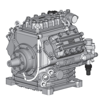
Oil sight glass Fig. 1 Cylinder cover Valve plate Suction shut-off valve Oil pump Oil sightglass Suction line valve Fig. 2 Dimension and connection values can be found in Chapter 9 6 | AQ453354265896en-000201 © Danfoss | Climate Solutions | 2023.07... -
Page 7: Type Key
2.3 Type key (example) 775 N Designs ¹ Swept volume Size Ester oil charging ² Series ¹ K - specially for air-conditioning N - specially for air-conditioning or normal cooling X - Ester oil charging (HFC refrigerant, e.g. R134a, R407C) ² AQ453354265896en-000201| 7 © Danfoss | Climate Solutions | 2023.07... -
Page 8: Areas Of Application
Prevent the ingress of air at all costs! Maximum admissible LP = Low pressure operating pressure (g) HP = High pressure (LP/HP) : 19/28 bar 8 | AQ453354265896en-000201 © Danfoss | Climate Solutions | 2023.07... -
Page 9: Compressor Assembly
4.2 Maximum permissible inclination ATTENTION Poor lubrication can damage the compressor. Respect the stated values. max. 30°, max. 2 minutes max. 15°, continuous operation Fig. 5 AQ453354265896en-000201| 9 © Danfoss | Climate Solutions | 2023.07... -
Page 10: V-Belt Drive
To absorb the magnetic field of the electromagnetic clutch, the front bearing flange has a snug fit 148 h8 (see Fig. 7). To connect the magnetic field, loosen the 4 cheese head screws M8 on the bearing flange (see Fig. 7). Slide the magnetic field to a snug fit and re-attach using the four cheese head screws M8 (Fig. 8). Screw torque = 37 Nm. Further assembly of the electromagnetic clutch according to the clutch manufacturer. Bearing flange, front Magnetic field 148 h8 Fig. 7 Fig. 8 10 | AQ453354265896en-000201 © Danfoss | Climate Solutions | 2023.07... -
Page 11: Pipe Connections
Before opening or closing the shut-off valve, release the valve spindle seal by approx. ¼ of a turn counter-clockwise. After activating the shut-off valve, re-tighten the adjustable valve spindle seal clockwise. Release Valve spindle seal Tighten Fig. 10 Fig. 11 AQ453354265896en-000201| 11 © Danfoss | Climate Solutions | 2023.07... -
Page 12: Suction Pipe Filter
Fig. 13 After activating the spindle, generally fit the spindle protection cap again and tighten with 14-16 Nm. This serves as a second sealing feature during operation. 4.10 Suction pipe filter For systems with long pipes and higher degree of contamination, a filter on the suction-side is recommended. The filter has to be be renewed depending on the degree of contamination (reduced pressure loss). 12 | AQ453354265896en-000201 © Danfoss | Climate Solutions | 2023.07... -
Page 13: Characteristics For K1 Special Housing F
11738 16.12.22 C. Polizzi A. Layh A. Layh 26.07.22 S. Büttner 11620 BOCK G Maß Dimension Passung / Clearance Änd.-Nr. / Mod-No. Datum / Date Bearb. / Edited Geprüft / Appr. AQ453354265896en-000201| 13 © Danfoss | Climate Solutions | 2023.07... -
Page 14: Preparations For Start-Up
Evacuate the suction and discharge pressure sides using the vacuum pump. At the end of the evacuation process, the vacuum should be < 1.5 mbar when the pump is switched off. Repeat the process as often as is required. 14 | AQ453354265896en-000201 © Danfoss | Climate Solutions | 2023.07... -
Page 15: Refrigerant Charge
0.05 ml per operating hour is therefore normal. This applies particularly during the run-in phase (200 - 300 h). T o trap and collect leaked oil, the FK50 is fitted with an inte- grated leak oil trapping device with oil reservoir (P.6, Fig. 1). AQ453354265896en-000201| 15 © Danfoss | Climate Solutions | 2023.07... -
Page 16: Avoiding Liquid Shocks
• Then after every 5,000 operating hours, at the latest however after 3 years. Also clean the oil filter. • An oil change is also necessary, if the oil is very cloudy and dark, or after repairs have been car- ried out on the compressor. 16 | AQ453354265896en-000201 © Danfoss | Climate Solutions | 2023.07... -
Page 17: Shaft Seal, Emptying The Oil Reservoir
• Thermal overload (operation outside the limits of application) • Frequent cycling • Long periods of stoppage • Material deposits / dirt from the system Due to these effects, the shaft seal can develop leaks, and it must then be replaced. AQ453354265896en-000201| 17 © Danfoss | Climate Solutions | 2023.07... -
Page 18: Recommended Spare Parts
When the compressor is depressurised, undo the fastening screws of the shut-off valves. Remove the compressor using an appropriate hoist. Dispose of the oil inside in accordance with the valid national regulations. 18 | AQ453354265896en-000201 © Danfoss | Climate Solutions | 2023.07... -
Page 19: Accessories
Item No.* Item No.* Special accessory 12 V 097B08703 097B08708 Special accessory 24 V 097B08704 097B08709 For a description, see technical information "Capacity regulation" (Item No. 09900) If the capacity regulator is factory-fitted, it is integrated into an extra, dedicated cylinder cover. For retrofits, it is supplied with the cylinder cover. The regulator closes one cylinder bank at a time (capacity regulation approx. 33 %). Two retrofit kits are required for a capacity regulation of approx. 66 %. * Please note that the legacy BOCK ref. numbers are without 097B AQ453354265896en-000201| 19 © Danfoss | Climate Solutions | 2023.07... -
Page 20: Thermi Protection Thermostat
2.5 A at 24 V DC Switch-off temperature : 145 °C ± 5 K Switch-on temperature : approx. 115 °C * Please note that the legacy BOCK ref. numbers are without 097B 20 | AQ453354265896en-000201 © Danfoss | Climate Solutions | 2023.07... -
Page 21: Technical Data
8| Technical data No. of cylinders AQ453354265896en-000201| 21 © Danfoss | Climate Solutions | 2023.07... -
Page 22: Dimensions And Connections
Änd.-Nr. / Mod-No. Datum / Date Bearb. / Edited Geprüft / Appr. ±0.1 ±0.2 ±0.3 ±0.5 ±0.8 22 | AQ453354265896en-000201 © Danfoss | Climate Solutions | 2023.07 Oberflächenbehandlung, Härte / Treatment Oberflächenangaben / Unbemaßte Radien / Undimensioned radii: Indication of surface texture... - Page 23 2 x 1 1 / 8 "- 18 UNEF Sight glass Connection thermal protection thermostat 8 " NPTF Oil strainer M22 x 1.5 Opt. connection for suction line valve 1) No connection available as standard. Available on request (Connection M22 x 1.5) AQ453354265896en-000201| 23 © Danfoss | Climate Solutions | 2023.07...
-
Page 24: Declaration Of Incorporation
Bock GmbH Authorized person for compiling and handing Alexander Layh over technical documentation: Benzstraße 7 72636 Frickenhausen, Germany Frickenhausen, 04th of January 2021 i. A. Alexander Layh, Global Head of R&D 24 | AQ453354265896en-000201 © Danfoss | Climate Solutions | 2023.07... - Page 25 Bock GmbH Authorized person for compiling and handing Alexander Layh over technical documentation: Benzstraße 7 72636 Frickenhausen, Germany Frickenhausen, 14th of October 2022 i. A. Alexander Layh, Global Head of R&D AQ453354265896en-000201| 25 © Danfoss | Climate Solutions | 2023.07...
- Page 26 26 | AQ453354265896en-000201 © Danfoss | Climate Solutions | 2023.07...