
Related Manuals for Endress+Hauser Stamolys CA71CR


Summary of Contents for Endress+Hauser Stamolys CA71CR
- Page 1 Operating Instructions Stamolys CA71CR Analyzer for Photometric Determination of Chromate BA358C/07/en/10.06 51512320 Valid as of: Software version 5.9...
- Page 2 → ä 36, → ä 58 Maintenance schedule → ä 36 Replacing consumables and wear parts → ä 42, → ä 54 Accessories Æ → ä 43 Troubleshooting → ä 45, → ä 54 Spare parts Æ → ä 48 Technical data Endress+Hauser...
-
Page 3: Table Of Contents
Stamolys CA71CR Table of contents Safety instructions ....4 Dilution module ......42 Additional accessories . -
Page 4: Safety Instructions
Safety instructions Stamolys CA71CR Safety instructions Designated use The analyzer is a compact photometric analytical system. It is designed for monitoring chromate content in industrial applications. CA71 is particularly suitable for the following applications: • Monitoring chromate in industrial sewage treatment plants •... -
Page 5: Notes On Safety Icons And Icons
Stamolys CA71CR Safety instructions Notes on safety icons and icons Warning! This symbol alerts you to hazards. They could cause serious injuries as well as damage to the instrument if ignored. Caution! " This symbol alerts you to possible faults which could arise from incorrect operation. They could cause damage to the instrument if ignored. -
Page 6: Identification
Identification Stamolys CA71CR Identification Device designation 2.1.1 Nameplate Compare the order code on the nameplate (on the analyzer) to the product structure and your order. You can read the following information from the nameplate: • Order code (device version) • Serial number •... -
Page 7: Scope Of Delivery
Stamolys CA71CR Identification Scope of delivery Note! Reagents must be ordered separately for version CA71XX-XXXXXX1. Inactive reagents form part of the scope of delivery for all other versions. They must be mixed before use. Please refer to the guidelines enclosed for this purpose. -
Page 8: Installation
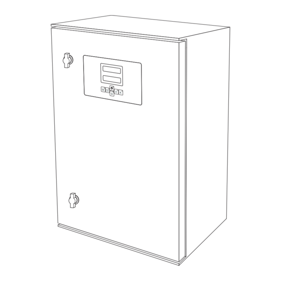
Installation Stamolys CA71CR Installation The analyzer at a glance a0006574 Fig. 2: Analyzer (cabinet version, without hoses) Reagent pump (P2), supply from canister Valve V2 Display Outlet for sample or reagent mixture Serial interface RS 232 Valve V1 Photometer cell... -
Page 9: Incoming Acceptance, Transport, Storage
Stamolys CA71CR Installation Incoming acceptance, transport, storage • Make sure the packaging is undamaged! Inform the supplier about damage to the packaging. Keep the damaged packaging until the matter has been settled. • Make sure the contents are undamaged! Inform the supplier about damage to the delivery contents. - Page 10 Installation Stamolys CA71CR Version with GFR housing 163 (6.42) 250 (9.84) 160 (6.30) 140 (5.51) 100(3.94) 330 (13.0) 60 (2.36) 7-11/ 0.28 - 0.43 (M 6) 200 (7.87) Ø 26 (1.02) 326 (12.8) Ø 16 (0.63) 360 (14.2) 436 (17.2) Ø...
- Page 11 Stamolys CA71CR Installation Note! For the reagents, you need an additional base at max. 35 cm (13.8 inch) under the pumps in the open version. The dimensions of the reagent bottles are as follows: 90 x 90 x 215 mm (3.54 x 3.54 x 8.46 inch).
-
Page 12: Installation Instructions
Installation Stamolys CA71CR Adjusting the level monitoring You have to adjust conductive level monitoring depending on whether you want to connect one, two or three analyzers to this single collecting vessel. Depending on the application, mount the right adjusting pin (→ å 8, → å 9, item 2) or do not use any adjusting pin. - Page 13 Stamolys CA71CR Installation a0006362 Fig. 11: Valves and valve hoses V1-2 Valves Outlet hose Channel switchover Hose, valve 2 at front, standard To sample pump Hose, valve 2 at rear, cleaner Connecting hose to valve 1, at rear Hose, valve 1 at front, sample Secure the hose boxes in the appropriate pump holders (→...
-
Page 14: Installation Examples
Installation Stamolys CA71CR Installation examples 3.5.1 CAT 430 or ultrafiltration provided by customer and two CA 71 units • Permeate can contain air bubbles (CAT430) or is free of bubbles (ultrafiltration provided by customer) • Distance between the analyzers as short as... -
Page 15: Wiring
Stamolys CA71CR Wiring Wiring Electrical connection Warning! • The electrical connection may only be established by an electrical technician. • The electrical technician must have read and understood these Operating Instructions and must follow the instructions they contain. • Before beginning the connection work, ensure that no voltage is applied to the cables. - Page 16 Wiring Stamolys CA71CR 4.1.2 Terminal assignment " Caution! The following diagram shows an example of the connection compartment sticker (→ å 16). The terminal assignment and cable colors can deviate from the actual assignment and colors! Only use the terminal assignment of the stick-on label in the device (→ å 17) to connect your...
- Page 17 Stamolys CA71CR Wiring Function Designation Terminal Terminal One-channel version Two-channel version Mains Alarm value 1, channel 1 Alarm value 2, channel 1 – Alarm value 1, channel 2 – – – Alarm value 2, channel 2 – – Fault Unassigned Analog output 1 –...
-
Page 18: Signal Connections
Wiring Stamolys CA71CR Signal connections 4.2.1 Shielding of the analog outputs The interference suppressor dampens interference from electromagnetic effects on control, power and signal lines. After connecting the data transfer cables, clip the interference suppressor (in scope of delivery) onto the cable cores (not onto the outer insulation of the cable!). -
Page 19: Switching Contacts
Stamolys CA71CR Wiring 4.2.3 Two-channel version Connection Designation Function Leak Liquid has collected in the drip pan Signal inputs No sample No sample available, measurement is not started, display flashes AV 1 - 1 Alarm value 1, channel 1 exceeded or undershot... -
Page 20: Serial Interface
Wiring Stamolys CA71CR Terminal connection for Terminal connection for Terminal connection for condition fulfilled condition not fulfilled power off Channel 1/2 measurement end A = NO configured R = NC configured Note! Condition met means: • AV 1: concentration > alarm value 1 •... -
Page 21: Post-Connection Check
Stamolys CA71CR Wiring Post-connection check Carry out the following checks after electrical connection: Device status and specifications Note Are the analyzer or cables damaged externally? Visual inspection Electrical connection Note Does the supply voltage correspond to the data on the nameplate? -
Page 22: Operation
Operation Stamolys CA71CR Operation Display and operating elements M CE RS 232 a0001679 Fig. 19: Display and operating elements LED display (measured value) LC display (measured value + status) Serial interface RS 232 Operating keys with indicator LEDs Local operation... - Page 23 Stamolys CA71CR Operation 5.2.1 Main menu Access the main menu by holding down the key until AUTO MEASURING is displayed. The main menu items and information on them are explained in the following table. Menu item Display Info AUTO MEASURING...
- Page 24 Operation Stamolys CA71CR 5.2.3 CONFIGURATION Note! Some settings that can be made in this menu affect the values in the PARAMETER ENTRY menu. In view of this, run through the CONFIGURATION menu first during initial commissioning. Menu item Range of adjustment...
- Page 25 Stamolys CA71CR Operation Menu item Range of adjustment Display Info (factory settings in bold) Selection for the measuring range scope for channel 1. If the concentration measuring range is 0 to x mg/l, either Analog output 1 4 mA or 0 mA corresponds to 0 mg/l. The end of the measuring range is the same in both cases at 20 mA.
- Page 26 Operation Stamolys CA71CR 5.2.4 PARAMETER ENTRY Menu item Range of adjustment Display Info (factory settings in bold) Measuring range The specified concentration is allocated a value of 0 or 4 start 1 mA at analog output 1 CR-A: 0.1 to 2.5 mg/l / 0.00 mg/l CR-B: 0.2 to 5 mg/l / 0.00 mg/l...
- Page 27 Stamolys CA71CR Operation Menu item Range of adjustment Display Info (factory settings in bold) Time of 1st flushing (DD.MM.YY, time hh.mm). After each change the instrument does not wait for the flushing interval. If the flushing is to start immediately, set the time in the past.
- Page 28 Operation Stamolys CA71CR 5.2.7 SERVICE Menu item Display Info "Virtual switching board" Various valve and pump combinations can be selected. The setting options are: – Valve 1: P (sample) or S (standard) – Valve 2: S (standard) or R (cleaner) –...
-
Page 29: Calibration
Stamolys CA71CR Operation 5.2.9 DATA MEMORY-calibration data Note! You get to the data memory calibration data by means of the CONFIGURATION menu. In the "Calibration factor" menu item, press the key. Menu item Display Info This data memory contains the last 100 calibration factors with date and time. - Page 30 Operation Stamolys CA71CR 5.3.2 Calibration example You want to activate an immediate calibration (e.g. after you have replaced the reagents). You have replaced the reagents and filled the hoses again (no air bubbles). The analyzer is in the measuring mode.
-
Page 31: Commissioning
Stamolys CA71CR Commissioning Commissioning Function check Warning! • Check that all connections have been made correctly. Check, in particular, that all hose connections are secure so that no leaks occur. • Ensure that the line voltage corresponds to the voltage specified on the nameplate. - Page 32 Commissioning Stamolys CA71CR Function Duration [s] Range of adjustment Calibration Flushing (standard) 3 x 15 Delay to standard 20 to 999 CONFIGURATION / "Delay to sample" Stabilization 1. measurement (basis) SERVICE / "Pumps and valves" Fill mixture Reaction see Technical...
- Page 33 Stamolys CA71CR Commissioning Note! You achieve maximum measuring accuracy if you also dilute the standard with the dilution module. In the event of a 1:10 dilution, you have to use a 10 mg/l standard solution instead of a 1.0 mg/l standard solution (without a dilution module) for example.
- Page 34 Commissioning Stamolys CA71CR a0006622 Fig. 20: Dilution module Hose box of the original sample pump Hose box for additional sample (standard) Hose box for dilution water Sample supply to photometer Overflow (in outlet of analyzer) Sample hose (sample or standard) Dilution water inlet (to be provided by the client) T-section 3.2 x 3.2 x 3.2 mm (0.13 x 0.13 x 0.13 inch)
- Page 35 Stamolys CA71CR Commissioning PARAMETER ENTRY Measuring range start 1 / measuring range start 2 Enter values that refer to the concentration of the undiluted sample. Measuring range end 1 / If you are using a dilution module with the factor 10, for example, multiply the settings to measuring range end 2 date (without the dilution module) by 10.
-
Page 36: Maintenance
Maintenance Stamolys CA71CR Maintenance " Caution! You may not carry out any procedures not listed in the following chapters yourself. This work may only be carried out by Service. Maintenance schedule All the maintenance tasks that have to be carried out during normal operation of the analyzer are explained below. -
Page 37: Replacing Pump Hoses
Stamolys CA71CR Maintenance 7.2.1 Checking reagents Check the concentration of the standard in the laboratory. Adapt the values (PARAMETER ENTRY, calibration solution") or replace the standard solution. Mix 10 ml standard solution and 5 ml of each reagent in a beaker. You must replace the reagents if there is no visible coloration after max. - Page 38 Maintenance Stamolys CA71CR Roller head Upper retainer of hose box Lower retainer of hose box Guide at pump hose Nipple with guide a0001652 Fig. 21: Reagent pump Installing the new hoses Fit the new hose on the hose box. First pull the hose downwards at both ends and then push the guide on the hose into that of the nipple on the hose box.
-
Page 39: Replacing Valve Hoses
Stamolys CA71CR Maintenance Tighten the screw another complete rotation. a0001651 Fig. 23: Sample pump Adjuster screw for the contact pressure " Caution! Adjust the contact pressure of the reagent hoses so that no sample is pumped into the reagent. Otherwise the reagent becomes immediately unusable. -
Page 40: Replacing The Static Mixer
Maintenance Stamolys CA71CR Replacing the static mixer Proceed as follows to replace the mixer (see "Troubleshooting/spare parts"): Rinse first with water and then with air (see SERVICE). Unscrew the four screws on the photometer housing and remove it. Disconnect the mixer from the photometer and from the T-section under the photometer housing or release the mixer from the retainer. -
Page 41: Placing Out Of Service
Stamolys CA71CR Maintenance With a lint-free cloth and Glittol RG 10.51 • GFR housing: With a damp cloth or with tenside-based (alkaline) cleaning agent. Placing out of service You must place the analyzer out of service before shipping or before extended breaks in operation (more than 5 days). -
Page 42: Accessories
Accessories Stamolys CA71CR Accessories Note! The following section provides you with information on the accessories which could be supplied at the time this documentation was issued. Please contact your local Service Center for accessories that are not listed here. Collecting vessel –... -
Page 43: Troubleshooting
Stamolys CA71CR Troubleshooting Troubleshooting Troubleshooting instructions Although the analyzer is not very prone to faults due to its simple design, problems at the measuring point can, of course, not be completely ruled out. Possible errors, their causes and their possible remedies are thus listed below. - Page 44 Troubleshooting Stamolys CA71CR Error Possible cause Tests and / or corrective measures Incorrect concentration Check the concentration in the laboratory. Adjust the standard accordingly ("PARAMETER ENTRY", of standard "Calibration solution") or replace the standard. Reagents contaminated Simple check: Mix 5-10 ml of standard solution and 5 ml of reagent in a beaker. If it does not change color or aged after max.
-
Page 45: Spare Parts
Stamolys CA71CR Troubleshooting Error Possible cause Tests and / or corrective measures Time of 1st flushing not The date must be between 01.01.1996 and the current date. reached Flushing does not start Interval not expired or 0 Change parameter setting. -
Page 46: Software History
Troubleshooting Stamolys CA71CR Item Spare part Order number Hose connector 1.6 mm x 1.6 mm (10 pieces) 51506495 T-hose connector 1.6 mm x 1.6 mm x 1.6 mm (10 pieces) 51506490 Y-hose connector 1.6 mm x 1.6 mm x 1.6 mm (10 pieces) -
Page 47: Return
Stamolys CA71CR Troubleshooting Date Version Changes in the software Documentation 07/2004 Extension BA353C/07/xx/09.04 • Range of adjustment for delay to sample to 999s BA357C/07/xx/10.04 • Range of adjustment for cleaning duration to 300s • Range of adjustment for frequencies to 5800 Hz •... -
Page 48: Technical Data
Technical data Stamolys CA71CR Technical data 10.1 Input Measured variable Cr (VI) [mg/l] Measuring range • CR-A 0.10 to 2.50 mg/l • CR-B 0.20 to 5.00 mg/l Wave length 565 nm Reference wave length 880 nm 10.2 Output Output signal... -
Page 49: Environment
Stamolys CA71CR Technical data Maintenance interval 6 months (typically) Servicing requirements 15 minutes / week (typically) 10.5 Environment 5 to 40 °C (40 to 100 °F), severe fluctuations must be avoided Ambient temperature range Humidity Below the condensation limit, installation in usual, clean rooms... -
Page 50: Appendix
Appendix Stamolys CA71CR Appendix 11.1 Operating matrix One-channel version a0001907-en Endress+Hauser... - Page 51 Stamolys CA71CR Appendix a0001908-en Endress+Hauser...
- Page 52 Appendix Stamolys CA71CR Two-channel version a0001909-en Endress+Hauser...
- Page 53 Stamolys CA71CR Appendix a0001910-en Endress+Hauser...
-
Page 54: Ordering Forms
Appendix Stamolys CA71CR 11.2 Ordering forms 11.2.1 Reagents and accessories To Fax No: Fax for ordering reagents To (address of your sales center) From (billing address) Company: Street: Zip code / Town: Fax / Telephone: Address for delivery (if not the above address) - Page 55 Stamolys CA71CR Appendix 11.2.2 Ordering wear parts To Fax No: Fax for ordering wear parts To (address of your sales center) From (billing address) Company: Street: Zip code / Town: Fax / Telephone: Address for delivery (if not the above address)
-
Page 56: Analyzer Settings
Appendix Stamolys CA71CR 11.3 Analyzer settings Place: Type: Analyzer serial No.: Photometer serial No.: Software version: Date: Photometer type: Measuring unit: Calibration factor: C-offset: • mg/l • μg/l Dilution: Delay to sample: Analog output: • 0-20 mA • 4-20 mA AV 1: •... - Page 57 Stamolys CA71CR Appendix Submenu Error mask: MB >: MBE: Post rinsing: Filling time: Reaction time: RPM: K floating mean: Points mg/l / μg/l F 1: mg/l / μg/l F 2: mg/l / μg/l F 3: mg/l / μg/l F 4: mg/l / μg/l...
-
Page 58: Maintenance Schedule
Appendix Stamolys CA71CR 11.4 Maintenance schedule a0001911-en Endress+Hauser... - Page 59 Stamolys CA71CR Appendix Endress+Hauser...
- Page 60 Appendix Stamolys CA71CR Endress+Hauser...
-
Page 61: Index
Stamolys CA71CR Index Incoming acceptance ......9 Input ......... 48 Accessories . - Page 62 Stamolys CA71CR Quality certificate ....... . 7 Reaching the terminal block......15 Reagents .
- Page 64 www.endress.com/worldwide BA358C/07/en/10.06 Printed in Germany / FM+SGML 6.0 / DT...