Endress+Hauser Smartec CLD132 Operating Instructions Manual
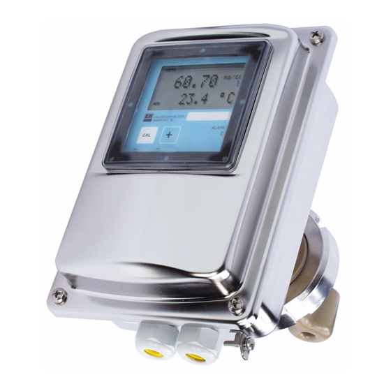
Measuring systems with inductive sensor for conductivity and concentration measurement in the food industry
Hide thumbs
Also See for Smartec CLD132:
- Operating instructions manual (52 pages) ,
- Operating instructions manual (82 pages)
Table of Contents

Related Manuals for Endress+Hauser Smartec CLD132


Summary of Contents for Endress+Hauser Smartec CLD132
- Page 1 Products Solutions Services BA00213C/07/EN/15.23-00 71616573 2023-04-30 Operating Instructions Smartec CLD132/134 Measuring systems with inductive sensor for conductivity and concentration measurement in the food industry PROFIBUS PA/DP...
-
Page 3: Table Of Contents
Smartec CLD132/134 PROFIBUS PA/DP Table of contents Table of contents Document information ....4 Protocol-specific data ....38 Warnings . -
Page 4: Document Information
Reference to page Reference to graphic Result of a step Symbols on the device Reference to device documentation Documentation Operating Instructions for Smartec CLD132, BA00207C Operating Instructions for Smartec CLD134, BA00401C Guidelines for planning and commissioning PROFIBUS DP/PA, BA00034S Endress+Hauser... -
Page 5: Basic Safety Instructions
Intended use Smartec CLD132 and CLD134 are measuring systems for measuring conductivity. The PROFIBUS interface allows the device to be operated using a plant asset management tool, e.g. FieldCare, or a commissioning tool,e.g. DeviceCare, on the PC. -
Page 6: Product Safety
Basic safety instructions Smartec CLD132/134 PROFIBUS PA/DP During operation: ‣ If faults cannot be rectified: products must be taken out of service and protected against unintentional operation. Product safety The product is designed to meet state-of-the-art safety requirements, has been tested, and left the factory in a condition in which it is safe to operate. -
Page 7: Incoming Acceptance And Product
Smartec CLD132/134 PROFIBUS PA/DP Incoming acceptance and product identification Incoming acceptance and product identification Incoming acceptance 1. Verify that the packaging is undamaged. Notify the supplier of any damage to the packaging. Keep the damaged packaging until the issue has been resolved. -
Page 8: Scope Of Delivery
Incoming acceptance and product identification Smartec CLD132/134 PROFIBUS PA/DP 4. Click the product overview. A new window opens. Here you fill information pertaining to your device, including the product documentation. Scope of delivery CLD132 The scope of delivery of the "compact version" with PROFIBUS comprises: •... -
Page 9: Installation
Smartec CLD132/134 PROFIBUS PA/DP Installation Installation System architecture A complete measuring system consists of • CLD132 or CLD134 transmitter with PROFIBUS PA or DP • Segment coupler (PA only) • PROFIBUS bus terminator • Cabling incl. bus distributor • Programmable Logic Controller (PLC) or PC with FieldCare or DeviceCare... -
Page 10: Mounting The Measuring Device
Smartec CLD132/134 PROFIBUS PA/DP Mounting the measuring device ‣ Carry out installation in accordance with the operating instructions. Operating Instructions for Smartec CLD132, BA00207C Operating Instructions for Smartec CLD134, BA00401C Post-installation check 1. After installation, check the measuring system for damage. -
Page 11: Electrical Connection
Prior to commencing connection work, ensure that no voltage is present on any cable. Connecting the measuring device ‣ Set up the electrical connection according to the operating instructions. Operating Instructions for Smartec CLD132, BA00207C Operating Instructions for Smartec CLD134, BA00401C Connecting the bus cable Feeding the cable into the housing A0051920 ... - Page 12 Electrical connection Smartec CLD132/134 PROFIBUS PA/DP 99 98 95 94 78 85 86 93 94 81 82 99 98 95 94 78 85 86 93 94 81 82 PA– PA– Pg 13.5 A0052496 Connect the cable cores of the bus cable to the terminal block. Mixing up the polarity of the PA + and PA- connections has no effect on operation.
-
Page 13: Post-Connection Check
Smartec CLD132/134 PROFIBUS PA/DP Electrical connection Bus termination The bus terminations for PROFIBUS PA and DP are different. • Each PROFIBUS PA bus segment must be terminated with apassive bus terminator on each end. • Each PROFIBUS DP bus segment must be terminated with anactive bus terminator on each end. -
Page 14: Operation
Operating Instructions for Smartec CLD134, BA00401C Operation via FieldCare or DeviceCare Fieldcare is the FDT-based plant asset management tool from Endress+Hauser. It can configure all intelligent field devices in your plant and help you manage them. By using status information, it also provides a simple but effective means of monitoring the devices. -
Page 15: System Integration
Smartec CLD132/134 PROFIBUS PA/DP System integration System integration PROFIBUS PA/DP block model In the PROFIBUS configuration, all the device parameters are categorized according to their functional properties and tasks and are generally assigned to three different blocks. A block may be regarded as a container in which parameters and the associated functions are contained (see ). - Page 16 The following entries are permitted: 2457: Device data can be overwritten (factory setting) 0: Device data cannot be overwritten Operating Instructions for Smartec CLD132, BA00207C 7.1.3 Parameter LOCAL_OP_ENABLE Use this parameter to either allow or lock local operation on the device.
- Page 17 Smartec CLD132/134 PROFIBUS PA/DP System integration Using local operation, you can either reset all data to the factory settings or delete the sensor data in menu field S10 (SERVICE function group). 7.1.6 Parameter IDENT_NUMBER_SELECTOR Using this parameter, you can switch the transmitter between three different mode of...
- Page 18 System integration Smartec CLD132/134 PROFIBUS PA/DP 7.1.9 SIMULATE In the SIMULATE parameter group, you can replace the input value with a simulation value and activate simulation. By specifying the status and the simulation value, you can test the response of the automation system.
- Page 19 Smartec CLD132/134 PROFIBUS PA/DP System integration The following status values can be displayed: • GOOD_NON_CASCADE The output value OUT is valid and be used for further processing. • UNCERTAIN The output value OUT can only be used for further processing to a limited extent.
-
Page 20: Cyclic Data Exchange
System integration Smartec CLD132/134 PROFIBUS PA/DP Example: • The system unit in the transducer block is °C. • The measuring range of the device is –10 to 150 °C. • The output range in relation to the automation system should be 14 °F ... 302 °F. - Page 21 Smartec CLD132/134 PROFIBUS PA/DP System integration • Main Process Value This byte transfers the primary value. • Temperature This byte transfers the temperature. • MRS Measuring Range Switch This byte is used to transmit the external hold and parameter set changeover from the PLC to the transmitter.
- Page 22 System integration Smartec CLD132/134 PROFIBUS PA/DP Byte 1 Byte 2 Byte 3 Byte 4 − − − − − − − − − − − − − − − − − − − − − − − Exponent Mantissa Formula...
- Page 23 Smartec CLD132/134 PROFIBUS PA/DP System integration Status codes for the OUT parameter of the Analog Input Block Status code Device status Meaning Limits 0x00 Not specific 0x01 LOW_LIM 0x02 HIGH_LIM 0x03 CONST 0x04 Configuration error 0x05 LOW_LIM 0x06 HIGH_LIM 0x07...
-
Page 24: Acyclic Data Exchange
System integration Smartec CLD132/134 PROFIBUS PA/DP Acyclic data exchange Acyclic data exchange is used to transfer parameters during commissioning and maintenance or to display other measured variables that are not contained in cyclic data traffic. Generally, a distinction is made between Class 1 and Class 2 master connections. - Page 25 Smartec CLD132/134 PROFIBUS PA/DP System integration Parameter Matrix Slot Index Size Type Acc. Store (bytes) MODE_BLK DS-37* Actual Unsigned8 Permitted Unsigned8 Normal Unsigned8 ALARM_SUM DS-42* Block parameter SOFTWARE_REVISION Visible string HARDWARE_REVISION Visible string DEVICE_MAN_ID Unsigned16 DEVICE_ID Visible string DEVICE_SER_NUM Visible string...
- Page 26 System integration Smartec CLD132/134 PROFIBUS PA/DP Parameter Matrix Slot Index Size Type Acc. Store (bytes) GLOBAL_STATUS Unsigned16 200 - E +H parameter ACTUAL_ERROR VAH2 Unsigned16 LAST_ERROR VAH3 Unsigned16 UPDOWN_FEATURES_SUPP Octetstring DEVICE_BUS_ADRESS VAH1 Signed8 SET_UNIT_TO_BUS VAH9 Unsigned8 r, w 0: off...
- Page 27 Smartec CLD132/134 PROFIBUS PA/DP System integration Parameter Matrix Slot Index Size Type Acc. Store (bytes) NUMBER_OF_RANGES 1 - 2 Unsigned8 RANGE_1 1 - 2 DS-61* r, w 7.3.5 Analog Input Block Two Analog Input Blocks are provided. These are distributed to slots 1 and 2 in the following order: 1.
- Page 28 System integration Smartec CLD132/134 PROFIBUS PA/DP Parameter Matrix Slot Index Size Type Acc. Store (bytes) SIMULATE 1 - 2 DS-50* r, w VIEW_1 1 - 2 Unsigned8 7.3.6 Manufacturer-specific parameters Parameter Matrix Slot Index Size Type Acc. Store (bytes) Measured value...
- Page 29 Smartec CLD132/134 PROFIBUS PA/DP System integration Parameter Matrix Slot Index Size Type Acc. Store (bytes) Mode of operation for processed V4h3 Unsigned8 r, w measuring range 0: Conductivity 1: Concentration Substance selection for processed V4H4 Unsigned8 r, w measuring range...
- Page 30 System integration Smartec CLD132/134 PROFIBUS PA/DP Parameter Matrix Slot Index Size Type Acc. Store (bytes) Alpha table status V6H6 Unsigned8 0: OK 1: Service 2: Processing 3: Invalid PCS alarm V7H0 Unsigned8 r, w 0: No PCS 1: 1 hour...
-
Page 31: Commissioning
Smartec CLD132/134 PROFIBUS PA/DP Commissioning Commissioning Function check Before commissioning the measuring point, make sure that all final checks have been carried out: • "Post-installation" checklist • "Post-connection" checklist Configuring the device address The address must always be set for each PROFIBUS device. The control system does not recognize the transmitter if the address is not set correctly. - Page 32 Commissioning Smartec CLD132/134 PROFIBUS PA/DP A0051962 8 DIL switch 8 must be set to ON to allow operation via software. Set the device address using the INTERFACE function group in the I1 menu field. CODE USER INTERFACE SELECTION (factory...
-
Page 33: Device Master Files
PLC from the device and in which format. Each device is assigned an ID number by the PROFIBUS user organization (PNO). The name of the GSD is derived from this number. For Endress+Hauser, this ID number starts with the manufacturer ID 15xx. For easier classification and greater... - Page 34 8.3.3 Content structure of the GSD files from Endress+Hauser For the Endress+Hauser transmitter with PROFIBUS interface, you receive an exe file containing all of the files required for configuration. This file creates the following structure when automatically unpacked: The available measuring parameters of the transmitter are at the top level. Below this level, you have: •...
-
Page 35: Diagnosis And Troubleshooting
Smartec CLD132/134 PROFIBUS PA/DP Diagnosis and troubleshooting Diagnosis and troubleshooting System error messages The DIAGNOSIS and DIAGNOSIS_EXTENSION parameters are generated from the device- specific errors. NAMUR Error Description DIAGNOSIS DIAGNOSIS_ Measured value status class EXTENSIO Quality Sub-status Failure E001 Memory error... -
Page 36: Process And Device-Specific Errors
Live check alarm (PCS) 20 00 00 80 - DIA_MEASUREMENT 00 00 00 02 00 00 sensor failure Depending on the status of the limit bits, 00 to 03 is added. Process and device-specific errors Operating Instructions for Smartec CLD132, BA00207C Operating Instructions for Smartec CLD134, BA00401C Endress+Hauser... -
Page 37: Communication-Specific
Smartec CLD132/134 PROFIBUS PA/DP Communication-specific accessories Communication-specific accessories M12 fieldbus connector set • Four-pin metal connector for mounting on the transmitter • For connecting to the junction box or cable socket • Cable length 150 mm (5.91 in) • Order No. 51502184 150 (5.91) -
Page 38: Protocol-Specific Data
Protocol-specific data Smartec CLD132/134 PROFIBUS PA/DP Protocol-specific data 11.1 PROFIBUS-PA Output signal PROFIBUS-PA: EN 50170 vol. 2, Profile version 3.0 PA function Slave Transmission rate 31.25 kbps Signal coding Manchester II Slave response time Approx. 20 ms Signal on alarm Status and alarm messages in accordance with PROFIBUS-PA, profile version 3.0 Display: error... -
Page 39: Standards And Guidelines
Smartec CLD132/134 PROFIBUS PA/DP Protocol-specific data 11.4 Standards and guidelines PROFIBUS EN 50170, vol. 2 PROFIBUS-DP EN 50170, vol. 2 RS 485 PNO guidelines for PROFIBUS-DP PROFIBUS-PA EN 50170, vol. 2 IEC 61158-2 PNO guidelines for PROFIBUS-PA Endress+Hauser... -
Page 40: Index
Index Smartec CLD132/134 PROFIBUS PA/DP Index Connecting the bus cable ..... . 11 Device address ......31 Device master files . - Page 44 *71616573* 71616573 www.addresses.endress.com...