Table of Contents
Advertisement
Available languages
Available languages
Quick Links
Original instructions
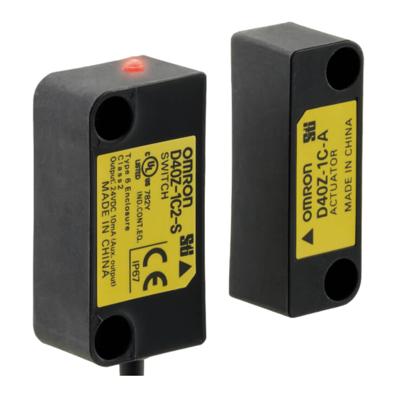
Type D40Z
Compact Non-Contact Door Switch
The D40Z non-contact door switch provides a
safety-related interruption at a specified proximity
position of its actuator through a safety controller.
INSTRUCTION MANUAL
English
Thank you for purchasing D40Z Compact Non-contact
Door Switch.
Please read and understand this manual before using
the products.
Keep this manual ready to use whenever needed.
Only qualified person trained in professional electrical
technique should handle D40Z.
Please consult your OMRON representative if you have
any questions or comments.
Make sure that information written in this document are
delivered to the final user of the product.
2137840-7E
© OMRON Corporation 2010-2022 All Rights Reserved.
Instructions in the EU languages and a signed EU Declaration of Conformity
are available on our website at http://www.industrial.omron.eu/safety.
Declaration of Conformity
OMRON declares that D40Z is in conformity with the requirements
of the following EU Directives and UK Legislation:
EU: Machinery Directive 2006/42/EC, EMC Directive 2014/30/EU,
RoHS Directive 2011/65/EU
UK: 2008 No. 1597 Machinery (Safety), 2016 No. 1091 EMC,
2012 No. 3032 RoHS
Safety Standards
D40Z is designed and manufactured in accordance with the
following standards:
EN ISO13849-1:2015 Cat. 4 PL e (with G9SX-NS),
IEC/EN61508 SIL3 (with G9SX-NS)
IEC/EN60947-5-3 PDDB (with G9SX-NS),
IEC/EN61000-6-4, EN ISO 14119 (Low level coded),
UL508, CAN/CSA C22.2 No.14
Safety Precautions
Meaning of Warning Sign
The following warning sign is used in this manual.
Indicates a potentially hazardous situation which,
if not avoided, will result in minor or moderate
WARNING
injury, or may result in serious injury or death.
Additionally there may be significant property
damage.
Alert Statements
WARNING
Machine may start operating and may result serious injury
or death. Do not put the actuator close to the switch when
the door is opened. Also make sure to install D40Z to
minimize defeat possibilities. For required measures, refer
to ISO 14119 and other relevant standards and regulations.
Precautions for Safe Use
(1) Disconnect D40Z from power supply when wiring D40Z. Failure to do
so may cause unexpected operation of devices connected to D40Z.
(2) Do not operate D40Z with flammable or explosive gas.
(3) Incorrect wiring may lead to loss of safety function. Wire
conductors correctly and verify the operation of D40Z before using
the system in which D40Z is incorporated.
(4) Auxiliary monitoring output is NOT safety output. Do not use auxiliary
monitoring output individually for any safety function. Such incorrect
use causes loss of safety functions of D40Z and its relevant systems.
(5) After installation of D40Z, qualified personnel should verify to see that the
installation, inspection, and maintenance are properly performed. The qualified
personnel should be qualified and authorized to secure the safety on each
phases of design, installation, running, maintenance and disposal of system.
(6) Qualified personnel, who are familiar to the machine in which
D40Z is to be installed, should conduct and verify the installation.
(7) Be sure to inspect D40Z daily and every 6 months. Otherwise,
serious injury may possibly occur due to a system malfunction.
(8) Do not dismantle, repair, or modify D40Z. Doing so may lead to
loss of its safety functions.
(9) Do not apply DC voltages exceeding the rated voltages, nor any
AC voltages to D40Z.
(10) Use a DC supply satisfying the requirements given below to
prevent electric shock.
- DC power supply or transformer with double or reinforced
insulation, for example, according to IEC/EN 62368 or IEC/EN
61558.
- A DC supply satisfying the requirements for class 2 circuits or
limited voltage/current circuits stated in UL 508.
(11) Use only appropriate components or devices complying with
relevant safety standards corresponding to the required
performance level and safety category. Conformity to requirements
of the performance level and safety category must be determined as
an entire system. It is recommended to consult a certification body
regarding assessment of conformity to the required safety level.
Precautions for Correct Use
(1) Always use D40Z with dedicated actuator (D40Z-1C-A) and dedicated
controller to comply with the requirements of EN ISO 13849-1.
(2) Handle with care
Do not drop D40Z to the ground or expose to excessive vibration or
mechanical shocks. Doing so may damage D40Z and cause failure.
(3) Conditions of storage and usage
Do not store or use D40Z under the following conditions. Doing so
may damage D40Z and cause failure.
1) In direct sunlight
2) At ambient temperatures out of the range of -10 to +65°C
3) At relative humidities out of the range of 25% to 85% or under
such temperature change that causes condensation.
4) In corrosive or combustible gases
5) With vibration or mechanical shocks out of the rated values.
6) Under splashing of oil or chemicals
7) In the atmosphere containing dust, saline or metal powder.
8) Where steel scrap or metal powder may fall directly to D40Z.
(4) Do not use D40Z at altitudes over 1,000 meters.
(5) Do not use to connect other switches or sensors to the wire
conductors of D40Z.
(6) Disconnect D40Z and the controller connected to D40Z from power
supply when replacing D40Z. Failure to do so may cause
unexpected operation of devices connected to D40Z.
(7) Keep D40Z from solvent such as alcohol, thinner, trichloroethane or
gasoline. Such solvents make the marking on D40Z illegible and
cause deterioration of parts.
(8) Do not use D40Z in the magnetic field of 1.5 mT or more, otherwise
D40Z may not function properly.
(9) Do not use D40Z in the water or continuous water exposure environment,
otherwise water may leak into D40Z. (An enclosure of IP67 rating, which
D40Z is rated, protects against temporary immersion in water.)
(10) Do not use D40Z switch or actuator as a stopper. Use a stopper to
protect the switch and the actuator. Keep a distance of at least
1mm between the switch and the actuator.
(11) Be sure to install D40Z switch and actuator in such as appropriate
distance that does not create a gap accessible to the hazard.
(12) When two or more Switches are mounted side-by-side, they must
be no closer than 50 mm in the X, Y, and Z directions.
50mm min.
50mm min.
(13) Be sure that the machine is stopped whenever the guard door
is open.
(14) Installing the switch and actuator on a metallic material may affect the
operating distance. In addition, any instruments nearby that generate strong
radio waves or magnetic fields may affect the operating distance via the
metal. Do not install the switch and actuator directly on a metallic material.
If installation on a metallic material is necessary, be sure to check the effect
on the operating distance before use. Reference values for the effects of
installation on a metallic material.
Metallic material
Operating distance
Iron
Approximately 75% of the original value
Aluminum
Approximately 85% of the original value
Stainless steel
Approximately 85% of the original value
(Non-magnetic substance)
It is recommended that the switch and actuator unit be separated
at least 10 mm from any metal parts or metallic materials.
(15) Use M4 screws and washers to install the switch and actuator.
Tighten the screws with a specified torque. After installing and
commissioning, coat the switch-actuator fixing screws with
tamper-proof varnish or similar compound for locking. Using
anaerobic locking compounds can have a detrimental effect on
the plastic switch case if the compounds contact with the switch case.
Switch
(16) Wiring:
1.Use conductors of the following sizes to wire D40Z:
-Stranded wire: 0.2 to 2.5mm
AWG24 to AWG12
2
-Solid wire: 0.2 to 2.5mm
AWG24 to AWG12
2
2.When not using auxiliary output, cut off the unused conductors and
protect by insulating-taping to prevent contacting with other terminals.
3.When you use an additional cable of 20m or longer, use a
multiconductor cable to group the white, black, brown, and
blue lines together.
(17) Use cables of a total length of 100m max. to connect multiple
D40Z switches. However, the total length of 200m max. is possible
depending on the number of D40Z switches connected. The
supply voltage to D40Z may decrease by the voltage drop
depending on the cable or the wiring configuration. Check the
power-supply voltage is in the rated range.
30 or less D40Z connected
15 or less D40Z connected
(Note)
Total wiring length
100m max.
D1 D2 D3 D4
D1 D2 D3 D4
G9SX-NS202
G9SX-NS202
G9SX-NSA222
G9SX-NSA222
Note. The wiring length between the products must be 100m max.
(18) In a residential environment, this product may cause radio
interference, in which case the user may be required to take
adequate measures.
(19) D40Z may not function properly in surrounding environment with strong
electromagnetic equipment such as RFID system, proximity sensor, motor,
inverter, and switching power supply. If you use D40Z near such equipment,
be sure to verify effects of such equipment on D40Z before using.
(20) Handle cables with care:
1) For bending cables, it is recommended to bend them with a
radius of bend no less than six times the cable outer diameter.
2) Do not apply a tensile strength of 50N or greater to the cables.
(21) To determine safety distance to hazards, take into account the
delay of non-contact door switch output caused the response time.
(22) If there is any machine that has a large surge current (e.g., a motor) near
D40Z, connect a surge absorber to D40Z between the blue and the other
cables (white, black, and brown), respectively, and between the yellow and
the gray cables. Suggested surge absorber's specification is as follows:
- Peak pulse power: 600W (10/1000µs) or more
(Per IEC61000-4-5(surge immunity))
- Breakdown voltage: 27-33V
1
Detection Ranges (Engineering data)
5mm (point A)
15mm (point B)
Y-direction movement
Target marks
Unstable
* The movement of the arrow
ON
OFF
range
18
18
Maximum
16
OFF range
operating distance
16
(ON to OFF)
14
14
Main lobes
B
Engineering Data
Main lobes
(ON to OFF)
12
12
Engineering Data
10
(OFF to ON)
10
8
Minimum
8
operating
6
distance
6
(OFF to ON)
4
A
4
Side lobe
Side lobe
(Y<3mm)
(Y<3mm)
2
ON range
2
0
0
-35 -30 -25 -20-15 -10 -5 0 5 10 15 20 25 30 35
-30 -25 -20 -15 -10 -5 0 5 10 15 20 25 30
Distance from the target mark on the switch X (mm)
Distance from the target mark on the switch Z (mm)
Note1. Operating distance means the distance of the sensing surfaces
between the switch and actuator.
Note2. Above graph is only for reference temperature at 23°C.
Actual operating distance may vary depending on the
surrounding metals or temperature.
Note3. Surfaces other than the sensing surfaces of the switch and
actuator may activate the detection. Be sure to install the switch
and actuator so that the sensing surfaces oppose one another,
according to the following "2. Switch and Actuator Operation"
2
Switch and actuator operation
Switch and Actuator Mounting Directions
Switch
Switch
Actuator
Switch and Actuator Operating Directions
Note. When using the operating direction along the sensing surface,
be sure to install the switch and actuator so as not to be affected
by the side lobe.
LED Display
LED color
Status
ON: Switch does NOT detect actuator.
RED
Blinking: Switch detects a fault.
ON: Switch detects actuator.
Blinking: Switch detects actuator,
YELLOW
and non-contact door switch signal input is in OFF state.
50mm min.
3
Ratings and Specifications
Ratings
Item
Supply voltage
Power consumption (Note 1)
Auxiliary output
Specification and Performance
Item
OFF to ON
Assured
ON to OFF
operating and
Differential travel
release
distance
Temperature influence
(Note 2)
Repeat accuracy (max.) ±10% of operating distance at 23°C
Switching frequency
Response time (ON to OFF)
Operating time (OFF to ON)
Ambient temperature
Actuator
Ambient humidity
Insulation resistance
(Between all conductive parts
and switch case)
Dielectric strength
M4
(Between all conductive parts
1N . m
and switch case)
Rated impulse withstand voltage 1 kV
Vibration resistance
Shock resistance
Pollution degree
Electromagnetic compatibility
Degree of protection
Material
Mounting method
Tightening torque
Weight (D40Z-1C5)
Safety-related characteristic
data (EN 61508:2010)
5
Connection Example
(Note)
Single switch connection
Total wiring length
with G9SX-NS
200m max.
(Note)
D1 D2 D3 D4
G9SX-NS202
G9SX-NSA222
Internal connection
Sensing
X
surface
LED indicator
Z*
Y
OFF
direction indicates the positive
direction on the graph.
Maximum
operating distance
OFF range
(ON to OFF)
Engineering
B
Red continuously
Data
(ON to OFF)
blinking
Engineering
Data
(OFF to ON)
Minimum
operating
distance
(OFF to ON)
A
Red blinks once for 2s
ON range
Red blinks twice for 2s
Red blinks thrice for 2s
Yellow
Blinking
Red Solid-ON (Note 2)
Yellow Solid-ON
(Note 3)
Actuator
Note1. Another possible cause is a failure in internal circuit. In this case, replace with a new D40Z.
Yet another possible cause is excessive noise. In this case, check and correct ambient noise environment.
Note2. Troubleshooting when the actuator is not detected (Red Solid-ON) although the guard door is closed.
(Note)
Note3. Troubleshooting when the system stops although the guard door is closed and the actuator is detected (Yellow Solid-ON).
Omron Companies shall not be responsible for conformity with any
standards, codes or regulations which apply to the combination of the
Product in the Buyer's application or use of the Product. At Buyer's request,
Omron will provide applicable third party certification documents identifying
ratings and limitations of use which apply to the Product. This information by
itself is not sufficient for a complete determination of the suitability of the
Product in combination with the end product, machine, system, or other
application or use. Buyer shall be solely responsible for determining
appropriateness of the particular Product with respect to Buyer's application,
product or system. Buyer shall take application responsibility in all cases.
NEVER USE THE PRODUCT FOR AN APPLICATION INVOLVING
SERIOUS RISK TO LIFE OR PROPERTY OR IN LARGE QUANTITIES
WITHOUT ENSURING THAT THE SYSTEM AS A WHOLE HAS BEEN
DESIGNED TO ADDRESS THE RISKS, AND THAT THE OMRON
PRODUCT(S) IS PROPERLY RATED AND INSTALLED FOR THE
INTENDED USE WITHIN THE OVERALL EQUIPMENT OR SYSTEM.
Note1. Power consumption of loads is not included.
Note2. This is the distance where the switch operates from OFF to ON when
approaching and the distance where the switch operates from ON to
OFF when separating when the switch and actuator target marks are
D40Z-1C
on the same axis, and the sensing surfaces coincide.
Note3. The value of Non-contact door switch output is indicated.
24 VDC +10% / -15%
Performance Level / Safety Category
0.5 W max.
Photocoupler output: 24 V DC,
D40Z can achieve the corresponding performance levels and
load current: 10 mA
categories up to PL e and Category 4 per EN ISO 13849-1 by
the combined use with the controller G9SX-NS.
Note that the performance levels and categories are based on the example
D40Z-1C
circuits that we recommend. This does NOT mean that the combination of
D40Z and G9SX-NS can always achieve the performance levels and
5 mm min.
categories under all the similar conditions and situations.
UL does not provide UL certification for any functional safety
15 mm max.
rating or aspects of the D40Z device.
See 1 Detection ranges
Conformity to the performance levels and categories must be assessed as
a whole system. When using D40Z and G9SX-NS for the performance
See 1 Detection ranges
levels and safety categories, perform the installation, inspection, and
maintenance properly, and make sure the conformity of the whole system.
1 Hz with G9SX-NS
25 ms max.
• Daily inspection:
(Note 3)
1. Check every guard door to see that machine stops
100 ms max.
when guard door is opened.
(Note 3)
(for a 5-mm distance between sensing
• 6-month inspection:
surfaces of switch and actuator)
1. Isolate all power.
-10 to +65°C
2. Check the switch and actuator for proper alignment.
(with no icing or condensation)
3. Check terminals for proper connections.
25 to 85%RH
4. Check wiring for signs of damage.
5. Before resuming normal machine operation, check every guard
50 Mohm min.
door to see that machine stops when the guard door is opened.
(at 500 VDC megger)
4
Dimensions
Switch
1000 VAC for 1min
10 to 55 to 10 Hz (single amplitude:
0.75 mm, double amplitude: 1.5 mm)
300 m/s
min.
2
3
As per IEC/EN 60947-5-3
IP67
Molded PBT
Two. 7.2 dia.
M4 screws
.
Actuator
1N
m
Switch: approx. 175 g
Actuator: approx. 20 g
See http://www.fa.omron.
co.jp/safety_6en/
Two. 4.2 dia.
Multiple switch connection with G9SX-NS
Maximum 30 switches connectable in series
Note 1. Maximum auxiliary output current is 10mA.
D1 D2 D3 D4
G9SX-NS202
Note 2. Refer to the D40Z catalog for other types of wiring.
G9SX-NSA222
Wiring
Color of
Signal Name
Description of Operation
brown
Conductor
+
Non-contact door switch
Brown
blue
Power supply for D40Z
-
power input
Blue
white
To set non-contact door switch output in ON state,
Non-contact door switch
White
black
non-contact door switch signal input must be in ON state.
signal input
Non-contact door switch
Output status depends on statuses of actuator and
yellow
Black
non-contact door switch signal input.
Output
gray
Yellow
Output status depends on status of actuator.
Auxiliary monitoring
Output
When a fault is detected, turns into OFF state regardless of actuator status.
Gray
Troubleshooting
Causes and Corrective Action (Note 1)
Power supply input may be improperly wired. Check and correct wiring of brown and blue lines.
Refer to Section 5. Connection Examples.
Power supply to D40Z may be insufficient.
Fault in power supply
Check the power-supply voltage of D40Z fills ratings. Refer to Section 3. Ratings and Specification.
Input (brown/blue)
The wiring length or size of the wire may not be to the specification.
Check the wiring length and size of the wire. Refer to Precautions for Correct Use.
There may be excessive noise. Check and correct ambient noise environment.
Noise or
D40Z failure
There may be a failure in internal circuit. Replace with a new D40Z.
Power supply to D40Z may be insufficient.
Fault in power supply
Check the power-supply voltage of D40Z fills ratings. Refer to Section 3. Ratings and Specification.
Input (brown/blue)
The wiring length or size of the wire may not be to the specification.
Check the wiring length and size of the wire. Refer to Precautions for Correct Use.
Fault in Non-contact
Black line may be shorted to other line. Check and correct wiring of black line if the black line is
door switch output
shorted to other lines. Refer to Section 5. Connection Examples.
(black)
Invalid actuator may be in a close range to switch.
Sensing fault
Use the dedicated actuator.
Fault in Non-contact
Faulty signal may be input to white line. Check and correct wiring of white line.
door switch signal
Refer to Section 5. Connection Examples.
input (white)
Another D40Z may be in OFF state.
OFF state
Check status of another D40Z connected to the white line and the wiring.
of another D40Z
Refer to Section 2. Switch and actuator operation and Section 5. Connection Examples.
Fault in Non-contact
White line may be disconnected.
door switch signal
Check and correct wiring of white line.
input (white)
Refer to Section 5. Connection Examples.
Actuator fault
There may be a failure in actuator. Replace with a new D40Z.
Fault in Non-contact
White line connected to D1 terminal (test output terminal of G9SP) of G9SX-NS may be shorted to
door switch signal
other line. Check and correct wiring of white line connected to D1 terminal (test output terminal of G9SP)
input (white)
of G9SX-NS if the white line is shorted to other lines. Refer to Section 5. Connection Examples.
Fault in Non-contact
Black line connected to D2 terminal (safety input terminal of G9SP) of G9SX-NS may be disconnected.
door switch output
Check and correct wiring of black line connected to D2 terminal (safety input terminal of G9SP) of G9SX-NS.
(black)
Refer to Section 5. Connection Examples.
Suitability for Use
Inspection / Maintenance
1.5
2
20
25
(7.2 dia.)
5.5
Two. 4.2 dia.
38
10.5
48
16
12
17
(7.2 dia.)
Two. 7.2 dia.
38
7
16
48
Wiring example of
auxiliary output
The auxiliary output of D40Z supports
the input polarity of both PNP and NPN.
PNP
24VDC
Yellow
COM
PLC, etc
Gray
IN
NPN
Yellow
IN
PLC, etc
Gray
COM
24VDC
Incorrect wiring may damage the auxiliary output circuit.
OMRON Corporation
(Manufacturer)
Shiokoji Horikawa, Shimogyo-ku, Kyoto, 600-8530 JAPAN
Contact: www.ia.omron.com
Regional Headquarters
OMRON EUROPE B.V. (Importer in EU)
Wegalaan 67-69, 2132 JD Hoofddorp
The Netherlands
Tel: (31)2356-81-300/Fax: (31)2356-81-388
OMRON ELECTRONICS LLC
2895 Greenspoint Parkway, Suite 200
Hoffman Estates, IL 60169 U.S.A.
Tel: (1) 847-843-7900/Fax: (1) 847-843-7787
OMRON ASIA PACIFIC PTE. LTD.
438B Alexandra Road, #08-01/02
Alexandra Technopark,
Singapore 119968
Tel: (65) 6835-3011/Fax: (65) 6835-2711
OMRON (CHINA) CO., LTD.
Room 2211, Bank of China Tower,
200 Yin Cheng Zhong Road,
PuDong New Area, Shanghai, 200120, China
Tel: (86) 21-5037-2222/Fax: (86) 21-5037-2200
Advertisement
Table of Contents

Related Manuals for Omron D40Z


Summary of Contents for Omron D40Z
- Page 1 Actuator Actuator Note1. Another possible cause is a failure in internal circuit. In this case, replace with a new D40Z. (8) Do not use D40Z in the magnetic field of 1.5 mT or more, otherwise Switch and Actuator Operating Directions Yet another possible cause is excessive noise.
-
Page 2: Problembehebung
Schutzart IP67 und schützt vor dem vorübergehenden Eintauchen in Wasser.) Anmerkung 1. Eine andere mögliche Ursache ist ein Fehler in einem internen Schaltkreis. Wechseln Sie in diesem Fall den D40Z aus. Außerdem könnte die Ursache in übermäßigem Lärm bestehen. Überprüfen Sie und korrigieren Sie in diesem Fall den Umgebungs-Lärmpegel. -
Page 3: Manuel D'utilisation
Interrupteur Interrupteur manière à ne pas créer d'espace constituant une situation de danger. Remarque 1. Une panne du circuit interne peut être une autre cause possible. Dans ce cas, remplacer par un nouveau D40Z. Actionneur Actionneur En outre, le bruit excessif peut être une autre cause possible. Dans ce cas, vérifier et corriger le bruit de l'environnement. -
Page 4: Manual Del Usuario
D40Z. (Una caja de clasificación IP67, que es la clasificación de D40Z, Interruptor Nota 1. Otra causa posible es que haya un fallo en el circuito interno. En este caso, sustitúyalo por un D40Z nuevo. protege contra la inmersión temporal en el agua.) -
Page 5: Manuale Per L'utente
IP67, di cui il D40Z è certificato, Direzioni operative di interruttore e attuatore Nota 1. Un'altra possibile causa può essere un errore nel circuito interno. In questo caso, sostituire con un nuovo D40Z. protegge dall'immersione temporanea in acqua.) Un'ulteriore casua potrebbe essere l'eccessivo rumore. - Page 6 D40Z wordt vervangen. Als dat niet wordt gedaan, kunnen Opmerking 1. Een andere mogelijke oorzaak is een fout in het interne circuit. Vervang in dit geval door een nieuwe D40Z. apparaten die op de D40Z aangesloten zijn, onverwacht gaan werken.
- Page 7 D40Z eventuelt ikke fungere korrekt. Kontakt Kontakt Bemærk 1. En anden mulig årsag er fejl i det interne kredsløb. I dette tilfælde skal du udskifte med en ny D40Z. (9) Brug ikke D40Z i vand eller et miljø med kontinuerlig Aktuator Aktuator En anden mulig årsag er for megen støj.
- Page 8 (11) Käytä vain edellytettyä toimintatasoa ja turvallisuusluokkaa D40Z:n virransyöttö ei ehkä ole riittävän tehokas. tulossa vastaavien turvallisuusstandardien mukaisia asianmukaisia Tarkista, että D40Z:n virransyötön jännite on tyyppiarvojen mukainen. Katso osion 3. tyyppiarvot ja tekniset tiedot. Y-suuntainen liike Kohdemerkit (ruskea/sininen) komponentteja tai laitteita. Toimintataso- ja Johdotuksen pituus tai johtojen koot eivät ehkä...
- Page 9 Omkopplarens och manöverdonets funktionsriktningar Anm. 1. En annan möjlig orsak är ett fel i den interna kretsen. Byt i så fall ut mot en ny D40Z. (8) Använd inte D40Z i ett magnetfält på 1,5 mT eller mer; i så fall Ytterligare en möjlig orsak är kraftigt oljud.
-
Page 10: Instrukcja Obsługi
(6) Na czas wymiany czujnika D40Z należy go wraz z podłączonym do niego Uwaga 1. Możliwe, że w obwodzie wewnętrznym występuje inna usterka. W takim przypadku należy dokonać wymiany czujnika D40Z na nowy. sterownikiem odłączyć od źródła zasilania. W przeciwnym wypadku może dojść... -
Page 11: Инструкция По Эксплуатации
См. раздел 5. Примеры подключения. портят маркировку на D40Z и приводят к порче деталей. Примечание 1. Другая возможная причина – неисправность внутренней цепи. В этом случае замените новым D40Z. (8) Не используйте D40Z при наличии магнитного поля 1,5 мТл или... -
Page 12: Manual De Instruções
(11) Utilize apenas componentes apropriados ou dispositivos compatíveis com alimentação Confirme se a tensão de alimentação do D40Z preenche as classificações. Consulte a Secção 3. Classificações e Especificações. (castanha/azul) normas de segurança relevantes, de acordo com o nível de desempenho e O comprimento ou o tamanho do cabo pode não corresponder às especificações. -
Page 13: Kullanim Kilavuzu
(8) D40Z'yi 1,5 mT veya daha büyük manyetik alanda kullanmayın, Aktüatör Aktüatör Not1. Bir başka olası neden, dahili devredeki bir arızadır. Bu durumda, yeni bir D40Z ile değiştirin. aksi takdirde D40Z doğru çalışmayabillir. Anahtar ve Aktüatör Çalışma Yönleri Yine bir başka olası neden aşırı gürültüdür. Bu durumda, çevre gürültüsü ortamını kontrol edin ve düzeltin.