Table of Contents
Advertisement
Quick Links
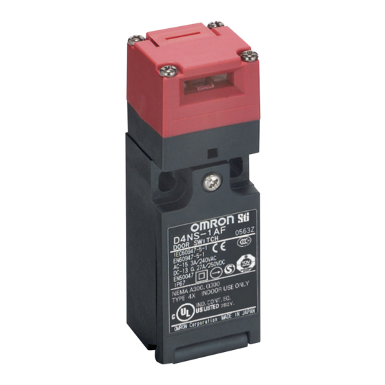
Safety-door Switch
D4NS/D4NS-SK
Multi-contact, Labor-saving,
Environment-friendly, Next-
generation Safety-door Switch
• Lineup includes three contact models with 2NC/1NO
and 3NC contact forms and MBB models in addition
to the previous contact forms 1NC/1NO, and 2NC.
• M12-connector models are available, saving on
labor and simplifying replacement.
• Standardized gold-clad contacts provide high
contact reliability.
Applicable to both standard loads and microloads.
• Variety of metallic heads available.
Be sure to read the "Safety Precautions" on page 12.
Model Number Structure
Model Number Legend
Switch (Standard type)
D4NS-@@@
1 2 3
1. Conduit Outlet/Connector
1:Pg13.5 (1-conduit type)
2:G1/2 (1-conduit type)
4:M20 (1-conduit type)
6:G1/2 (2-conduit type)
8:M20 (2-conduit type)
9:M12 connector (1-conduit type)
2. Built-in Switch
A:1NC/1NO (slow-action)
B:2NC (slow-action)
C:2NC/1NO (slow-action)
D:3NC (slow-action)
E:1NC/1NO (MBB contact)
F:2NC/1NO (MBB contact)
3. Head Mounting Direction
F:Four mounting directions possible (Front-side mounting at
shipping)/plastic
D:Four mounting directions possible (Front-side mounting at
shipping)/metal
Note: An order for the head part or the switch part alone cannot be
accepted. (The Operation Key is sold separately.)
Safety Door Switchs
Slide Keys
For the most recent information on models that have been certified for
safety standards, refer to your OMRON website.
Switch (High pull-force type)
D4NS-@@F-SJ
1 2
1. Conduit Outlet
2:G1/2 (1-conduit type)
4:M20 (1-conduit type)
2. Built-in Switch
A:1NC/1NO (slow-action)
B:2NC (slow-action)
C:2NC/1NO (slow-action)
D:3NC (slow-action)
Operation Key
D4DS-K@
1
1. Operation Key Type
1:Horizontal mounting
2:Vertical mounting
3:Adjustable mounting (Horizontal)
5:Adjustable mounting (Horizontal/Vertical)
CSM̲D4NS_D4NS-SK̲DS̲E̲9̲4
1
Advertisement
Table of Contents

Related Manuals for Omron D4NS


Summary of Contents for Omron D4NS
- Page 1 Be sure to read the “Safety Precautions” on page 12. Slide Keys For the most recent information on models that have been certified for safety standards, refer to your OMRON website. Model Number Structure Model Number Legend Switch (Standard type)
-
Page 2: Ordering Information
D4NS/D4NS-SK Ordering Information Switches (Operation Keys are sold separately.) Consult with your OMRON representative when ordering any models that are not listed in this table. Type Contact configuration Conduit outlet/Connector Model Pg13.5 D4NS-1AF * 1NC/1NO G1/2 D4NS-2AF * D4NS-4AF Pg13.5... -
Page 3: Operation Keys
20,000 operations min. Receptacle bracket: 1 Slide Key: 1 (Disable-prevention cover and Operation Key D4DS-K2 are already mounted on Slide Key) Weight: 2,800 g D4NS mounting tool: 1 D4NS Mechanical durability: Inner lever: 1 D4NS-SK30 1-conduit type 20,000 operations min. - Page 4 D4NS/D4NS-SK Slide Keys D4NS-SK01 Configration Ideal for 20 x 20-mm aluminum frame doors D4NS-SK01 D4NS 1-conduit type D4NS-SK30 Configration For safety measures on large doors D4NS-SK30 D4NS 1-conduit type Close door. Magnetic catches prevent the operator from accidentally opening the door.
-
Page 5: Specifications
Although the switch box is protected from dust or Interlock type Type 2 (EN ISO 14119) water penetration, do not use the D4NS in places where foreign Coding level Low level coded (EN ISO 14119) material may enter through the key hole on the head, otherwise Switch damage or malfunctioning may occur. - Page 6 D4NS/D4NS-SK Structure and Nomenclature Structure D4NS-@A@, D4NS-@B@, D4NS-@E@, D4NS-@C@, D4NS-@D@, D4NS-@F@, D4NS-@AF-SJ, D4NS-@BF-SJ D4NS-@CF-SJ, D4NS-@DF-SJ Operation Head key hole The head can be mounted in four directions. Sealing properties The switch casing ensures IP67 Terminal 11 Terminal 12 Terminal 11...
- Page 7 D4NS/D4NS-SK Dimensions (Unit: mm) Dimensions and Operating Characteristics 1-Conduit Types Head cap D4NS-1@F D4NS-2@F D4NS-4@F D4NS-2@F-SJ D4NS-4@F-SJ Model D4NS-1@F D4NS-2@F-SJ D4NS-2@F Operating 30.2 30.6 D4NS-4@F-SJ D4NS-4@F characteristics 15.5 15.3 Key insertion force 15 N max. 15N max. Key extraction force 30 N max.
- Page 8 Four, M5 tap screws P=0.8 Stroke 45.5 60 Switch Mounting Pattern 1 Switch Mounting Pattern 2 42.5 Assembled 74 max. Auxiliary mounting bracket with D4NS 39.5 (included with product) 39.5 74 max. 45.5 Receptacle bracket (included with product) Assembled with D4NS Two, M4 ×...
- Page 9 (27) (170) (168) (45) Sliding 56.5 (58) (35.3) (85) Shot bolt 17.5 17.5 20 Guide Safety Door Switch D4NS Two, 6.5 × 19 long holes (sold separately) (32) (70) Lever unit (117) (70) 8 dia. (76) (75.5) (56.5) 25 dia.
- Page 10 D4NS/D4NS-SK With Operation Key Inserted (Relationship between Insertion Radius, Operation Key and Key Hole) D4NS-1@F + D4DS-K1 D4NS-1@F + D4DS-K1 (with Front-inserted Operation Key) (with Top-inserted Operation Key) 44 to 46.5 Horizontal key insertion Operation key radius R ≥ 200 *...
- Page 11 D4NS/D4NS-SK D4NS-1@F + D4DS-K3 D4NS-1@F + D4DS-K3 (with Front-inserted Operation Key) (with Top-inserted Operation Key) 45 to 47.5 Horizontal key insertion Operation key radius R ≥ 50 * insertion position Horizontal key insertion radius R ≥ 50 * (30.6) 55.5 to 58.0 ±0.15...
-
Page 12: Safety Precautions
D4NS/D4NS-SK Safety Precautions Be sure to read the precautions for All Safety Door Switches in the website at:http://www.ia.omron.com/. Indication and Meaning for Safe Use Mounting Method Appropriate Tightening Torque Indicates a potentially hazardous situation • Loose screws may result in malfunction. - Page 13 • Make sure that the Socket’s connector is tightened securely, without overriding to the case and the cover. Adequate conductor otherwise the rated degree of protection (IP67) of the D4NS may size is AWG 20 to AWG18 (0.5 to 0.75 mm...
-
Page 14: Mounting Holes
1.2 to 1.4 N·m (included with product) • Use the D4NS-SK30 only with the D4NS Safety-door Switch head Note: The special screws are in the direction shown below. designed so that they cannot be turned counter-clockwise using a flat-head screwdriver. -
Page 15: Terms And Conditions Agreement
(a) Exclusive Warranty. Omron’s exclusive warranty is that the Products will be free from defects in materials and workmanship for a period of twelve months from the date of sale by Omron (or such other period expressed in writing by Omron). Omron disclaims all other warranties, express or implied.