Raymarine RAY63 Installation And Operation Instruction Manual
Hide thumbs
Also See for RAY63:
- Installation & operation instructions (120 pages) ,
- Troubleshooting manual (60 pages)

Related Manuals for Raymarine RAY63


Summary of Contents for Raymarine RAY63
- Page 1 RAY53/63/73 Installation and operation instructions English (en-US) Date: 04-2021 Document number: 81381 (Rev 4) © 2021 Raymarine UK Limited...
- Page 3 Please check the website to ensure you have the latest documentation. Publication copyright Copyright ©2021 Raymarine UK Ltd. All rights reserved. No parts of this material may be copied, translated, or transmitted (in any medium) without the prior written permission of Raymarine UK Ltd.
-
Page 5: Table Of Contents
USA licensing requirements ....................26 Canada licensing requirements ................... 26 Europe licensing requirements.................... 26 Rest of World licensing requirements.................. 28 Additional information – Ray53 ................... 28 Additional information – Ray63 ................... 29 Additional information – Ray73.................... 29 Additional information - wireless handset................29... - Page 6 3.3 Automatic Transmitter Identification System (ATIS) ............31 Chapter 4 Parts supplied....................33 4.1 Parts supplied – Ray53...................... 34 4.2 Parts supplied – Ray63 / Ray73..................35 Chapter 5 Product dimensions..................37 5.1 Product dimensions — Ray53................... 38 5.2 Product dimensions — Ray63 / Ray73................39 5.3 Product dimensions —...
- Page 7 Grounding..........................78 Power distribution......................... 78 8.5 Fistmic connection (Ray63 / Ray73 only)................ 82 8.6 Secondary handset station (Ray63 / Ray73 only)............83 Wired handset extension cables...................83 Connecting handsets and cables ..................84 8.7 SeaTalkng ® / NMEA 2000 connection ................84 Connecting SeaTalkng ®...
- Page 8 Entering position manually ....................113 Selecting (GNSS) GPS information to display ..............114 Setting time format and offset ..................... 114 9.20 Station priority (Ray63 and Ray73 only) ...............114 Chapter 10 Wireless handset stations ................. 115 10.1 Wireless handsets......................116 Wireless handset charging ....................116 10.2 Connecting a wireless handset to the hub..............
- Page 9 Chapter 11 Digital selective calling (DSC) ..............123 11.1 Digital Selective Calling (DSC) ..................124 11.2 Distress calls........................125 Making a designated distress call..................125 Making a distress call......................125 Making a Mayday call ......................126 Cancelling a distress call before transmission..............126 Cancelling a distress call after transmission ...............
- Page 10 Setting Watch mode ......................138 12.2 Scan Mode........................138 Setting Scan mode ......................138 12.3 Priority channels......................138 Switching between priority channels.................. 139 Setting a second priority channel ..................139 12.4 Sensitivity .........................139 Switching sensitivity modes....................139 12.5 Private channels......................139 Selecting a private channel set...................
- Page 11 Obtain MMSI (Maritime Mobile Service Identity) number............ 158 15.6 AIS troubleshooting (Ray70 / 73 / 91 only) ..............159 15.7 Wired handset troubleshooting..................160 15.8 Wireless troubleshooting (Ray63 / 73 / 90 / 91 only)...........161 LED diagnostics - Wireless (Active) speaker ............... 163 Chapter 16 Technical support..................165 16.1 Raymarine product support and servicing..............166...
-
Page 13: Chapter 1 Important Information
Certified Installation Raymarine recommends certified installation by a Raymarine approved installer. A certified installation qualifies for enhanced product warranty benefits. Contact your Raymarine dealer for further details, and refer to the separate warranty document packed with your product. Warning: Product installation and operation •... -
Page 14: Fcc Interference Statement (Part 15.105 (B))
2. This device must accept any interference received, including interference that may cause undesired operation. FCC Interference Statement (Part 15.105 (b)) This equipment has been tested and found to comply with the limits for a Class B digital device, pursuant to Part 15 of the FCC Rules. These limits are designed to provide reasonable protection against harmful interference in a residential installation. -
Page 15: Licensing
Raymarine. Raymarine is not responsible for damages or injuries caused by your use or inability to use the product, by the interaction of the product with products manufactured by others, or by errors in information utilized by the product supplied by third parties. -
Page 16: Product Disposal
In addition, our policy of continuous product improvement may change specifications without notice. As a result, Raymarine cannot accept liability for any differences between the product and this document. Please check the Raymarine website (www.raymarine.com) to ensure you have... -
Page 17: Chapter 2 Document And Product Information
Chapter 2: Document and product information Chapter contents • 2.1 Product documentation on page 18 • 2.2 Product overview on page 19 • 2.3 Applicable products on page 20 • 2.4 Software updates on page 22 Document and product information... -
Page 18: Product Documentation
Installation and operation instructions 81381 (This document) Ray53 mounting template 87218 Ray63 / Ray73 mounting template 87219 All documents are available to download in pdf format from the Raymarine website www.raymarine.com/manuals. SeaTalkng ® documentation Description Part number SeaTalkng ® reference manual 81300 Planning and connection of systems based around the SeaTalkng ®... -
Page 19: Document Illustrations
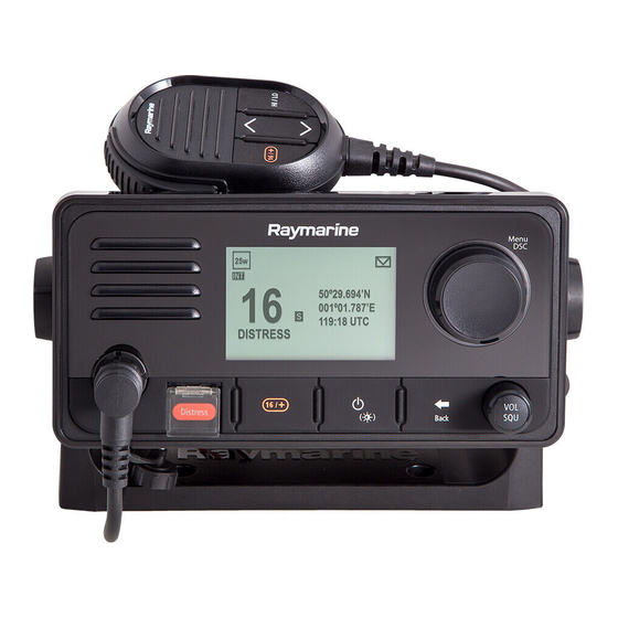
All images are provided for illustration purposes only. 2.2 Product overview The Ray53, Ray63 and Ray73 are 12 V dc, Class D Digital Selective Calling (DSC) VHF radios. DSC enables you to make a selective call to a specific radio, and to transmit and receive position information to and from the selected radio. -
Page 20: Applicable Products
• 1 Wired handset station and up to 2 Wireless handset stations E70517 Ray73 Same as Ray63 with additional: • Built-in AIS receiver • Loud hailer connection Required additional components Your product requires a VHF antenna. Part number... -
Page 21: Optional Wireless Components
Description A80540 Wireless hub Allows connection of up to 2 Wireless handsets. R70739 Wireless hub adaptor Allows Wireless hub connection to Ray63 / Ray73 radios. Wireless handset with inductive A80544 Wireless handset (including charging and wireless speaker holster) connection. A80543... -
Page 22: Incompatible Mfds
E-Series Widescreen C-Series Widescreen E-Series Classic G-Series Incompatible MFDs This product is NOT compatible with the following legacy Raymarine multifunction displays. Legacy MFDs C-Series Classic A-Series Classic 2.4 Software updates Raymarine periodically releases software updates for its products. These updates provide new features, current feature enhancements and bug fixes which improves product performance and usability. -
Page 23: Checking Software Versions
• Ensure that the unit has a reliable power supply and that the update process is not interrupted. • Damage caused by an incomplete update is not covered by Raymarine warranty. • By downloading the software update package, you agree to these terms. -
Page 25: Chapter 3 Licensing
Chapter 3: Licensing Chapter contents • 3.1 Licensing on page 26 • 3.2 Obtain MMSI (Maritime Mobile Service Identity) number on page 30 • 3.3 Automatic Transmitter Identification System (ATIS) on page 31 Licensing... -
Page 26: Licensing
3.1 Licensing Prior to using this product for the first time, please check your national requirements for both operator and equipment licensing. Important: It is your responsibility to determine whether a license is required in your area before operating this equipment. In many regions, the following authorizations are required from the relevant regulatory authority: Ship Station VHF license;... - Page 27 The following table lists the relevant issuing authority for licences in each region, along with a link to the relevant website. Many authorities allow you to apply for a license online. Country Code Regulatory authority Website Austria Austrian Regulatory Authority http://www.rtr.at for Broadcasting and Telecommunications...
-
Page 28: Rest Of World Licensing Requirements
Country Code Regulatory authority Website Poland Prezes Urzędu Komunikacji http://www.uke.gov.pl Elektronicznej Portugal Autoridade Nacional de https://www.anacom.pt Comunicações Romania National Authority for http://www.ancom.org.ro/en Management and Regulation in Communications of Romania Slovenia Agency for communication http://www.akos-rs.si/akos-ang networks and services of the Republic of Slovenia Slovakia Telecommunications Regulatory http://www.teleoff.gov.sk/in-... -
Page 29: Additional Information - Ray63
Additional information – Ray63 The following additional information is required for completing a license application in Canada and the US. ISED ID 4069B-RAY60D FCC ID PJ5–RAY60 FCC Type accepted Parts 2*, 15 and 80 Output power 1 watt (low) and 25 watt (high) -
Page 30: Additional Information - Wireless Hub
If an MMSI number is not entered, the DSC functionality of your radio will be disabled. In the United States of America, the MMSI and Static Data must be entered only by a Raymarine® dealer or other appropriately qualified installer of marine communications equipment on board vessels. -
Page 31: Automatic Transmitter Identification System (Atis)
You can only enter a MMSI number once, if you enter the number incorrectly or need to change your MMSI number, the unit will require re-programming by an authorized Raymarine dealer. 3.3 Automatic Transmitter Identification System (ATIS) Your product includes ATIS functionality for use on the inland waterways of contracting governments of the “Regional Arrangement on the Radiocommunication Service for Inland Waterways”... -
Page 33: Chapter 4 Parts Supplied
Chapter 4: Parts supplied Chapter contents • 4.1 Parts supplied – Ray53 on page 34 • 4.2 Parts supplied – Ray63 / Ray73 on page 35 Parts supplied... -
Page 34: Parts Supplied - Ray53
4.1 Parts supplied – Ray53 The parts listed below are supplied with the Ray53. Item Description VHF Radio Sun cover Panel mount gasket Mounting bracket (Trunnion) Mounting bracket knobs Fistmic hook plate 4 x M4x25 screws (For Bracket (Trunnion) mounting) Documentation 4 x M4 nuts, spring washers and M4x25 machine screws (For Panel mounting) Protective antenna boot... -
Page 35: Parts Supplied - Ray63 / Ray73
4.2 Parts supplied – Ray63 / Ray73 The parts listed below are supplied with the Ray63 and Ray73. Item Description VHF Radio Sun cover Panel mount gasket Fistmic Mounting bracket (Trunnion) Mounting bracket knobs Fistmic hook plate 4 x M4x25 screws (For Bracket (Trunnion) mounting) -
Page 37: Chapter 5 Product Dimensions
Chapter contents • 5.1 Product dimensions — Ray53 on page 38 • 5.2 Product dimensions — Ray63 / Ray73 on page 39 • 5.3 Product dimensions — Fistmic on page 40 • 5.4 Product dimensions - Wired handset (Raymic) on page 41 •... -
Page 38: Product Dimensions - Ray53
5.1 Product dimensions — Ray53 Panel mount dimensions 168 mm (6.6 in) 156 mm (6.1 in) 88.5 mm (3.5 in) 134 mm (5.3 in) 39.75 mm (1.6 in) 21.5 mm 0.85 in) 59 mm (2.3 in) 25 mm 1.0 in) 143.6 mm (5.7 in) Bracket mount dimensions 192.5 mm (7.6 in) -
Page 39: Product Dimensions - Ray63 / Ray73
5.2 Product dimensions — Ray63 / Ray73 Panel mount dimensions 199 mm (7.83 in) 98.5 mm (3.88 in) 143 mm (5.63 in) 61.6 mm (2.43 in) 16.6 mm (0.65 in) 90 mm 3.54 in) 176 mm (6.93 in) Bracket mount dimensions 226 mm (8.89 in) -
Page 40: Product Dimensions - Fistmic
5.3 Product dimensions — Fistmic 68.5 mm (2.7 in) 97.6 mm (3.8 in) 8 mm (0.3 in) 36 mm (1.4 in) The Fistmic’s fitted, coiled lead can be extended comfortably to approximately 1 meter (3.3 ft.) -
Page 41: Product Dimensions - Wired Handset (Raymic)
5.4 Product dimensions - Wired handset (Raymic) 167.34 mm (6.59 in) 151 mm (5.94 in) 66.9 mm (2.63 in) 70 mm (2.76 in) 46.7 mm (1.84 in) The Handset’s fitted, coiled lead can be extended comfortably to approximately 1 meter (3.3 ft.). Ensure sufficient space is available below the desired mounting area to accommodate the cable. -
Page 42: Product Dimensions - Speakers
5.5 Product dimensions - speakers The dimensions for the Passive and Active speakers are shown below. 118.5 mm (4.67 in) 112.5 mm (4.43 in) 18.3 mm (0.72 in) 26.4 mm (1.04 in) 25 mm (0.98 in) 30.6 mm (1.20 in) The Passive speaker includes a fitted 2 m (6.56 ft) audio cable terminated with a male RCA plug. -
Page 43: Product Dimensions - Wireless Hub
5.6 Product dimensions - Wireless hub The dimensions for the wireless hub are shown below. 26.7 mm (1.05 in) 68.04 mm (2.68 in) 32.16 mm (1.27 in) 70 mm (2.76 in) 109.2 mm (4.30 in) 121.6 mm (4.79 in) 6.2 mm (0.24 in) 87.72 mm (3.45 in) 29.14 mm (1.15 in) Min 106.95 mm (4.21 in) Max... -
Page 44: Product Dimensions - Wireless Handset And Holster
5.7 Product dimensions - Wireless handset and holster 173.33 mm (6.82 in) 50.5 mm (1.99 in) 71.41 mm (2.81 in) The charging holster is supplied with a fitted 2 meter (6.56 ft) power cable terminated with bare ended wires. -
Page 45: Chapter 6 Location Requirements
Chapter 6: Location requirements Chapter contents • 6.1 Selecting a location on page 46 • 6.2 EMC installation guidelines on page 48 • 6.3 Wireless product location requirements on page 49 Location requirements... -
Page 46: Selecting A Location
6.1 Selecting a location Warning: Potential ignition source This product is NOT approved for use in hazardous/flammable atmospheres. Do NOT install in a hazardous/flammable atmosphere (such as in an engine room or near fuel tanks). General location requirements When selecting a location for the unit it is important to consider a number of factors. To ensure optimum performance, it is recommended that the display is temporarily powered up and tested, at the chosen location, prior to installation. -
Page 47: Gnss (Gps) Location Requirements
• Ensure that any power cables for external equipment are not entangled with the power or data cables for these devices. • Consider fitting one or more high frequency suppression ferrites to the EMI-emitting device. The ferrite(s) should be rated to be effective in the range 100 MHz to 2.5 GHz, and should be fitted to the power cable and any other cables exiting the EMI-emitting device, as close as possible to the position where the cable exits the device. -
Page 48: External Gnss (Gps) Antenna Location Requirements
Ensure that your VHF antenna is connected to the radio before transmission. Raymarine® declares a Maximum Permissible Exposure (MPE) radius of 1.8 meters (5.9 ft.) for this system, assuming 25 watts output to an omnidirectional antenna of 3dBi gain or less. -
Page 49: Suppression Ferrites
Requirement for ferrites on non-Raymarine cables. If your product is to be connected to other equipment using a cable not supplied by Raymarine, a suppression ferrite MUST always be attached to the end of the cable nearest to the Raymarine product. -
Page 50: Pre-Installation Site Survey
Reflective surfaces such as metal surfaces, some types of glass and even mirrors can drastically affect performance or even block the wireless signal. Interference and other equipment Wireless products should be installed at least 1m (3 ft) away from: • Other wireless-enabled products. •... - Page 51 For reliable wireless performance the signal strength should be better than –75dBm, the closer the signal is to zero the better the wireless performance will be (e.g. –40dBm is better than –75dBm). 9. If the wireless channel your hub is using is congested with wireless signals then change your hub’s wireless channel (Menu >...
-
Page 53: Chapter 7 Installation
Chapter 7: Installation Chapter contents • 7.1 Mounting on page 54 Installation... -
Page 54: Mounting
7.1 Mounting Tools required for installation Power drill 2. Jigsaw for panel mount cut-out 3. Pozi-drive screwdriver 4. Adhesive tape 5. 7 mm (9/32”) Wrench (spanner) for bracket mounting fixings 6. File for panel mount cut out Hole saw for panel mounting (For hole saw size refer to your product’s mounting template) 8. -
Page 55: Mounting Options
Mounting options The product can be mounted in the following configurations. Bracket mount — Table top 2. Bracket mount — Overhead 3. Bracket mount — Bulkhead 4. Panel mount Bracket mounting Follow the steps below to mount the product on it’s bracket. Before mounting the unit ensure that you have: •... - Page 56 1. Mark the location of the bracket mounting holes on the mounting surface. 2. Drill holes for the mounting fixings using a drill with a suitable sized drill bit. 3. Use the fixings provided to attach the bracket securely to the mounting surface. 4.
-
Page 57: Panel Mounting - Ray53
Panel mounting — Ray53 Removing the mounting hole covers Before the radio can be panel mounted the mounting hole covers must be removed. 1. Using a flat blade screw driver, insert the tip of the screw driver in the slot between the back of the cover and the unit. - Page 58 1. Using a drill and a 4 mm (5/32) drill bit, drill out the 4 mounting holes. Holes should be drilled from the front of the unit, taking care not to apply too much force to the drill. Panel mounting To panel mount the radio follow the steps below.
- Page 59 1. Check the selected location for the unit. A clear, flat area with suitable clearance behind the panel is required. 2. Fix the supplied mounting template to the selected location, using masking or self-adhesive tape. 3. Using a suitable hole saw (the size is indicated on the template), make a hole in each corner of the cut-out area.
-
Page 60: Panel Mounting - Ray63 / Ray73
The gasket should always be used. It may also be necessary to use a marine-grade sealant if the mounting surface or binnacle is not entirely flat and stiff or has a rough surface finish. Panel mounting — Ray63 / Ray73 Drilling out the mounting holes Before panel mounting the Radio the mounting holes must be drilled out. - Page 61 1. Using a drill and a 4 mm (5/32) drill bit, drill out the 4 mounting holes. Holes should be drilled from the front of the unit, taking care not to damage the unit by applying too much force to the drill. Panel mounting To panel mount the Radio follow the steps below.
- Page 62 1. Check the selected location for the unit. A clear, flat area with suitable clearance behind the panel is required. 2. Fix the supplied mounting template to the selected location, using masking or self-adhesive tape. 3. Using a suitable hole saw (the size is indicated on the template), make a hole in each corner of the cut-out area.
-
Page 63: Fistmic Mounting
1. Orientate the bottom-right side of the bezel under the bottom-right side of the unit, ensuring that the clips along the bottom edge of the bezel latch into position. 2. Ensure the bezel is correctly aligned with the unit, as shown. 3. -
Page 64: Wired Handset Mounting Using The Holster
1. Check the selected location for the Hook plate, a clear flat area is required, with sufficient space around it to place and remove the Fistmic / Handset and coiled cable. 2. Using a pencil, offer up the Hook plate to the desired location and mark the location of the screw holes on the mounting surface. -
Page 65: Wired And Wireless Speaker Mounting
1. Check the selected location for the mounting holster, a clear flat area is required, with sufficient space around it to place and remove the handset. 2. Using a pencil, offer up the holster to the desired location and mark the location of the screw holes on the mounting surface. - Page 66 1. Remove the speaker’s bezel. 2. Using the supplied mounting template, mark the location of the cut out and fixing holes on the mounting surface. 3. Using a 89 mm (3 ½ in) hole saw, drill out the centre cut out area indicated on the mounting template.
-
Page 67: Pass-Through Panel Kit Mounting
Pass-through panel kit mounting When installing handsets, the pass-through panel kit should be used to secure the cable’s connector to the panel the cable has to pass through. Splash-proof dust cap with lanyard Mounting plate fixings x 3 Mounting plate nut Mounting plate Mounting plate gasket Extension cable... -
Page 68: Mounting The Wireless Hub
2. Ensuring correct orientation of the mounting plate, offer up the plate to the desired location and mark the location of the screw holes and the center hole on the mounting panel. To ensure that the handset’s connector points down when connected, orientate the mounting plate so that the lanyard grove is pointing straight up. - Page 69 1. Using the supplied mounting template, mark the location of the fixing holes on the mounting surface. 2. Drill holes for the mounting fixings using a drill with a suitable sized drill bit. 3. Screw the fixings approximately half way into the holes in the mounting surface. 4.
- Page 70 Antenna orientation Radio waves are emitted from the wireless hub perpendicular to the orientation of the hub’s antenna. Keeping the antenna vertical should provide the best coverage for devices on the same plane as your hub. Positioning the antenna horizontally will provide better coverage above and below the hub. Installing the wireless hub antenna extension accessory An extension cable accessory (A80541) is available for the wireless hub’s antenna.
-
Page 71: Mounting The Charging Holster For The Wireless Handset
2. Using a pencil, offer up the Mounting plate to the desired location and mark the location of the screw holes and the center hole on the mounting panel. 3. Drill holes for the mounting fixings using a drill with a suitable sized drill bit. 4. -
Page 73: Chapter 8 Cables And Connections
8.4 Power connection on page 77 • 8.5 Fistmic connection (Ray63 / Ray73 only) on page 82 • 8.6 Secondary handset station (Ray63 / Ray73 only) on page 83 • 8.7 SeaTalkng ® / NMEA 2000 connection on page 84 •... -
Page 74: General Cabling Guidance
• Unless otherwise stated only use cables supplied by Raymarine. • Where it is necessary to use non-Raymarine cables, ensure that they are of correct quality and gauge for their intended purpose. (e.g.: longer power cable runs may require larger wire gauges to minimize voltage drop along the run). -
Page 75: Cable Shielding
Connections to other equipment Requirement for ferrites on non-Raymarine cables If your Raymarine equipment is to be connected to other equipment using a cable not supplied by Raymarine, a suppression ferrite MUST always be attached to the cable near the Raymarine unit. -
Page 76: Connections Overview - Ray63 / Ray73
6. NMEA 0183 connection. Power supply connection. 8.3 Connections overview — Ray63 / Ray73 The following connections are available on the Ray63 and Ray73. Primary station (8 pin) connection. 2. Grounding point — DO NOT USE! 3. Second station (12 pin) connection. -
Page 77: Primary And Secondary Station Connectors
Primary and secondary station connectors The connectors below are used to connect the supplied Fistmic and / or the optional Wired (Raymic) handset to the Base station. Connector Description Connects to Primary station connector (8 pin • Fistmic (supplied) front Fistmic connector) Secondary station connector •... -
Page 78: In-Line Fuse And Thermal Breaker Ratings
7 A (if only connecting one device) Note: • The suitable fuse rating for the thermal breaker is dependent on the number of devices you are connecting. If in doubt consult an authorized Raymarine ® dealer. • Your product’s power cable may have a fitted in-line fuse. If not, add an in-line fuse to the positive wire of your product’s power connection. - Page 79 Implementation — connection to distribution panel (Recommended) Waterproof fuse holder containing a suitably-rated inline fuse must be fitted. For suitable fuse rating, refer to: In-line fuse and thermal breaker ratings. Product power cable. Drain wire connection point. • It is recommended that the supplied power cable is connected to a suitable breaker or switch on the vessel's distribution panel or factory-fitted power distribution point.
- Page 80 Important: Observe the recommended fuse / breaker ratings provided in the product’s documentation, however be aware that the suitable fuse / breaker rating is dependent on the number of devices being connected. Implementation — direct connection to battery • Where connection to a power distribution panel is not possible , the power cable supplied with your product may be connected directly to the vessel's battery, via a suitably rated fuse or breaker.
- Page 81 • Ensure that the extension cable is of a sufficient gauge for the supply voltage and the total load of the device and the length of the cable run. Refer to the following table for typical minimum power cable wire gauges. Cable length in meters (feet) Wire gauge in AWG (mm ) for...
-
Page 82: Fistmic Connection (Ray63 / Ray73 Only)
8.5 Fistmic connection (Ray63 / Ray73 only) Front connection The Fistmic can be connected directly to the front connector on your Radio. Rear connection Handset extension cable (A80291) 2. Fistmic adaptor cable (A80296) The Fistmic can also be connected to the Rear station connection using the appropriate adaptor... -
Page 83: Secondary Handset Station (Ray63 / Ray73 Only)
The Fistmic must NOT be used to create a second station, as the operator will not have access to all Radio functions or the information displayed on the Radio’s LCD screen. 8.6 Secondary handset station (Ray63 / Ray73 only) The Raymic handset accessory can be connected to the Secondary station connector located on the rear of the radio, this will create a second fully functional station. -
Page 84: Connecting Handsets And Cables
Connecting handsets and cables Follow the steps below to connect handsets and extension cables together. 1. If fitted, unscrew and remove the dust cap from the relevant connector. 2. Ensure the cable connectors are correctly orientated, before insertion. 3. Ensure connectors are fully inserted, before locking.. 4. -
Page 85: Nmea 0183 Connection
8.8 NMEA 0183 connection The NMEA 0183 wires can be used to connect the unit to a NMEA 0183 GNSS (GPS) receiver or MFD. Yellow = Receive positive (+) wire 2. Green = Receive negative (-) wire 3. White = Transmit positive (+) wire 4. -
Page 86: Connecting A Vhf Antenna
8.9 Connecting a VHF antenna The radio must be connected to a suitable VHF antenna (not supplied). The antenna connection must be protected so it cannot come into contact with any bare metal (which may be grounded). A protective boot is supplied that can be used to ensure isolation of the antenna connection. 1. -
Page 87: Gnss (Gps) Antenna Connection
8.10 GNSS (GPS) antenna connection You can improve the performance of your radio’s built-in GNSS (GPS) receiver using an external antenna. Follow the steps below to connect the external antenna: 1. Remove the dust cap from the external antenna connector on your radio. Ensuring correct connector orientation, fully insert the external antenna connector into the GA150’s connector. -
Page 88: Wireless Hub Connection
8.12 Wireless hub connection The Wireless hub connects to the second station connector on the rear of the Ray63 / Ray73 radios using the Wireless hub adaptor. The Wireless hub allows connection of wireless handset stations. Ray63 / Ray73 VHF radio. -
Page 89: In-Line Fuse And Thermal Breaker Ratings
Thermal breaker rating 2 A (refer to note below) Note: • The suitable fuse rating for the thermal breaker is dependent on the number of devices you are connecting. If in doubt consult an authorized Raymarine ® dealer. 8.14 Wireless handset connections The Wireless handset connects wirelessly to the Wireless hub, and the Wireless speaker connects wirelessly to the Wireless handset. -
Page 90: Wireless Speaker - Power Connection
2 A (refer to note below) Note: • The suitable fuse rating for the thermal breaker is dependent on the number of devices you are connecting. If in doubt consult an authorized Raymarine dealer. ® 8.16 Loud hailer connection (Ray73 only) - Page 91 Positive (+) hailer wire (Purple) Negative (-) hailer wire (Gray) Cables and connections...
-
Page 93: Chapter 9 Getting Started
9.17 Changing the radio region on page 112 • 9.18 Switching between high and low transmit power on page 113 • 9.19 GNSS (GPS) set up on page 113 • 9.20 Station priority (Ray63 and Ray73 only) on page 114 Getting started... -
Page 94: Licensing
9.1 Licensing Prior to using this product for the first time, please check your national requirements for both operator and equipment licensing. Important: It is your responsibility to determine whether a license is required in your area before operating this equipment. In many regions, the following authorizations are required from the relevant regulatory authority: Ship Station VHF license;... -
Page 95: Controls And Interface
9.3 Controls and interface The controls and interface available are as follows: Base station Built-in speaker 2. Rotary knob with center OK push button — Press knob in to access menu and DSC functions and to confirm selections. Turn rotary clockwise or anti-clockwise to move up and down through menu items or to change channel from the Homescreen. -
Page 96: Handset Controls
4. 16 / + — When powered on press to switch between priority channels. 5. HI/LO — Press to switch between High (25 W) and low (1 W) transmit power. 6. Channel Up / Channel Down — Changes the channel up or down. 9.4 Handset controls Overview of wireless handset controls. -
Page 97: Powering The Unit On
13. VOL/SQ — Press button to switch between volume and squelch controls. 9.5 Powering the unit on With the radio connected to a power supply the power button is used to switch the radio on and off. 1. Press the Power button to power-up the radio. The startup is displayed. -
Page 98: Powering The Handset
Powering the handset To power the Handset on and off follow the steps below. With the Base station powered On: 1. Press and hold the Power button, located on the top of the Handset, for 2 seconds. The Handset will power on. 2. -
Page 99: Status Bar Symbols
Status bar — The status bar displays symbols which indicate the current status of the unit. 2. Frequency band — Indicates which channel frequency band is in use: • USA — United States of America • INT — International • CAN — Canada •... - Page 100 Symbol Name Description Fog horn Indicates that the radio is in Fog horn mode. Transmit Indicates the radio is currently transmitting (e.g. the PTT button is being pressed.) Receive Indicates the radio is currently receiving a transmission Weather Indicates that the weather alerts mode is activated.
-
Page 101: Main Menu Overview
Symbol Name Description Power supply voltage too high Indicates the power supply to the radio is above the specified operating voltage. Indicates that a DSC call has been received GPS Fix Indicates if the radio has a GPS/GNSS fix. Main menu overview The main menu is accessed by Pressing the OK button from the Homescreen. - Page 102 3. Menu items The main menu includes the following items: Symbol Name Sub-options * DSC Calls • Individual call • Distress call • Position request • Group call • All ships call • Phonebook • Call logs • Test call •...
- Page 103 Symbol Name Sub-options • Hailer ** Hailer/Fog horn • Fog horn ** Intercom • Intercom • Display set-up Set-up • Language • Units • Power output • Sensitivity • Noise cancelling (Tx) • ** Wireless set-up • Handset name • Key beep •...
-
Page 104: Shortcut List
9.8 Shortcut list Pressing the Power button once while the radio is switched on will open the Shortcuts list. The Shortcuts list can be used to adjust the brightness, contrast and access frequently used functions. Frequently used functions can be added by selecting Add/edit shortcuts. Adjusting Brightness and Contrast The LCD Brightness (Backlight) and Contrast can be adjusted using the Shortcuts list. -
Page 105: Enabling Shared Brightness
Any adjustments to the shared brightness level will be applied to all products assigned to the same group. LightHouse™ / LightHouse™ 2 MFD Instrument display / Pilot controller VHF DSC Radio LightHouse™ 3 V3.4 or greater Multiple brightness groups can be configured. For example, these groups could be used to reflect the physical location of products on your vessel e.g.: helm and flybridge. -
Page 106: Initial Startup
9.10 Initial startup Unless your radio has been pre-programmed; the first time you power-up your radio you will be requested to select certain options. With the exception of your MMSI and ATIS ID, you will also be requested to enter these options after a factory reset. After acknowledging the startup screen, unless previously set you will be prompted to make the following selections: Language selection —... -
Page 107: Selecting A Language
9.12 Selecting a language The language the radio uses can be changed. From the Main menu: 1. Select Set-up. 2. Select Language. The languages available are: English (default) (default) — English • English English (default) • Español Español — Spanish Español •... -
Page 108: Entering Your Mmsi Number
9.15 Entering your MMSI number To program your radio with your MMSI number follow the steps below. From the Set-up menu: (Menu > Set-up) 1. Select DSC set-up. 2. Select MMSI. MMSI required required message will be displayed if no MMSI number has been set. The MMSI MMSI required... -
Page 109: Entering Your Atis Id
Caution: MMSI and ATIS ID entry You can only enter the MMSI number and ATIS ID once! If you store an incorrect MMSI number or ATIS ID in your product, it will have to be reset by an authorized Raymarine dealer. ®... - Page 110 From the Main menu. 1. Select Set-up. 2. Select ATIS set-up. 3. Select ATIS ID. Not set set will be displayed if no ATIS ID has been set. The first digit is set to a ‘9’ and cannot be changed, this is because all ATIS IDs start with a ‘9’. As most ATIS IDs consist of a ‘9’...
-
Page 111: Enabling And Disabling Atis Mode
Caution: MMSI and ATIS ID entry You can only enter the MMSI number and ATIS ID once! If you store an incorrect MMSI number or ATIS ID in your product, it will have to be reset by an authorized Raymarine ® dealer. -
Page 112: Changing The Radio Region
9.17 Changing the radio region Prior to using the radio you must set the Frequency band to the region your radio will be used in. From the Main menu: 1. Select Set-up. 2. Select Channel set-up. 3. Select Frequency band. 4. -
Page 113: Switching Between High And Low Transmit Power
If no position data is available then the latitude, longitude and time can be entered manually so that it can be included in DSC distress transmissions. Position data received from other vessels can be displayed on a connected Raymarine® multifunction display. -
Page 114: Selecting (Gnss) Gps Information To Display
4. Select OK to confirm the selection. 9.20 Station priority (Ray63 and Ray73 only) The Ray63 and Ray73 can have a Local Fistmic, connected to the front connector, and a Raymic (remote) handset, connected to the rear connector. The following rules apply to station priority: •... -
Page 115: Chapter 10 Wireless Handset Stations
Chapter 10: Wireless handset stations Chapter contents • 10.1 Wireless handsets on page 116 • 10.2 Connecting a wireless handset to the hub on page 117 • 10.3 Connecting the wireless speaker to the Wireless handset on page 119 • 10.4 Wireless set-up menu options on page 120 Wireless handset stations... -
Page 116: Wireless Handsets
(A80544) are required to create a wireless handset station. Additionally a Wireless speaker (A80543) can be connected to each Wireless handset. After connecting your Wireless hub to the Second station connector on the rear of your Ray63 / Ray73 Base station, the process for setting up a wireless handset station should be: Fully charge the Wireless handset. -
Page 117: Connecting A Wireless Handset To The Hub
With the handset powered off the battery symbol is displayed fullscreen. 10.2 Connecting a wireless handset to the hub Wireless handsets must be connected to the radio via a Wireless hub. When the Wireless handset is powered on for the first time you will need to connect it to a Wireless hub. -
Page 118: Checking The Wireless Hub's Password
Checking the Wireless hub's password You can check the Wireless hub’s password at anytime using a Wired handset. 1. Select Menu. 2. Select Set-up. 3. Select Wireless set-up. 4. Select Wireless hub set-up. 5. Select Password. The current password is displayed. Changing your wireless hub's password If desired you can change the Wireless hub’s default password using a Wired handset. -
Page 119: Connecting The Wireless Speaker To The Wireless Handset
Note: • While the name change is being applied the Wireless set-up menu will be unavailable. • Your Wireless handset will automatically reconnect to the hub using the new name. 10.3 Connecting the wireless speaker to the Wireless handset You can connect a Wireless speaker to your Wireless handset. 1. -
Page 120: Disconnecting A Wireless Speaker
Disconnecting a Wireless speaker To disconnect your Wireless speaker from the Wireless handset follow the steps below: With the speaker connected to the handset: 1. Press the Pairing button on the front of the speaker. 2. Once disconnected the speaker can be connected to any Wireless handset by following the 10.3 Connecting a wireless speaker to the wireless handset procedure. - Page 121 Menu item Description Options • Deutsch — German • Italiano — Italian Provides access to the Backlight • 1 to 9 Backlight level • Off Contrast Provides access to the Contrast • 1 to 10 level Key beep Enables adjustment of the •...
-
Page 123: Chapter 11 Digital Selective Calling (Dsc)
Chapter 11: Digital selective calling (DSC) Chapter contents • 11.1 Digital Selective Calling (DSC) on page 124 • 11.2 Distress calls on page 125 • 11.3 Urgency calls on page 130 • 11.4 Safety calls on page 130 • 11.5 Individual (routine) calls on page 131 •... -
Page 124: Digital Selective Calling (Dsc)
11.1 Digital Selective Calling (DSC) Traditional VHF radio systems require users to listen until someone speaks, and then determine whether the call is for them. DSC ensures that calls are received by alerting or announcing the intended recipient(s) first so they are ready to listen to the subsequent message on the relevant channel. -
Page 125: Distress Calls
Individual (routine) Routine calls are used for contacting other vessels, marinas, or shore stations. Routine calls are made on channel 70 using the dedicated Maritime Mobile Service Identity (MMSI) number of the station to be contacted, selecting a VHF working channel and sending the call. Both radios automatically switch to the chosen channel for conversation. -
Page 126: Making A Mayday Call
Once the DISTRESS DISTRESS DISTRESS button is pressed a 3 second count down will begin, when the count down reaches zero the DSC distress call is transmitted. The distress call is repeated automatically until it is acknowledged. 2. Press and hold the PTT button, then slowly and clearly speak the details of the distress in the following format: MAYDAY, MAYDAY, MAYDAY This is <state name of vessel 3 times>... -
Page 127: Cancelling A Distress Call After Transmission
Cancelling a distress call after transmission A distress call can be cancelled after it has been transmitted. 1. Select Options. 2. Select Cancel distress. 3. Select Yes to confirm cancellation. 4. Select OK. 5. Press and hold the PTT button and make a broadcast to all stations giving your vessel’s name, call sign and MMSI number and cancel the false distress alert Digital selective calling (DSC) -
Page 128: Receiving A Distress Call
Example: “All, Stations, All Stations, All Stations. This is <NAME>, <CALL SIGN>, <MMSI ID>, <POSITION>. Cancel my distress alert of <DATE>, <TIME>, <NAME>, <CALL SIGN>” 6. Repeat the broadcast described in step 5. Receiving a distress call It is expected that only a Coast Radio Station (CRS) will acknowledge DSC distress calls and will act as the coordinator for the rescue operation. -
Page 129: Ignoring A Distress Call
The details of the distress call are recorded in the distress log and the envelope icon will flash to let you know a message has been received. When connected to a Raymarine ® multifunction display (MFD) the position data from the distress call can also be displayed in the Chart application. -
Page 130: Urgency Calls
If a distress relay is sent specifically to the radio then it can be acknowledged, otherwise acknowledgement is not required. Acknowledging a distress relay sent to your vessel If a distress relay is specifically sent to your vessel this will be because the sender deems you to be in a position to assist in the rescue. -
Page 131: Receiving A Safety Call
2. Select the channel for subsequent communication. The call is transmitted. Once the call has been successfully transmitted ‘Sent’ is displayed onscreen and the channel is changed to the specified channel. 3. Press the OK button. 4. Press and hold the PTT button and speak the following message: SECURITE, SECURITE, SECURITE ALL STATIONS, ALL STATIONS, ALL STATIONS This is —... -
Page 132: Receiving An Individual Call
7. Press and hold the PTT button and speak your message. 8. Release the PTT button when you have completed your message. Receiving an Individual call With an incoming individual call displayed: 1. Select Show info from the options to review relevant call details. 2. -
Page 133: Position Requests
Position requests can be sent to any contact stored in the Phonebook or by manually inputting the station’s MMSI number. When connected to a Raymarine® multifunction display (MFD) the position data from the request can also be display in the Chart app. -
Page 134: Editing A Ponebook Entry
7. If the Contact name is less than 10 characters, press and hold the OK button and select Save. 8. Press the Back button at any time to edit characters you have already entered. 9. Press and hold the OK button and select Move cursor to edit an existing character. 10. -
Page 135: Test Calls
• Distress calls • Non-distress calls • Outgoing calls • Position log 3. Select a call and press the OK button to view details. 4. Select Options to view available options. • Call Back — return a received call. • Resend — only available in the outgoing call log. •... -
Page 136: Receiving A Test Call
Receiving a test call Your radio will automatically acknowledge received Test calls from other stations When a Test call is received a notification is displayed to alert you that a test call has been received and automatically acknowledged. 11.11 DSC set-up menu options The DSC set-up menu options can be accessed from the following menus: •... -
Page 137: Chapter 12 Vhf Operations
Chapter 12: VHF operations Chapter contents • 12.1 Watch modes on page 138 • 12.2 Scan Mode on page 138 • 12.3 Priority channels on page 138 • 12.4 Sensitivity on page 139 • 12.5 Private channels on page 139 •... -
Page 138: Watch Modes
12.1 Watch modes Watch mode monitors priority channels and the currently selected channel. There are 2 types of watch mode; Dual watch and Triple watch or Tri watch. • Dual watch — This mode monitors priority channel 16 and the currently selected channel. •... -
Page 139: Switching Between Priority Channels
Switching between priority channels 1. Press the 16 / + button to switch between priority channels. Setting a second priority channel You can select which channel you want to use as the second priority channel. From the Channel set-up menu: Menu > Set-up > Channel set-up. 1. -
Page 140: Automatic Transmitter Identification System (Atis) And Marcom-C Mode
12.7 AIS receiver Depending on variant your radio may have a built-in AIS receiver. With the built-in AIS receiver switched on AIS information can be sent to a connected Raymarine® MFD using either NMEA 0183 or SeaTalkng ®. Note: If using the built-in AIS receiver and outputting over NMEA 0183, ensure that the baud rate is set to 0183 High speed: Menu >... -
Page 141: Set-Up Menu Options
• Wireless hub set-up which apply to wireless devices. • Wireless hub Note: • Wireless speaker Menu only available on Ray63 and Ray73 when a Wireless hub is connected. Key Beep Enables adjustment of the beep • Off which is heard when pressing •... -
Page 142: Display Set-Up Menu
Menu Description Options GPS set-up Provides access to the GPS • Internal GPS set-up menu. • Homescreen display • Bearing mode • Position requests • Set manual position DSC set-up Provides access to the DSC • MMSI set-up menu. • Auto channel change •... - Page 143 Menu Description Options • Flybridge • Mast • Group 1 to Group 5 VHF operations...
-
Page 145: Chapter 13 Hailer, Fog Horn, And Intercom
Chapter 13: Hailer, Fog horn, and Intercom Chapter contents • 13.1 Hailer Fog Intercom menu on page 146 • 13.2 Loud hailer on page 146 • 13.3 Fog horn on page 146 • 13.4 Intercom on page 147 Hailer, Fog horn, and Intercom... -
Page 146: Hailer Fog Intercom Menu
13.1 Hailer Fog Intercom menu The menu options available are determined by the accessories connected to your radio. Menu name Connected devices Hail/Fog/Int Loud hailer and second station connected. Loud hailer connected, no second station Hailer/Fog Intercom Second station connected, no loud hailer Note: For simplicity the procedures in this section all refer to the Hail/Fog/Int menu. -
Page 147: Using The Fog Horn In Manual Mode
Fog mode Description Pattern At anchor Vessel is at anchor 12 consecutive rings Aground Vessel is aground 3 short rings, 12 consecutive rings, 3 short rings Using the fog horn in manual mode From the Hail/Fog/Int menu: Menu > Hail/Fog/Int. 1. -
Page 149: Chapter 14 Maintenance
Chapter 14: Maintenance Chapter contents • 14.1 Maintenance on page 150 Maintenance... -
Page 150: Maintenance
14.1 Maintenance This product has no user serviceable parts or adjustments. Never remove the cover or attempt to service the product, doing so may invalidate your product warranty. To following preventive measures should be followed: • Although the product is waterproof, keep the unit as dry as possible. •... -
Page 151: Chapter 15 Troubleshooting
15.5 DSC troubleshooting on page 158 • 15.6 AIS troubleshooting (Ray70 / 73 / 91 only) on page 159 • 15.7 Wired handset troubleshooting on page 160 • 15.8 Wireless troubleshooting (Ray63 / 73 / 90 / 91 only) on page 161 Troubleshooting... -
Page 152: Troubleshooting
If after referring to this section you are still having problems with your product, please refer to the Technical support section of this manual for useful links and Raymarine Product Support contact details. -
Page 153: Power Up Troubleshooting
Raymarine website: www.raymarine.com/software If you have a handset in your system (Ray63 / 73 / 90 / 91 only) with old software, you might need to put it into programming mode in order to update the software along with the radio. - Page 154 Possible causes Possible solutions backlight will start flashing. This means that the handset is now in programming mode. Follow the update instructions provided on the software download web page.
-
Page 155: Audio Troubleshooting (Transmission / Reception)
15.3 Audio troubleshooting (transmission / reception) Problems with your VHF radio and their possible causes and solutions are described below: No audio transmission Possible Causes Possible Solutions Incorrect settings Reset the radio to factory defaults, using the Maintenance menu: Menu > Set-up > Maintenance > System reset. Dirt or debris blocking the microphone Check the microphone on the fist mic or Raymic to ensure on the fist mic or Raymic handset. -
Page 156: Passive Speaker Troubleshooting
Passive speaker troubleshooting Passive speaker no alarm audio Possible Causes Possible Solutions Passive speaker connected to second Alarm audio is not available on passive speakers station connector. connected to the second station connector. Alarm audio should still be heard via the second station handset. -
Page 157: Gnss (Gps) Troubleshooting
15.4 GNSS (GPS) troubleshooting Problems with the GNSS (GPS) and their possible causes and solutions are described below. Before troubleshooting GNSS (GPS) problems, ensure your product has the latest software, by checking the Software Updates page on the Raymarine website www.raymarine.com/software No fix... -
Page 158: Dsc Troubleshooting
If an MMSI number is not entered, the DSC functionality of your radio will be disabled. In the United States of America, the MMSI and Static Data must be entered only by a Raymarine® dealer or other appropriately qualified installer of marine communications equipment on board vessels. -
Page 159: Ais Troubleshooting (Ray70 / 73 / 91 Only)
15.6 AIS troubleshooting (Ray70 / 73 / 91 only) AIS functions are not available / working (Ray70 / Ray73 / Ray91 only) Possible Causes Possible Solutions MMSI number not programmed. Programme your MMSI number. Each VHF radio requires a unique MMSI number. In the United States, this MUST be programmed into the unit by an authorized dealer. -
Page 160: Wired Handset Troubleshooting
Software Base station / Handset The Handset and Base station must both be running compatible software, refer to the Raymarine website for details of compatible mismatch software versions: www.raymarine.com/software. Poor / damaged / insecure Check that the Base station radio is correctly powered. -
Page 161: Wireless Troubleshooting (Ray63 / 73 / 90 / 91 Only)
15.8 Wireless troubleshooting (Ray63 / 73 / 90 / 91 only) Before troubleshooting problems with your wireless connection, ensure that you have followed the Wireless location requirements guidance provided in the relevant installation instructions and performed a power cycle/reboot of the devices you are experiencing problems with. - Page 162 Maintenance > About this unit. To obtain information on compatible software versions and also to obtain the latest software, visit the Raymarine website: www.raymarine.com/software It may be possible that the device has become Try updating software to a later version, or defective.
-
Page 163: Led Diagnostics - Wireless (Active) Speaker
LED diagnostics - Wireless (Active) speaker Sequence Color Status Purple Powering on Red and Blue Ready to pair/connect Paired ok Connected, no audio Purple Connected, audio active Powered on, not connected Troubleshooting... -
Page 165: Chapter 16 Technical Support
Chapter 16: Technical support Chapter contents • 16.1 Raymarine product support and servicing on page 166 • 16.2 Viewing product information on page 167 • 16.3 Learning resources on page 167 Technical support... -
Page 166: Raymarine Product Support And Servicing
You can obtain this product information using diagnostic pages of the connected MFD. Servicing and warranty Raymarine offers dedicated service departments for warranty, service, and repairs. Don’t forget to visit the Raymarine website to register your product for extended warranty benefits: http://www.raymarine.co.uk/display/?id=788. United Kingdom (UK), EMEA, and Asia Pacific: •... -
Page 167: Viewing Product Information
Alternatively product information can also be displayed by selecting About this unit from the Maintenance menu: Menu > Set-up > Maintenance. 16.3 Learning resources Raymarine has produced a range of learning resources to help you get the most out of your products. Video tutorials Raymarine official channel on YouTube: •... - Page 168 Technical support forum You can use the Technical support forum to ask a technical question about a Raymarine product or to find out how other customers are using their Raymarine equipment. The resource is regularly updated with contributions from Raymarine customers and staff: •...
-
Page 169: Chapter 17 Technical Specification
Chapter contents • 17.1 Technical specification — Ray53 on page 170 • 17.2 Technical specification — Ray63 on page 171 • 17.3 Technical specification — Ray73 on page 173 • 17.4 Technical specification — Wired handset (Raymic) on page 175 •... -
Page 170: Technical Specification - Ray53
17.1 Technical specification — Ray53 Environmental specification Operating temperature -20ºC (-4ºF) to +60ºC (140ºF) Storage temperature -25ºC (-13ºF) to +70ºC (158ºF) Relative humidity Water proofing IPx6 & IPx7 Connections • 1 x NMEA 0183 • 1 x SeaTalkng ® / NMEA 2000 •... -
Page 171: Technical Specification - Ray63
Automatic Signal Acquisition Almanac Update Automatic Geodetic Datum WGS-84 (alternatives available through Raymarine MFD) Refresh Rate 10 Hz (10 times per second Concurrent GNSS) Antenna • Internal — Ceramic chip mounted near top of unit • External — Passive antenna connection via TNC connector Position Accuracy •... - Page 172 Power specification Nominal supply voltage 12 V dc (Reverse polarity and over voltage protection) Operating voltage range 9 V dc to 16 V dc Current consumption • Less than 6 A at high power (13.6 V) • Standby: 600 mA •...
-
Page 173: Technical Specification - Ray73
Automatic Signal Acquisition Almanac Update Automatic Geodetic Datum WGS-84 (alternatives available through Raymarine MFD) Refresh Rate 10 Hz (10 times per second Concurrent GNSS) Antenna • Internal — Ceramic chip mounted near top of unit • External — Passive antenna connection via TNC connector Position Accuracy •... - Page 174 Transmitter Channels All available US, International and Canadian VHF marine bands Frequency Range 156.000 MHz to 157.425 MHz / 155.500 MHz to 161.425 MHz (Private channels) Frequency stability +/- 1.5 ppm Channel Spacing 25 kHz Power Output • Low power setting — 1 W •...
-
Page 175: Technical Specification - Wired Handset (Raymic)
Max speaker power output 5 W (8 Ω) Connection RCA female connector, connects to Wired handset via adaptor cable (A80297) VHF radio compatibility • Ray90 / Ray91 • Ray53 / Ray63 / Ray73 • Ray50 /Ray52 / Ray60 / Ray70 Technical specification... -
Page 176: Technical Specification - Wireless Hub
• x 1 Wireless hub connection via 2.4GHz wireless connection • x 1 Wireless (Active) speaker via 2.4GHz wireless connection VHF radio compatibility • Ray90 / Ray91 • Ray63 / Ray73 Battery Battery type Rechargeable Lithium ion Replaceable Capacity 2000 mAh... -
Page 177: Technical Specification - Wireless (Active) Speaker
Storage temperature -25ºC (-13ºF) to +70ºC (158ºF) Relative humidity Water proofing IPx6 & IPx7 Connections Connection x 1 Wireless handset connection via 2.4GHz Wireless connection VHF radio compatibility (via wireless • Ray90 / Ray91 hub) • Ray63 / Ray73 Technical specification... -
Page 179: Chapter 18 Spares And Accessories
Chapter 18: Spares and accessories Chapter contents • 18.1 Accessories on page 180 • 18.2 Ray53 / Ray63 / Ray73 spares on page 180 • 18.3 SeaTalkng ® cables and accessories on page 181 Spares and accessories... -
Page 180: Accessories
Wireless hub antenna extension 5m (16.4 ft) A80543 Wireless active speaker Wireless handset including charging holster A80544 R70739 Wireless hub adaptor for Ray63/Ray73 18.2 Ray53 / Ray63 / Ray73 spares The following spares are available: R70616 Wireless handset R70617 Wireless handset charging holster R70618... -
Page 181: Seatalkng ® Cables And Accessories
18.3 SeaTalkng ® cables and accessories SeaTalkng ® cables and accessories for use with compatible products. Part Number Description Details Includes: T70134 Starter kit • 1 x 5 Way connector (A06064) • 2 x Backbone terminator (A06031) • 1 x 3 m (9.8 ft) spur cable (A06040) •... - Page 182 Part Number Description Details A06047 SeaTalk (3 pin) to SeaTalkng ® adaptor cable 0.4 m (1.3 ft) A22164 SeaTalk to SeaTalkng ® spur cable 1 m (3.3 ft) A06048 SeaTalk2 (5 pin) to SeaTalkng ® adaptor cable 0.4 m (1.3 ft) A06045 SeaTalkng ®...
-
Page 183: Appendix A Nmea 0183 Sentences
Appendix A NMEA 0183 sentences The radio supports the following NMEA 0183 sentences. Ray53 / Ray63 Ray73 Sentence Description Receive Transmit Receive Transmit ● ● Digital Selective Calling ● ● Expanded Digital Selective Calling ● AIS VHF Data Link Message ●... -
Page 184: Appendix B Nmea 2000 Pgn List
Appendix B NMEA 2000 PGN list The radio supports the following NMEA 2000 PGNs. These are applicable to NMEA 2000 and SeaTalkng ® protocols. Ray53 / Ray63 Ray73 Description Receive Transmit Receive Transmit ● ● ● ● 59392 ISO Request ●... - Page 185 Ray53 / Ray63 Ray73 Description Receive Transmit Receive Transmit ● 129809 AIS Class B “CS” Static Data Report, Part A ● 129810 AIS Class B “CS” Static Data Report, Part B NMEA 2000 PGN list...
-
Page 186: Appendix C Mmsi Regulatory Bodies And Application Submissions
Appendix C MMSI Regulatory bodies and application submissions Country Regulatory Body Website links Ofcom http://www.ofcom.org.uk FCC (www.fcc.gov) • www.boatus.com • www.seatow.com • www.usps4mmsi.com www.ic.gc.ca Canada Industry Canada Australia Australian Maritime Safety http://www.amsa.gov.au/mmsi/ Authority (AMSA) Holland Agentschap Telecom www.agentschaptelecom.nl Belgium Belgisch Instituut www.bipt.be voor Postdiensten en Telecommunicatie... -
Page 187: Appendix D Vhf Channels
Appendix D VHF Channels International Marine VHF Channels and Frequencies Single RX Freq Freq CH No. TX Freq (MHz) (MHz) 156.050 160.650 Public correspondence, Port operations and Ship movement. 156.100 160.700 Public correspondence, Port operations and Ship movement. 156.150 160.750 Public correspondence, Port operations and Ship movement. - Page 188 Single RX Freq Freq CH No. TX Freq (MHz) (MHz) 1024 157.200 157.200 For future use 2024 161.800 161.800 For future use 157.250 161.850 Public correspondence, Port operations and Ship movement. Available for VDSMS 1025 157.250 157.250 For future use 2025 161.850 161.850...
- Page 189 Single RX Freq Freq CH No. TX Freq (MHz) (MHz) 2078 161.525 161.525 Port operations and Ship movement. Channel is limited to coast stations only unless otherwise permitted by UK regulation. 156.975 161.575 Public correspondence, Port operations and Ship movement. 1079 156.975 156.975...
- Page 190 Note: Channel 06 may also be used for communications between ship stations and aircraft engaged in coordinated search and rescue operations. Ship stations should avoid harmful interference to such communications on channel 06 as well as to communications between aircraft stations, ice breakers and assisted ships during ice seasons.
- Page 191 (New) (Old) TX Freq Freq Single CH No. CH No. (MHz) (MHz) Freq 156.300 156.30 Intership Safety. 1007 156.350 156.35 Commercial. VDSMS. 156.400 156.40 Commercial (Intership only). VDSMS. 156.450 156.45 Boater calling. Commercial and Non-commercial. VDSMS. 156.500 156.50 Commercial. VDSMS. 156.550 156.55 Commercial.
- Page 192 (New) (Old) TX Freq Freq Single CH No. CH No. (MHz) (MHz) Freq 156.375 x 156.375 Commercial. Used for bridge-to-bridge communications in lower Mississippi river (Intership only). 156.425 156.425 x Non-commercial. VDSMS. 156.475 x 156.475 Non-commercial. VDSMS. 156.575 x 156.575 Non-commercial.
- Page 193 Note: Four digit channels indicate simplex use of the ship station transmit side of an international semi-duplex channel. Operations are different from that of international operations on that channel. 2. Channel 13 should be used to contact a ship when there is danger of collision. All ships of length 20 metres or greater are required to guard VHF channel 13, in addition to VHF channel 16, when operating within US territorial waters.
- Page 194 (New) (Old) Areas Freq Freq Single of op- (MHz) (MHz) Freq eration 156.30 156.30 Intership, Commercial, Non-Commercial and areas Safety Maybe used for search and rescue communications between ships and aircraft. 1007 156.35 156.35 Intership, Ship/Shore and Commercial. BCC, GL, NL, INLD BC, WC 156.40...
- Page 195 (New) (Old) Areas Freq Freq Single of op- (MHz) (MHz) Freq eration 1018 156.90 156.90 Intership, Ship/Shore and Commercial. BCC, Towing — BCC area. GL, NL, INLD BC, WC 1019 156.95 156.95 Intership and Ship/Shore. areas DFO / Canadian Coast Guard. Pacific Pilots — BCC area.
- Page 196 (New) (Old) Areas Freq Freq Single of op- (MHz) (MHz) Freq eration 1063 156.175 156.17 Intership, Ship/Shore and Commercial. Tow boats — BCC area. 156.22 160.82 Ship/Shore and Public correspondence. 1064 156.22 156.22 Intership, Ship/Shore and Commercial Commercial fishing only. 1065 156.27 156.27...
- Page 197 (New) (Old) Areas Freq Freq Single of op- (MHz) (MHz) Freq eration 156.77 156.77 Intership, Ship/Shore, Commercial and Ship areas movement. Simplex port operation, ship movement and navigation related communication only. 1 watt maximum power. 156.82 156.82 Intership, Ship/Shore, Commercial and Ship areas movement.
- Page 198 • BCC — British Columbia Coast (Pacific Coast). • EC — East Coast: includes NL, AC, GL and Eastern Arctic areas. • GL — Great Lakes: includes St. Lawrence above Montreal. • NL — Newfoundland and Labrador. • WC — West Coast: includes BCC, Western Arctic and Athabasca-Mackenzie Watershed areas. •...
-
Page 199: Appendix E Phonetic Alphabet
Appendix E Phonetic alphabet To help make call letters more clearly understood, and to assist in spelling out similar sounding or unfamiliar word, radiotelephone users employ the international phonetic alphabet. ALPHA NOVEMBER BRAVO OSCAR CHARLIE PAPA DELTA QUEBEC ECHO ROMEO FOXTROT SIERRA GOLF... -
Page 200: Appendix F Prowords
Appendix F Prowords Prowords can be used to simplify and speed up radio communications. Proword Meaning ACKNOWLEDGE Have you received and understood? CONFIRM Is that correct? CORRECTION An error has been made? I SAY AGAIN I repeat (e.g. important information). I SPELL Phonetically spelling of the word. - Page 203 Integrated ............113 Passive speaker........... 87 Internal..............113 Primary station ............. 77 No position data ..........113 Ray53..............75 Position information ..........114 Ray63..............76 set-up..............113 Ray73 ..............76 GPS, See GNSS Raymic handset ...........83 Group call .............. 132 SeaTalkng ............84 Making ...............
- Page 204 Homescreen ............98 Options ..............55 Panel ..............57, 60 Pass-through panel kit ......... 67 Product holes..........57, 60 Ray53..............57 Individual call............125 Ray63..............60 Making ..............131 Ray73 ..............60 Reason codes ............. 131 Raymic ..............64 Receiving ............132 Wired handset............65 Installation Wired speaker .............66...
- Page 205 Urgency call............124 Safety call .............. 124 Making ............... 130 Making ............... 130 Receiving ............131 Receiving ............130 Scan mode ............138 Setting..............138 SeaTalkng Connecting ............84 VHF antenna ............20 Connecting cables ..........84 VHF channels SeaTalkng cables ........... 181 Canada ..............
- Page 208 Raymarine Marine House, Cartwright Drive, Fareham, Hampshire. PO15 5RJ. United Kingdom. Tel: +44 (0)1329 246 700 www.raymarine.com a brand by...