Table of Contents
Advertisement
Advertisement
Table of Contents

Related Manuals for Raymarine Ray230


Summary of Contents for Raymarine Ray230
- Page 1 Ray230 Ray230e Modular VHF Radio O w n e r ' s H a n d b o o k...
- Page 2 RAY230 & RAY230E Modular VHF Radio Owner’s Handbook Document number: R49006_2 Date: December 2001...
-
Page 4: Ray230 Us Version
Purpose This handbook contains very important information on the installation, operation, and maintenance of your RAY230 US version or RAY230E European version VHF radio. To get the best results in operation and performance, please take the time to read this handbook thoroughly. - Page 5 FCC when you apply for a Station License. If your vessel does not require a license, you may obtain an MMSI by contacting either BoatUS (www.boatus.com) or MariTEL (www.maritelusa.com). Once obtained, you can program the MMSI number into your RAY230 using the Menu Operation described in this handbook. INDUSTRY CANADA...
-
Page 6: Ray230E European Version
MMSI number into your RAY230E using the Menu Operation described in this handbook. If regulations in your area do not permit you to program the MMSI number yourself, your Raymarine dealer can program the number for you. - Page 7 Your Raymarine VHF radio generates and radiates radio frequency (RF) electromagnetic energy (EME). This equipment must be installed and operated in accordance with the instructions contained in this handbook. Failure to do so can result in personal injury and/or product malfunction.
- Page 8 Certificate No. RT008 Anchorage Park Portsmouth Hampshire England P03 5TD Raymarine RAY 230E VHF Radio with Class "D" DSC E43008 (Telular Interface Version) E43014 (Without Telular Interface Version) EN 60945 : 1997 EN 60945 : 1997 EN 301 025 Part 2 and Part 3...
-
Page 9: Table Of Contents
Setting the Volume ... 3-14 3.5.3 Setting the Squelch ... 3-14 3.5.4 Using the Function Key ... 3-14 3.5.5 Setting the Frequency Mode (RAY230) ... 3-15 3.5.6 Setting the Frequency Mode (RAY230E) ... 3-16 3.5.7 Receiving the Weather Channels ... 3-16 3.5.8 Selecting the Channel ... - Page 10 3.5.30.3.2 Manual Entry of Latitude/Longitude (L/L ENT) ... 3-56 3.5.30.3.3 Modifying the MMSI Number List (PHNBOOK) ... 3-58 3.5.30.3.4 Modifying the MMSI Group Number List (GROUP) ... 3-63 3.5.30.4 Setting Operation (RAY230) ... 3-65 3.5.30.4.1 Intercom Set Up ... 3-65...
- Page 11 3.5.30.5.4 Tri-Watch Set Up ... 3-75 3.5.30.5.5 ATIS On/Off Set Up ... 3-76 3.5.30.5.6 Siren Set Up ... 3-76 Section 4 Maintenance 4.1 How to Contact Raymarine ... 4-1 4.2 Preventative Maintenance ... 4-3 4.3 Specifications ... 4-3 4.4 Drawings ... 4-7 Section 5 Appendix 5.1 FCC Licensing Requirements ...
- Page 12 Glossary of Terms All Scan ... Scans all channels ATIS ... Automatic Transmission Identification Canadian Channels ... Channel designator as defined by Industry Carrier Wave ... A Radio Frequency on which intelligence is DSC ... Digital Selective Calling Dual Watch ... Monitor channel 16 while working on another Duplex ...
-
Page 14: General Description
General Description Section 1 General Description Introduction Congratulations on your purchase of Raymarine’s RAY230 US version or RAY230E European version fixed-mount marine radiotelephone. In this document, the terms “RAY230/E” and “RAY230/RAY230E” refer to both versions of the radiotelephone. The RAY230/RAY230E is a microprocessor controlled, digitally synthesized, compact transceiver that provides reliable simplex and semi- duplex (two-frequency) communications. - Page 15 Exclusive Features of the RAY230 US Version • Built-in DSC in accordance with standard SC-101 • Exclusive circuit that automatically selects 16 or 9 as the Priority Channel when the radio is turned on • Dedicated key for changing the Priority Channel (16/9) •...
-
Page 16: Installation
The original packing material should be used in the unlikely event it is necessary to return the unit to the factory. Equipment Supplied The following is a list of materials supplied with the RAY230 and RAY230E: Description Description... -
Page 17: Planning The Installation
Planning the Installation When planning the installation of your RAY230/E, the following conditions should be considered to ensure dependable and trouble-free operation. Mount the Base Station Transceiver, Handset cradle(s), and External Speaker(s) using the Mounting Templates provided. The Base Station Transceiver is designed to be mounted horizontally or vertically on a flat bulkhead below decks. - Page 18 Installation Base Station Transceiver 67 (2.63) External Speaker Unit 65 (2.56) 70 (2.76) 114 (4.49) Figure 2-2 Outline and Mounting Dimensions All dimensions are shown in millimeters and (inches) 197 (7.76) 200 (7.87) 228 (8.98) Cradle Unit...
-
Page 19: Electrical Connections
Electrical Connections 2.4.1 DC Power and Hailer/NMEA Cable Connections The 6-foot-long power cable is a multipurpose assembly containing three wire-pairs for connections to DC power, NMEA input, and the Hailer Horn speaker. Connections to the 6-pin connector are as follows: Wire Color Wire Color Function... -
Page 20: Hailer Cable Connections
Installation Figure 2-4 Power Cable Length Your RAY230/E radio should be connected to the nearest primary source of ship's DC power. A typical source may be a circuit breaker on the power panel or a fuse block near the unit. When connecting to either of these sources, the circuit breaker or other in-line fuse should be rated at 10 amps. -
Page 21: Nmea Data
Figure 2-5 Sample GPS Connections to NMEA 2.4.4 Using the SeaTalk Auxiliary Junction Box If installed, it may be convenient to connect the RAY230/E using the SeaTalk auxiliary junction box. This junction box enables the SeaTalk bus, power, and GPS to be connected. -
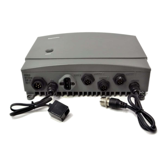
Page 22: Antenna Connections
Figure 2-6 SeaTalk Junction Box Connections 2.4.5 Antenna Connections Your coaxial VHF antenna cable connects to the RAY230/E antenna cable on the rear panel using a PL259 VHF type connector. Your VHF antenna cable can be cut to length but the overall cable length can be critical to performance. -
Page 23: Antenna Mounting Suggestions
2.4.6 Antenna Mounting Suggestions The best radio in the world is useless without a quality antenna and good location. Mounting the VHF antenna properly is very important because it will directly affect the performance of your VHF radio. A VHF antenna designed for marine vessels should be used. -
Page 24: Operations
Section 3 Operations Introduction The RAY230 has the capability to transmit and receive on all available US, Canadian, and International Marine VHF radiotelephone channels. The RAY230E can transmit and receive on all available International and US Marine VHF radiotelephone channels. There are channels that are FCC approved but may only be used by authorized stations for specific purposes, depending on the type of vessel (commercial or non-commercial.) -
Page 25: Control And Lcd Display
You can program the MMSI number yourself one time only using the Menu Operation described in section 3.5.30.4.2 or you can have your Raymarine dealer program the number for you. ALL SHIP key Switches to the All Ships Call mode for Safety and Urgency transmissions. - Page 26 DTMF interface (RAYCOM Cellular, Mini-M, etc.) connected to the AUX port at the rear of the transceiver. See section 3.5.19. 4/INT key (RAY230 only) This key inputs the number 4. When an alphanumeric response is appropriate, each press of this key alternately inputs the characters 4, G, H, then I.
- Page 27 Operations 5 key (RAY230 only) This key inputs the number 5. When an alphanumeric response is appropriate, each press of this key alternately inputs the characters 5, J, K, then L. 5/PRIV key (RAY230E only) This key inputs the number 5. When an alphanumeric response is appropriate, each press of this key alternately inputs the characters 5, J, K, then L.
- Page 28 Operations 9/ 1/25 key This key inputs the number 9. When an alphanumeric response is appropriate, each press of this key alternately inputs the characters 9, W, X, Y, and then Z. Pressing the FUNC key followed by the 9/1/25 key alternates the transmission power between 1W and 25W.
-
Page 29: Lcd Display
Pressing and holding this switch for 4 seconds selects Distress Signal Call mode. Subsequent operations are described in section 3.5.26.7. 3.2.2 LCD Display The following describes the functional characters on the RAY230/RAY230E Handset's LCD. Figure 3-2 LCD Display Layout NMEA indicator Displayed when the radio receives valid SeaTalk or NMEA position data. - Page 30 US frequency mode, if this feature has been activated. TX indicator Displayed while transmitting. CAN indicator (RAY230 only) Displayed when the Canadian frequency group is selected. US indicator Displayed when the US frequency group is selected.
-
Page 31: Radio Functions
Channel selection is available from among three frequency groups: US, International, or Canadian. Receiving the Weather Channels The RAY230 is programmed to receive 10 NOAA weather channels and will sound an alarm if a Weather Alert is received. Selecting the Priority Channel Select Channel 16 or Channel 9 as the Priority Channel. -
Page 32: Ray230E European Version
Position data from other Raymarine equipment is obtained using the SeaTalk line. 11. Remote Operation Up to three full function handsets can be connected to the RAY230. Auxiliary handsets can be housed in the cradle, enabling you to listen to radio reception from the external speaker. - Page 33 You can program the MMSI number yourself one time only using the Menu Operation described in section 3.5.30.4.2 or you can have your Raymarine dealer program the number for you. 12. NMEA Receiving Operation Positional information from external equipment is obtained using the NMEA 0183 interface.
- Page 34 This radio is also equipped with “ATIS Killer” to squelch unwanted electrical noise associated with ATIS transmissions. 14. SeaTalk Operation Position data from other Raymarine equipment is obtained using the SeaTalk line. 15. Remote Operation Up to three full function handsets can be connected to the RAY230E.
-
Page 35: Equipment Connections
3-12 Equipment Connections Note: Before the radio can recognize that a handset has been plugged into any of the three HANDSET ports, you must cycle the base station OFF and ON again, even if only moving the handset from one port to another. Operations... -
Page 36: Operating Procedures
RAY230E) from one handset will fully power ON the system and all handsets. To power off the RAY230/E: 1. Press the FUNC key followed by the 16/9/POWER key (RAY230) or 16/ POWER key (RAY230E) on any handset. The main unit and all handset(s) return to the standby condition. -
Page 37: Setting The Volume
3-14 Operations 3.5.2 Setting the Volume Setting the Volume on the Handset The sound volume adjustment for the handset has 11 settings. Pressing and releasing the VOL UP key increases the volume by one level; pressing and releasing the VOL DOWN key reduces the volume by one level. -
Page 38: Setting The Frequency Mode (Ray230)
3-15 Operations 3.5.5 Setting the Frequency Mode (RAY230) Select the channel frequency group to be used: US, International, or Canadian. Indicators displayed in the LCD identify the active frequency group: US for the US frequency group, INT for the International group, and CAN for the Canadian group. -
Page 39: Setting The Frequency Mode (Ray230E)
3-16 Operations 3.5.6 Setting the Frequency Mode (RAY 230E) Select the channel frequency group to be used from either US or International. Indicators displayed in the LCD identify the active frequency group: US for the US frequency group or INT for the International group. Note: Access to the US frequency group is only available with a software upgrade from your dealer. -
Page 40: Selecting The Channel
3-17 Operations 3.5.8 Selecting the Channel Two methods are available for selecting the channel: inputting the channel with the numeric keypad then pressing the ENT key or using the Channel UP/DOWN switch on the side of the handset. Both methods are applicable to the three frequency groups on the Working Channel. - Page 41 3.5.10 Priority Channel for RAY230 In the RAY230 US version, the Priority Channel operates on either Channel 16 or Channel 9. Pressing the 16/9 key during any operation except the Distress Call switches to the Priority Channel. Pressing and holding the 16/9 key for 2 seconds alternates the Priority Channel between Channel 16 and Channel 9.
-
Page 42: Multi-Call Operation (Ray230E Only)
3-19 Operations 3.5.12 Multi-Call Operation (RAY230E only) The Multi-Call function stores your favorite channels in memory for quick access. If you have had optional access to the US frequency group installed, separate Multi-Call channels are available for both the US and International frequency groups. -
Page 43: Setting The Transmission Power Output
25W is selected the 1W indicator disappears. 3.5.15 Desensitized Reception (Local Mode) You can set the RAY230/E to reduce the receiving sensitivity in high traffic areas to decrease unwanted reception. This is also known as local mode. To start Sensitivity Reduction, press the FUNC key followed by the 7/D/L key. -
Page 44: Hailer Mode
3-21 Operations The next time the radio is powered on, the backlight state of the handset is recalled and applied. Separate backlight settings are retained for each handset. When selecting the DIM OFF setting or pressing any key while in DIM OFF mode, the display is lit at the DIM LOW setting for 5 seconds and then turned off. - Page 45 3-22 Manu. Fog Pressing the PTT switch sounds a 500 Hz tone. Auto Fog Every 115 seconds, the unit sounds a 500 Hz tone for 5 seconds duration. Siren Pressing the PTT switch sounds one of 4 siren sounds that are set up in the Menu mode (see section 3.5.30.4.3).
-
Page 46: Dtmf Interface Operation
Wireless Terminal) or other radio communications device with a Dual Tone Multi-Frequency (DTMF) interface (such as some Inmarsat Mini-M’s) can be connected to the RAY230 or RAY230E, using an optional interface to the AUX terminal. One handset is used for DTMF phone operation while the other handset(s) monitor(s) transmissions on the last selected working or weather channel. - Page 47 3-24 Notes: • The station number can be changed to any name up to a length of 9 letters using the Menu operation. For the details, refer to Section 3.5.30 Menu Operation. • Intercom operation is a duplex operation (much like the telephone in your house), so communication can be performed without pressing the PTT switch.
-
Page 48: Scan Mode
FUNC followed by 0/IC. 3.5.21 Scan Mode During Scan mode, the RAY230/RAY230E searches through the channels, stops when radio traffic is detected, then resumes scanning after the traffic ceases. Two scan functions are available: All Channel Scan and Memory Channel Scan. -
Page 49: Monitor Mode
When there is no longer any activity on the Working Channel or Priority Channel, the RAY230 returns to Tri-Watch. If a weather alert broadcast is detected, the RAY230 emits an alert tone and the WX indicator blinks. Tri-Watch mode terminates and the radio switches... -
Page 50: Priority Using Multiple Handsets
Operations 3-27 To start Tri-Watch mode, select the Working Channel then press the FUNC key followed by the MON/TRI key. The Working Channel appears on the 7-segment display, the Priority Channel appears on the right-most portion of the dot matrix display, and the Weather Channel appears on the left- most portion of the dot matrix display. - Page 51 3-28 Note: Normally, when Handset 1 is removed from the cradle, it automatically takes priority from either of the other two Handsets. In some instances, though, it may be necessary to press and hold the CLR key for 3 seconds before Handset 1 regains priority. Operation States Since it has highest priority, key operation is always possible from Handset 1 even while On-Hook.
- Page 52 Operations 4. Handset 1 is Off-Hook while other stations are On-Hook Handset 1 OFF-Hook Operation possible 5. Handset 1 is Off-Hook while another Handset is Off-Hook Handset 1 OFF-Hook Operation possible 6. All Handsets are Off-Hook Handset 1 OFF-Hook Operation possible Handset Display The dot matrix display indicates the handset's rank.
-
Page 53: Nmea Operation
3. If only Handset 2 is Off-Hook. Handset 1 3.5.24 NMEA Operation The RAY230/RAY230E can receive valid position and time information, which are transmitted during a DSC Distress call. This data can be communicated via SeaTalk or NMEA 0183 from a GPS, fishfinder, radar, or any device that outputs or repeats GPS sentences. - Page 54 3-31 Operations Operation at Power Up At power up, the SeaTalk line is monitored for 1 minute. If a signal is detected, the radio determines whether the data is valid. If valid, the data is input, the NMEA indicator is displayed on the LCD of all handsets, and the radio enters normal operation mode.
-
Page 55: Seatalk Operation
4. Transmitting/Receiving a Distress Call 5. Receiving a Distress Relay Call Actually, the RAY230/E has a separate receiver exclusively for Channel 70 so that even if receiving under normal operation, the unit can quickly switch over to Channel 70 upon receiving a DSC signal. When the DSC signal is received, the unit performs the corresponding operation. -
Page 56: Individual Call To Ship (Ship-To-Ship)
SAFETY for advisory alerts, and URGENCY for assistance when life is not in immediate danger. The RAY230/230E can receive all three types of Individual calls but can only transmit ROUTINE Individual calls. As with any DSC operation, the call is made on channel 70. - Page 57 3-34 4. Select the MMSI number. BY PHONEBOOK: Scroll with the SQ UP/DOWN keys, select the name associated with the desired MMSI number, and press the ENT key. If the MMSI number is not listed in phonebook, the display reverts to manual input. BY MANUAL INPUT: Input the 9-digit MMSI number with the numeric keypad, then press the ENT key.
- Page 58 Operations Note: Only simplex channels (those channels that transmit and receive on the same frequency) can be selected for ship to ship Individual Calls. Pressing the SQ UP/DOWN will scroll you through the simplex channels usable for this operation. Response If a response is received after pressing the PTT switch, a receive- confirmation message is displayed.
-
Page 59: Individual Call To Shore (Ship-To-Shore)
3-36 3.5.26.2 Individual Call to Shore Station (Ship-to-Shore) To call a shore station, you must select the specific MMSI number. The MMSI number can be entered manually or selected from a Phonebook list of preprogrammed numbers specified using the MENU function described in section 3.5.30.3.3. - Page 60 Operations Manually input the MMSI number with the numeric keypad, then press the ENT key. 6. Press ENT again. A prompt appears on the display instructing you to press the PTT switch. 7. Press PTT to transmit. With manual input, MMSI number would be displayed Response If a response is received after pressing the PTT switch, a receive-...
-
Page 61: Receiving An Individual Call
3-38 3.5.26.3 Receiving an Individual Call When an Individual Call is received, the DSC indicator flashes, Ind appears on the 7-segment display, and the DSC Received Alert is sounded. On the dot matrix display appears the message RECEIVED IND CALL along with the type of call. -
Page 62: Transmitting A Group Call
SAFETY for advisory alerts, and URGENCY for assistance when life is not in immediate danger. The RAY230/230E can receive all three types of Group calls but can only transmit ROUTINE Group calls. As with any DSC operation, the call is made on channel 70. -
Page 63: Receiving A Group Call
3-40 8. If this information is correct, press ENT to accept. A new message appears, prompting you to press the PTT switch. 9. Press PTT. The radio changes over to the selected Working Channel without waiting for acknowledgment. MMSI number Select Working Chanel with SQ UP/DOWN key 3.5.26.5 Receiving a Group Call... -
Page 64: Transmitting An All Ships Call
There are three types of All Ships Calls: ROUTINE for normal calls, SAFETY for advisory alerts, and URGENCY for assistance when life is not in immediate danger. The RAY230/230E can receive all three types of these calls but call only transmit SAFETY and URGENCY. As with any DSC operation, the call is made on channel 70. -
Page 65: Receiving An All Ships Call
3-42 3.5.26.7 Receiving an All Ships Call When receiving an All Ships Call, the unit's manner of response depends on the type of call received. When an URGENCY call is received, the DSC Distress alert is sounded. The LCD displays a message that an URGENCY call is being received, along with the sender's MMSI number, and a prompt to press ENT to accept or CLR to log the call. -
Page 66: Transmitting A Distress Call
Operations 3.5.26.8 Transmitting a Distress Call Two types of Distress Calls can be made: one that specifies the type of distress and one that does not. Unspecified Distress Call To make a Distress Call without specifying type of distress: 1. Open the door labeled DISTRESS on the back of the handset and press and hold the DISTRESS button. - Page 67 3-44 When a response is received, the DSC indicator flashes and the DSC Distress alert is sounded. The LCD scrolls a message that the DISTRESS has been acknowledged, along with the sending station's MMSI number or nickname. The message and alert are repeated until the CLR key is pressed.
- Page 68 Operations Message Message Message Message Message Meaning Meaning Meaning Meaning Meaning FIRE fire FLOODNG flooding COLLISN collision AGROUND run aground LISTING listing SINKING sinking To make a Distress Call specifying the type of distress: 1. Open the door labeled DISTRESS on the back of the handset and press and release the DISTRESS key on the back of the handset.
- Page 69 3-46 hold DISTRESS Note: If you fail to hold the button for the full 5 seconds, the DISTRESS call will be cancelled. After the 5 seconds have elapsed, the message RELEASE appears, prompting you to release the key. 5. When this prompt appears, release the DISTRESS key. The unit is switched to Channel 16, displays the message AWAIT ACK, and monitors channel 70 for an acknowledgment.
-
Page 70: Receiving A Distress Call
Operations When the CLR key is pressed, the unit exits the DSC mode continues monitoring Channel 16 on high power. Regardless of the handset state, the DSC Distress alert is sounded at maximum volume on the external speaker. 3.5.26.9 Receiving a Distress Call When a Distress call is received, the DSC indicator flashes, dSr appears on the 7-segment display, and the DSC Distress alert is sounded. -
Page 71: Receiving A Distress Relay Call
Receiving a Distress Relay Call Sometimes a ship’s distress call can be relayed from another ship or a shore station. The RAY230 can only receive a Relayed Distress call that has been addressed to All Ships. When a Relayed Distress call is received, the DSC indicator flashes, dSr appears on the 7-segment display, and the DSC Distress alert is sounded. -
Page 72: Atis Operation (Ray230E Only)
Operations 3.5.27 ATIS Operation (RAY230E only) The RAY230E comes equipped with Automatic Transmission Identification System (ATIS) capability for inland waterway requirements in Europe. With ATIS enabled, each time the PTT switch is pressed your station ID is sent at the end of the transmission. Before utilizing this feature, you must obtain an ID number, program it into the RAY230E’s system Menu, and activate the ATIS feature. - Page 73 3-50 5. DSC Transmission Alert This sound is emitted from the external speaker to notify that the DSC code is being sent after transmission is completed. The alert is sounded at maximum volume regardless of the volume setting. 6. Weather Alert This sound is made at the detection of a NOAA Weather Alert.
- Page 74 Operations 12. Siren 1 ("Hi-Lo" Sound) Select this sound option under Siren in the Menu operation. While in Fog/Siren mode, pressing and holding the PTT switch emits a continuous "Hi-Lo" sound from the Hailer Horn speaker at the selected volume. Releasing PTT, the Hi-Lo sound stops. 13.
-
Page 75: Menu Operation
3-52 3.5.30 Menu Operation The menu operation is used for making various settings and confirming the current state. The operation is roughly divided in three functions as follows: Function Function Function Function Function Purpose Purpose Purpose Purpose Purpose 1. NAVSTA Indicates the information input from NMEA or SeaTalk. 2. -
Page 76: Navstat Operation
Operations 3.5.30.2 NAVSTAT Operation This operation indicates on the LCD display the position information that has been input via NMEA or SeaTalk or has been manually input using the LL/ENT function. To view current position information: 1. Press the FUNC key followed by the MENU key to initiate the Menu operation. -
Page 77: Dsc Operation
3-54 3.5.30.3 DSC Operation DSC operation includes the manual entry of latitude/longitude, listing of other ship’s MMSI numbers for ship-to-ship and ship-to-shore communications, and listing of Group MMSI number. To initiate the DSC operation: 1. Press the FUNC key followed by the MENU key to initiate the Menu operation. -
Page 78: Selecting Distress Call Type (Nature)
Operations 3.5.30.3.1 Selecting Distress Call Type (NATURE) This menu item is used to select the nature of a distress call before the call is sent. The selected information will be sent along with the distress call. To select the nature of the distress that will be included with the call: 1. -
Page 79: Manual Entry Of Latitude/Longitude (L/L Ent)
3-56 3.5.30.3.2 Manual Entry of Latitude/Longitude (L/L ENT) This operation is used to manually enter the latitude/longitude and UTC time when normal SeaTalk or NMEA input of the position information is not available. The radio will sound a 5-second-long alert tone every four hours to remind you to update your position. - Page 80 Operations press ENT press ENT Flashing press ENT Flashing press ENT Flashing press 2 Flashing press ENT Flashing press ENT press 1 press 5 Flashing Flashing press ENT press 7 Flashing press 0 press ENT Flashing Flashing press 7 press ENT Flashing press 0 press ENT...
-
Page 81: Modifying The Mmsi Number List (Phnbook)
3-58 3.5.30.3.3 Modifying the MMSI Number List (PHNBOOK) This operation is used to modify the "phonebook" lists of MMSI numbers used for DSC Individual Calls. Two lists are available: one for Ship stations and one for Shore stations. Each list allows you to register the MMSI number and nickname for up to 20 Ship and 20 Shore stations. - Page 82 Operations Note: Pressing and holding the CLR key for 3 seconds during either ENTRY or DELETE returns operation to the mode before the Menu operation began. Adding Ship Stations to the List To add to the phonebook list for ship stations, input the MMSI number and nickname of the station.
- Page 83 3-60 This display is shown only if the list already has the maximum 20 stations registered 2/ABC Flashing Deleting Ship Stations from the List When the ship station phonebook is selected, the oldest MMSI number or nickname flashes on the dot matrix display. 1.
- Page 84 Operations Modifying the List of Shore Stations In this operation, a shore (coast) station is added to or deleted from the phonebook list. 1. When SHORE is displayed, press the ENT key. SHO appears on the 7- segment display, while on the dot matrix display shows ENTRY. 2.
- Page 85 3-62 To go back by 1 digit, press the CLR key. If no nickname is to be registered, press the ENT key for all characters so that they all display a "–". If the maximum 20 stations are already registered, this display is shown and the radio shifts to Delete mode To DELETE mode 2/ABC...
-
Page 86: Modifying The Mmsi Group Number List
Operations To exit without deleting, press the SQ UP/DOWN key until DEL? N is displayed. If the list has no stations entered, the message PHNBOOK IS EMPTY HOLD DOWN CLR KEY is displayed. Press and hold the CLR key for 3 seconds to exit Menu mode. 3.5.30.3.4 Modifying the MMSI Group Number (GROUP) This operation modifies the MMSI number to be used in receiving a Group... - Page 87 3-64 Operations Press ENT to register the group and exit the Menu operation. To exit without registering, press SQ UP/DOWN until DEL? N is displayed. Press the ENT key and operation returns to mode before the Menu operation. numeric keypad Deleting a Group from the List Use the SQ UP/DOWN key to select DELETE.
-
Page 88: Setting Operation (Ray230)
Operations 3.5.30.4 Setting Operation (RAY230) This operation sets the function features of the unit, the name of the Intercom station, the unit’s MMSI number, and the call tone/type of the siren. 1. Press the FUNC key followed by the MENU key to initiate the Menu mode. - Page 89 3-66 3. Press the SQ UP/DOWN key scroll to STATN 2 and STATN 3. The indication on the 7-segment display changes to IC2 or IC3, respectively. 4. When the desired station name is displayed, press the ENT key to submit. 5.
-
Page 90: Mmsi Number Set Up
To register the MMSI Number into memory: 1. Select the MY MMSI function as described above in Section 3.5.30.4 Setting Operation (RAY230). 2. Press the ENT key. MS appears on the 7-segment display and the dot matrix display scrolls PLEASE PROGRAM MMSI NO. - Page 91 3-68 Pressing the following keys initiate the corresponding operation: 4. Input your MMSI number using the numeric keypad. 5. Press the ENT key. The message ENT - ACCEPT, CLR - EXIT scrolls across the display. Keys Keys Keys Action Action Action Keys Keys...
-
Page 92: Siren Set Up
To select the siren tone: 1. Select the SIREN function as described above in Section 3.5.30.4 Setting Operation (RAY230). 2. Press the ENT key. Sir appears on the 7-segment display, the dot matrix display indicates CADENC1, and the corresponding call tone sounds from the handset. - Page 93 DEL? N is displayed. Press the ENT key and operation returns to the mode before the Menu operation began. Note: If your RAY230/E cannot emit siren sounds, this feature may have been disabled in your radio. Operating Siren in Fog/Siren Mode...
-
Page 94: Setting Operation (Ray230E)
Operations 3.5.30.5 Setting Operation (RAY230E) This operation sets the function features of the RAY230E: the name of the Intercom station, the ATIS ID number and on/off state, the MMSI number, the Tri-Watch function, and the call tone type of the siren. 1. -
Page 95: Intercom Set Up
3-72 3.5.30.5.1 Intercom Set Up The operation is identical to the Intercom operation described for the RAY230 in section 3.5.30.4.1. 3.5.30.5.2 MY ATIS Set Up This operation stores the ATIS number required for the Automatic Transmission Identification System used in inland waterways of some European countries. - Page 96 Operations Keys Keys Keys Action Action Action Keys Keys Action Action 0 - 9 keys Changes the flashing numeric value, then advances to the next digit's place. ENT key Advances the (flashing) subject item to the next one without changing the numeric value. Advances to the next screen after entering the last (ninth) digit.
- Page 97 MY MMSI Set Up The operation is identical to the MMSI set up operation described for the RAY230 in section 3.5.30.4.2 MY MMSI Set Up. Note: Regulations in some regions may not permit end users to program their own MMSI number. If this unit was purchased to be used in such a region, this function will be disabled and the programming must be done by your dealer/distributor.
-
Page 98: Tri-Watch Set Up
Operations 3.5.30.5.4 Tri-Watch Set Up This operation selects whether the Weather Channel is monitored during Tri-Watch state in the US mode or the Multi-Call Channel is monitored during Tri-Watch state in the INT mode. Note: Access to the US frequency group is only available with a software upgrade from your dealer. -
Page 99: Atis On/Off Set Up
N is displayed. Press the ENT key and operation returns to the mode before the Menu operation began. 3.5.30.5.6 Siren Set Up The operation is identical to the Siren set up operation described for the RAY230 in section 3.5.30.4.3 Siren Set Up. Operations... -
Page 100: Maintenance
Accessories and Parts Many Raymarine accessory items and parts are available through your authorized Raymarine dealer. However if you are in need of an item not available through your retailer feel free to contact our Customer Service department Monday to Friday 8:15 AM to 5:00 PM Eastern Standard Time. - Page 101 Accessories and Parts Raymarine accessory items and parts are available through your authorized Raymarine dealer. Please refer to the lists of component part numbers and optional accessories in Section 2.2 of this handbook and have the Raymarine part number ready when speaking with your dealer. If you are uncertain about what item to choose for your Raymarine unit, please contact our Customer Services Department prior to placing your order.
-
Page 102: Preventative Maintenance
Maintenance Preventative Maintenance The RAY230/230E has been constructed to be virtually maintenance free. Your attention to a few basic points should assure many years of service. 1. Although the unit is waterproof, always keep the unit as dry as possible. - Page 103 4.3.2 Receiver Channels Frequency Range Frequency Stability Usable Sensitivity Squelch Sensitivity Threshold Adjacent CH Rejection Spurious Image Rejection Intermodulation Rejection Audio Output Hum & Noise in Audio 4.3.3 Operating Requirements Input Voltage Current Required Transmit Temperature Range Duty Cycle Relative Humidity Water Protection 4.3.4 Radio Dimensions...
- Page 104 Maintenance Handset Height Width Depth Weight Cradle Height Width Length Weight External Speaker Height Width Depth Weight 6.81 inches (173 mm) 2.2 inches (56 mm) 1.1 inches (28 mm) Approx. 0.30 lbs (138 g) 1.97 inches (50 mm) 2.52 inches (64 mm) 4.02 inches (102.1 mm) Approx.
- Page 105 Maintenance...
-
Page 106: Drawings
Maintenance Drawings Assembly Drawing... - Page 107 Maintenance Block Diagram - RF PCB...
- Page 108 Maintenance Control PCB...
- Page 109 4-10 Maintenance Wiring Diagram DTMF Interface PCB...
-
Page 110: Appendix
Section 5 Appendix FCC Licensing Requirements Raymarine radios comply with the Federal Communications Commission (FCC) requirements that regulate marine VHF radio usage for the US. Marine VHF radio users in the US must comply with all applicable FCC rules and regulations, some of which are described here. This information was current at the time this handbook was printed. - Page 111 Operator License Operator License Operator License Operator License Operator License An Operator License is not required to operate a VHF Marine Radio within US territorial waters. However, a license is required to operate the radio if you dock in a foreign port (including Canada and Mexico) or leave a foreign port to dock in a U.S.
-
Page 112: Marine Vhf Channel Usage Guide
Appendix Marine VHF Channel Usage Guide Emergency Calling Monitoring Intership Safety U.S. Coast Guard Navigation Port Operation Noncommercial Commercial Marine Operator State Control Environmental Weather... - Page 113 Emergency Channel 16 • Your ship is sinking, or on fire • Someone has been lost overboard • There exists grave and imminent danger Use this distress procedure: • Select Channel 16 • Say "Mayday, Mayday, Mayday." • Give call sign and boat name •...
- Page 114 Appendix Monitoring Channel 16 and Working Channel When - your VHF station is turned on and it is not being used to exchange communications You Must - monitor channel 16 As an operating convenience, many stations employ a second receiver so that they can monitor a working channel and channel 16 simultaneously.
- Page 115 U.S. Coast Guard Channel: Vessels: Use: Working channel for exchange of communications with stations of the U.S. Coast Guard. Between: Ship to U.S. Coast Guard ship, coast to aircraft stations Comments: U.S. Coast Guard does not regularly monitor this channel. Establish contact on channel 16 and shift to channel 22A as directed.
- Page 116 Appendix Port Operations Channels: 1A, 5A, 12, 14, 20, 65A, 66A, 73, 74, 77 Vessels: Use: Messages relating to the operational handling, movement and safety of vessels in or near ports, locks and waterways. Between: Ship-to ship or ship-to- coast Comments: Channel 77 is limited to communications to and from commercial pilots...
- Page 117 Commercial Channels: 7A, 8, 9, 10, 11, 18A, 19A, 67, 79A, 80A, 88A Vessels: Those used primarily for commercial transport of persons or goods, or engaged in servicing other vessels Use: Communications pertaining to the purpose for which the vessel is used Between: Commercial transport...
- Page 118 Appendix State Control Channel: Vessels: State and local government Use: Coordination, regulation and control of boating activities and the rendering of assistance to vessels. Between: Ship and coast stations associated with state and local governments. Environmental Channel: Vessels: Any (receive only) Use: Broadcast of information concerning the...
- Page 119 5-10 Weather Channels: WX0—WX9 Vessels: Use: Continuous weather information from NOAA (National Oceanic and Atmospheric Administration) Between: One-way broadcast from NOAA to any interested parties Comments: Receive only. You are not permitted to transmit on these frequencies. Appendix...
- Page 120 Appendix PHONETIC ALPHABET: To help make call letters more clearly understood, and to assist in spelling out similar sounding or unfamiliar words, radiotelephone users employ the international phonetic alphabet. Phonetic Alphabet: A - ALPHA B - BRA VO C - CHARLIE D - DELTA E - ECHO F - FOX-TROT...
- Page 121 5-12 VHF Marine Channels Frequency Tables International Mode Note: International VHF frequency usage varies from country to country. Ensure you are familiar with the channel requirements of the country where you are boating before using any VHF transceiver. F F F F F requency (MHz) requency (MHz) requency (MHz) requency (MHz)
- Page 122 Appendix F F F F F requency (MHz) requency (MHz) requency (MHz) requency (MHz) requency (MHz) Channel Channel Channel Channel Channel Number Number Number TX TX Number Number 157.150 161.750 157.200 161.800 157.250 161.850 157.300 161.900 157.350 161.950 157.400 162.000 156.025 160.625 156.075...
- Page 123 5-14 F F F F F requency (MHz) requency (MHz) requency (MHz) requency (MHz) requency (MHz) Channe Channe Channe Channe Channel Number Number TX TX Number Number Number 157.375 157.375 157.425 157.425 Notes: 1. For channels 15 and 17, output power is fixed at 1 watt only. Transmission at high power is not permitted.
- Page 124 Appendix Canadian Mode Frequency Table F F F F F requency (MHz) requency (MHz) requency (MHz) requency (MHz) requency (MHz) Channel Channel Channel Channel Channel Number Number TX TX Number Number Number 156.050 160.650 156.100 160.700 156.150 160.750 156.200 156.200 156.250 156.250 156.300...
- Page 125 5-16 F F F F Frequency (MHz) requency (MHz) requency (MHz) requency (MHz) requency (MHz) Channel Channel Channel Channel Channel Number Number Number Number Number 157.400 162.000 156.025 160.625 156.075 156.075 156.125 156.125 156.225 156.225 156.275 156.275 156.325 156.325 156.375 156.375 156.425 156.425...
- Page 126 Appendix Important Notice The Canadian frequency mode is not legal for use while operating in U.S. waters. Notes: 1. For channel 13, output power is fixed at 1 watt (low power) by regulation. In an emergency, you can override to high power by pressing and holding PTT and then pressing the MON/ 1/25 key on the base station.
- Page 127 5-18 US Mode Frequency Table F F F F F requency (MHz) requency (MHz) requency (MHz) requency (MHz) requency (MHz) Channel Channel Channel Channel Channel Number Number Number Number Number TX TX 156.050 156.050 156.150 156.150 156.250 156.250 156.300 156.300 156.350 156.350 156.400...
- Page 128 Appendix F F F F F requency (MHz) requency (MHz) requency (MHz) requency (MHz) requency (MHz) Channel Channel Channel Channel Channel Number Number TX TX Number Number Number 156.325 156.325 1 1 1 1 1 156.375 156.375 156.425 156.425 156.475 156.475 4 4 4 4 4 —...
- Page 129 5-20 Weather Channels and Frequencies RX F RX F RX F RX Frequency RX F requency requency requency requency 162.550 162.400 162.475 162.425 162.450 162.500 162.525 161.650 161.775 163.275 Appendix T T T T T ype of ype of ype of ype of T T T T T raffic ype of raffic...
- Page 130 Ray230 Ray230e Document Number: R49006 Raymarine Ltd. Raymarine Inc. Anchorage Park 22 Cotton Road, Unit D Portsmouth, Hampshire Nashua, NH 03063-4219 England PO3 5TD +44 (0)23 9269 3611 603-881-5200 +44 (0)23 9269 4642 fax 603-864-4756 fax www .raymarine.com www .raymarine.com...