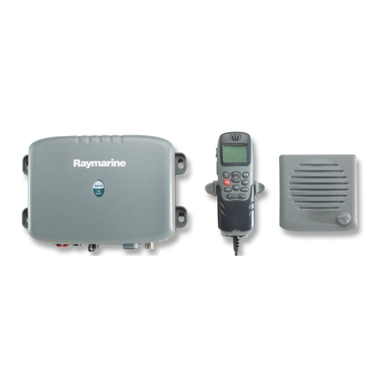
Raymarine RAY 240 Manual
Vhf radio
Hide thumbs
Also See for RAY 240:
- User manual (80 pages) ,
- Installation manual (2 pages) ,
- User manual (72 pages)

Related Manuals for Raymarine RAY 240


Summary of Contents for Raymarine RAY 240
- Page 1 Raymarine Limited RAY 240 VHF Radio Technical Description FCC ID PJ5RAY240 IC: 4069B-RAY240 Raymarine Limited. Registered in England. Company no. 1177969 Registered Office: Anchorage Park, Portsmouth P03 5TD...
-
Page 2: Table Of Contents
RF PCB Circuit Description ................11 RAY 240 Handset Block Diagram ................14 RAY 240 Handset Circuit Description ................ 15 RAY 240 Active Speaker Block Diagram ..............18 RAY 240 Active Speaker Circuit Description............. 19 Page 2 Raymarine Limited. Registered in England. Company no. 1177969... -
Page 3: Ray 240 System Interconnection Diagram
Ray240 VHF Radio System Interconnection Diagram VHF Antenna Transceiver (5552-001) Power Connector Seatalk Connector Antenna Connector Handset 1 Connector Handset 2 Connector Telephone Line 8 way Female SO-239 UHF Female 8 way Female 8 way Female Connector Handset 2 (5552-003) Speaker 2 (5552-005) PL-239 UHF... -
Page 4: Ray 240 Transceiver Unit Interconnection Diagram
Board to Board Connector, 12-way Telephone Line Connector Signal Name Type +12V no connection Signal Name Type no connection no connection connector connector Telephone Board designation designation assy no. TBD RING no connection HOOK no connection MUTE no connection AUDIO TO TEL AUDIO FROM TEL Power Connector 8 way Female... -
Page 5: Processor And Interconnect Pcbs Block Diagram
Seatalk Connector Power Connector Seatalk Connector Power Connector BDM Connector RAY240 Hardware Block Diagram +5VD +12V Power Connector +5V Regulators +5VA Protection Processor Board & Interconnect Board & Filtering can_b_5v Voltage Seatalk 2 Monitor can_b_0v Power Supply NMEA0183 Seatalk Seatalk NMEA0183 Seatalk 2 radio_power_on_off... -
Page 6: Processor And Interconnect Pcbs Circuit Description
RAY 240 Processor and Interconnect PCBs Circuit Description Introduction The processor board is the central control unit of the Ray240 VHF system. It controls the system in response to commands received from the handsets and, conversely, reports the system status to the handsets for display. - Page 7 FSK signal is determined by very accurately controlling the rate at which the digital inputs to the FSK modulator are switched. Page 7 Raymarine Limited. Registered in England. Company no. 1177969 Registered Office: Anchorage Park, Portsmouth P03 5TD...
- Page 8 The second of the microcontroller’s UARTs is used for serial communications with external systems, such as GPS. The UART can be connected either to a Seatalk interface (Raymarine’s proprietary single wire half-duplex communications interface) or to an NMEA0183 transmitter and receiver.
- Page 9 A spare discrete nominally called “mute” • An I2C serial communications interface, used for controlling a DTMF generator on the telephone interface board Page 9 Raymarine Limited. Registered in England. Company no. 1177969 Registered Office: Anchorage Park, Portsmouth P03 5TD...
-
Page 10: Rf Pcb Block Diagram
20.945 MHz 139.625 MHz CH70 Receiver 16.445 MHz Filter Filter Noise Tuning Tuning 16.9 MHz FM Detector Analogue signal from Digital signal Processor board Page 10 Raymarine Limited. Registered in England. Company no. 1177969 Registered Office: Anchorage Park, Portsmouth P03 5TD... -
Page 11: Rf Pcb Circuit Description
12.5 kHz steps. When the radio is transmitting, the VCO operates between 155.000 MHz and 165.000 MHz, and when the radio is in receive mode, operates between 133.600 MHz and 141.875 Page 11 Raymarine Limited. Registered in England. Company no. 1177969 Registered Office: Anchorage Park, Portsmouth P03 5TD... - Page 12 The filters for the CH70 receiver are tuned using the method mentioned above, however these voltages remain at a fixed level. The processor PCB also generates these voltages. Page 12 Raymarine Limited. Registered in England. Company no. 1177969 Registered Office: Anchorage Park, Portsmouth P03 5TD...
- Page 13 This device has an output pin whose voltage is relative to how noise the received signal is. This voltage is used by the processor PCB to determine whether the squelch should be opened or closed. Page 13 Raymarine Limited. Registered in England. Company no. 1177969 Registered Office: Anchorage Park, Portsmouth P03 5TD...
-
Page 14: Ray 240 Handset Block Diagram
M I C R O C O N TR O LLE R M SP430F1 35 KEY PAD PU SH - TO - TALK BAC KLI G H TI N G D I STR ESS Page 14 Raymarine Limited. Registered in England. Company no. 1177969 Registered Office: Anchorage Park, Portsmouth P03 5TD... -
Page 15: Ray 240 Handset Circuit Description
The key matrix can thus be driven to allow only one key to be active at any time and will not ‘lockout’ the distress key or PTT key if any other key on the keypad is pressed. Page 15 Raymarine Limited. Registered in England. Company no. 1177969 Registered Office: Anchorage Park, Portsmouth P03 5TD... - Page 16 The interface that the system uses to communicate to the main processor is based on the Seatalk interface that is widely used in Raymarine equipment. The hardware configuration has been based very closely on that used on many other Raymarine equipment, with some slight resistor changes to ensure correct operability with a 3.3V processor supply.
- Page 17 The PTT switch is monitored by the processor and is therefore ignored if pressed whilst initial setup is undergone. After initialization has completed, the PTT switch position is echoed onto the PTT line by TR10, operated by the micro-controller. Page 17 Raymarine Limited. Registered in England. Company no. 1177969 Registered Office: Anchorage Park, Portsmouth P03 5TD...
-
Page 18: Ray 240 Active Speaker Block Diagram
ALAR M O V ER R I D E AU D I O I N M O D E SPEAKER VO LU M E 6W AM PLI FI ER Page 18 Raymarine Limited. Registered in England. Company no. 1177969 Registered Office: Anchorage Park, Portsmouth P03 5TD... -
Page 19: Ray 240 Active Speaker Circuit Description
DC level of the input and output pins remain on half the supply voltage. The device is in mute mode when the mode pin is at a voltage greater than 3V and less than (VCC 1 .5 V). Page 19 Raymarine Limited. Registered in England. Company no. 1177969 Registered Office: Anchorage Park, Portsmouth P03 5TD... - Page 20 Alarm mode is activated in the RAY240 main processor box by pulling the signal line high t0 12V. When the signal exceeds approximately 6V, the alarm mode in the amplifier is entered. Page 20 Raymarine Limited. Registered in England. Company no. 1177969 Registered Office: Anchorage Park, Portsmouth P03 5TD...