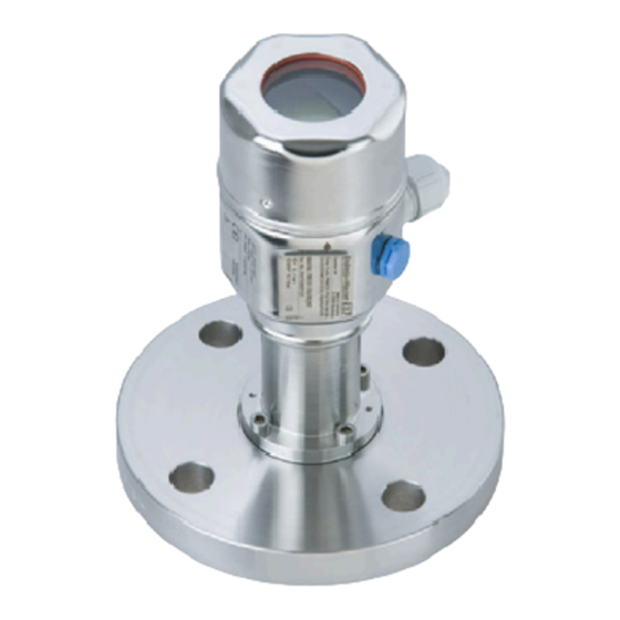
Endress+Hauser Cerabar M PMP55 Operating Instructions Manual
Process pressure measurement io-link pressure transmitter
Hide thumbs
Also See for Cerabar M PMP55:
- Operating instructions manual (134 pages) ,
- Technical information (134 pages) ,
- Owner's manual (120 pages)
Table of Contents
Advertisement
Quick Links
KA01522P/00/EN/02.22-00
71581314
2022-07-27
Products
Brief Operating Instructions
Cerabar M PMC51, PMP51,
PMP55
Process pressure measurement
IO-Link
Pressure transmitter
These Brief Operating Instructions are not a substitute for the
Operating Instructions pertaining to the device.
Detailed information about the device can be found in the
Operating Instructions and the additional documentation.
Available for all device versions via
• Internet:
www.endress.com/deviceviewer
• Smartphone/tablet: Endress+Hauser Operations app
Solutions
Services
Advertisement
Table of Contents

Related Manuals for Endress+Hauser Cerabar M PMP55


Summary of Contents for Endress+Hauser Cerabar M PMP55
- Page 1 These Brief Operating Instructions are not a substitute for the Operating Instructions pertaining to the device. Detailed information about the device can be found in the Operating Instructions and the additional documentation. Available for all device versions via • Internet: www.endress.com/deviceviewer • Smartphone/tablet: Endress+Hauser Operations app...
-
Page 2: Associated Documentation
Associated documentation Order code: XXXXX-XXXXXX Ser. no.: XXXXXXXXXXXX Ext. ord. cd.: XXX.XXXX.XX Serial number www.endress.com/deviceviewer Endress+Hauser Operations App A0023555 About this document Document function The Brief Operating Instructions contain all the essential information from incoming acceptance to initial commissioning. Endress+Hauser... -
Page 3: Symbols Used
2.2.3 Tool symbols Symbol Meaning Allen key A0011221 Open-ended wrench A0011222 2.2.4 Symbols for certain types of information Symbol Meaning Permitted Procedures, processes or actions that are permitted. Forbidden Procedures, processes or actions that are forbidden. Endress+Hauser... -
Page 4: Registered Trademarks
• GORE-TEX® trademark of W.L. Gore & Associates, Inc., USA Basic safety instructions Requirements for personnel Personnel must meet the following requirements for their tasks: ‣ Trained, qualified specialists must have a relevant qualification for this specific function and task Endress+Hauser... -
Page 5: Designated Use
The manufacturer is not liable for damage caused by improper or non-designated use. Verification for borderline cases: ‣ For special fluids and fluids for cleaning, Endress+Hauser is glad to provide assistance in verifying the corrosion resistance of fluid-wetted materials, but does not accept any warranty or liability. -
Page 6: Product Safety
• Do the data on the nameplate correspond to the order specifications and the delivery note? • Is the documentation available? • If required (see nameplate): Are the safety instructions (XA) present? If one of these conditions is not fulfilled, please contact your Endress+Hauser sales office. Storage and transport 4.2.1 Storage conditions Use original packaging. -
Page 7: Installation
The integrity of the thread must be checked regularly. Also, the thread may need to be re- tightened with the maximum tightening torque of 7 Nm (5.16 lbf ft). Teflon tape is recommended for sealing the ½" NPT thread. Endress+Hauser... - Page 8 The orientation depends on the measuring application. • Do not clean or touch the membrane with hard or pointed objects. • The device must be installed as follows in order to comply with the cleanability requirements of the ASME-BPE (Part SD Cleanability): Endress+Hauser...
- Page 9 • at a point in the tank which could be affected by pressure pulses from the agitator • The calibration and functional test can be carried out more easily if you mount the device downstream of a shutoff device. Endress+Hauser...
- Page 10 Not in the vicinity of heating or cooling lines ‣ Insulate if the ambient temperature is below or above the reference temperature ‣ Mount with a bending radius ≥ 100 mm (3.94 in)! ‣ Do not use the capillaries as a carrying aid for the diaphragm seals! Endress+Hauser...
-
Page 11: Electrical Connection
Check that the supply voltage corresponds to the supply voltage indicated on the nameplate. Switch off the supply voltage before connecting the device. Connect the device in accordance with the following diagram. Switch on the supply voltage. IO-Link L– A0045628 Supply voltage + 4-20 mA Supply voltage - C/Q (IO-Link communication) Endress+Hauser... -
Page 12: Connecting The Measuring Unit
(20 to 12 AWG) Cable specification 6.4.1 IO-Link Endress+Hauser recommends using twisted, four-core cable. Load for current output In order to guarantee sufficient terminal voltage, a maximum load resistance R (including line resistance) must not be exceeded depending on the supply voltage U of the supply unit. -
Page 13: Operation Methods
See Operating Instructions. Operation Operation methods 7.1.1 Operation without an operating menu Operation methods Explanation Graphic Description Local operation without The device is operated using the → 15 device display operating keys on the electronic insert. Display Zero Span A0045577 Endress+Hauser... - Page 14 It also provides the option of configuring the measuring device while in operation. Characteristics of the IO-Link interface: • IO-Link specification: Version 1.1 • IO-Link Smart Sensor Profile 2nd Edition • Speed: COM2; 38.4 kBaud • Minimum cycle time: 10 ms • Process data width: 14 Byte Endress+Hauser...
- Page 15 The operating keys are located in the measuring device on the electronic insert. IO-Link Display Zero Span A0045576 Operating keys for lower range value (zero) and upper range value (span) Green LED to indicate successful operation Slot for optional local display Slot for M12 plug Endress+Hauser...
- Page 16 90 mm (3.54 in) long cable. The display of the device can be turned in 90° stages (see figure steps 4 to 6). Depending on the installation position of the device, this makes it easy to operate the device and read the measured values. Endress+Hauser...
- Page 17 • Three keys for operation • Simple and complete menu guidance as parameters are split into several levels and groups • Each parameter is given a 3-digit parameter code for easy navigation • Comprehensive diagnostic functions (fault and warning message etc.) Endress+Hauser...
- Page 18 The device is in the Service mode (e.g. during a simulation). A0013959 Error message "Maintenance required" Maintenance is required. The measured value is still valid. A0013957 Error message "Failure detected" An operating error has occurred. The measured value is no longer valid. A0013956 Endress+Hauser...
- Page 19 ("Deutsch" is the language selected). English • Use to exit the edit mode for the parameter. 7.4.3 Operating example: User-definable parameters Example: setting the "Set URV (014)" parameter from 100 mbar (1.5 psi) to 50 mbar (0.75 psi). Endress+Hauser...
- Page 20 Use the key to accept the applied pressure for pos. zero adjustment. The device been accepted! confirms the adjustment and goes back to the "Pos. zero adjust" parameter. 4 Cancel Use to exit the edit mode for the parameter. Confirm Endress+Hauser...
-
Page 21: System Integration
• The device is configured for the "Pressure" measuring mode as standard. You can change the measuring mode via the "Measuring mode" parameter → 24. • The pressure applied must be within the nominal pressure limits of the measuring cell. See information on the nameplate. Endress+Hauser... - Page 22 Press the Span key for at least 3 s. LED on the electronic insert is lit briefly. The applied pressure for the upper range value has been accepted. Endress+Hauser...
- Page 23 Press the Zero key for at least 3 s. LED on the electronic insert is lit briefly. The applied pressure was saved as the lower pressure value ("Empty pressure") and assigned to the lower level value ("Empty calibration"). Endress+Hauser...
-
Page 24: Commissioning With An Operating Menu
Select the menu language for the local display. Selection • English • Another language (as selected when ordering the device) • A third language where applicable (language of the place of manufacture) Factory setting English Measuring mode (005) Write permission Operator/Maintenance/Expert Endress+Hauser... - Page 25 • inH2O, ftH2O • Pa, kPa, MPa • psi • mmHg, inHg • kgf/cm Factory setting mbar or bar depending on the nominal measuring range of the measuring cell, or as per order specifications. 9.2.2 Pos. zero adjust Corrected press. (172) Endress+Hauser...
- Page 26 Selection • Confirm • Cancel Factory setting Cancel Pos. zero adjust (007) (gauge pressure measuring cells) Write permission Operator/Maintenance/Expert Description Pos. zero adjustment – the pressure difference between zero (set point) and the measured pressure need not be known. Endress+Hauser...
-
Page 27: Configuring Pressure Measurement
Due to the orientation of the device, there may be pressure shifts in the measured value, i.e. the measured value is not zero in an unpressurized state. For information on how to perform position adjustment, see → 25. Endress+Hauser... - Page 28 Enter the value for the "Set URV" parameter (here 300 mbar (4.5 psi)) and confirm. This pressure value is assigned to the upper current value (20 mA). Result: The measuring range is configured for 0 to +300 mbar (0 to 4.5 psi). Endress+Hauser...
- Page 29 The pressure for the upper range value (20 mA value) is present at the device, here 300 mbar (4.5 psi) for example. Select the "Get URV" parameter. Menu path: Setup → Extended setup → Current output → Get URV Endress+Hauser...
- Page 30 Description Confirm the value present at the device by selecting "Confirm". The pressure value present is assigned to the upper current value (20 mA). Result: The measuring range is configured for 0 to +300 mbar (0 to 4.5 psi). Endress+Hauser...
- Page 32 *71581314* 71581314 www.addresses.endress.com...