Endress+Hauser Cerabar M PMC51 Operating Instructions Manual
Process pressure measurement
Hide thumbs
Also See for Cerabar M PMC51:
- Technical information (134 pages) ,
- Operating instructions manual (134 pages) ,
- Brief operating instructions (32 pages)
Table of Contents
Advertisement
Quick Links
KA01031P/00/EN/05.16
71316885
Products
Brief Operating Instructions
Cerabar M
PMC51, PMP51, PMP55
Process pressure measurement
These Instructions are Brief Operating Instructions; they are not
a substitute for the Operating Instructions pertaining to the
device.
Detailed information about the device can be found in the Ope-
rating Instructions and the other documentation:
Available for all device versions via:
– Internet:
www.endress.com/deviceviewer
– Smart phone/tablet: Endress+Hauser Operations App
Solutions
Services
Advertisement
Table of Contents

Related Manuals for Endress+Hauser Cerabar M PMC51


Summary of Contents for Endress+Hauser Cerabar M PMC51
- Page 1 Operating Instructions pertaining to the device. Detailed information about the device can be found in the Ope- rating Instructions and the other documentation: Available for all device versions via: – Internet: www.endress.com/deviceviewer – Smart phone/tablet: Endress+Hauser Operations App...
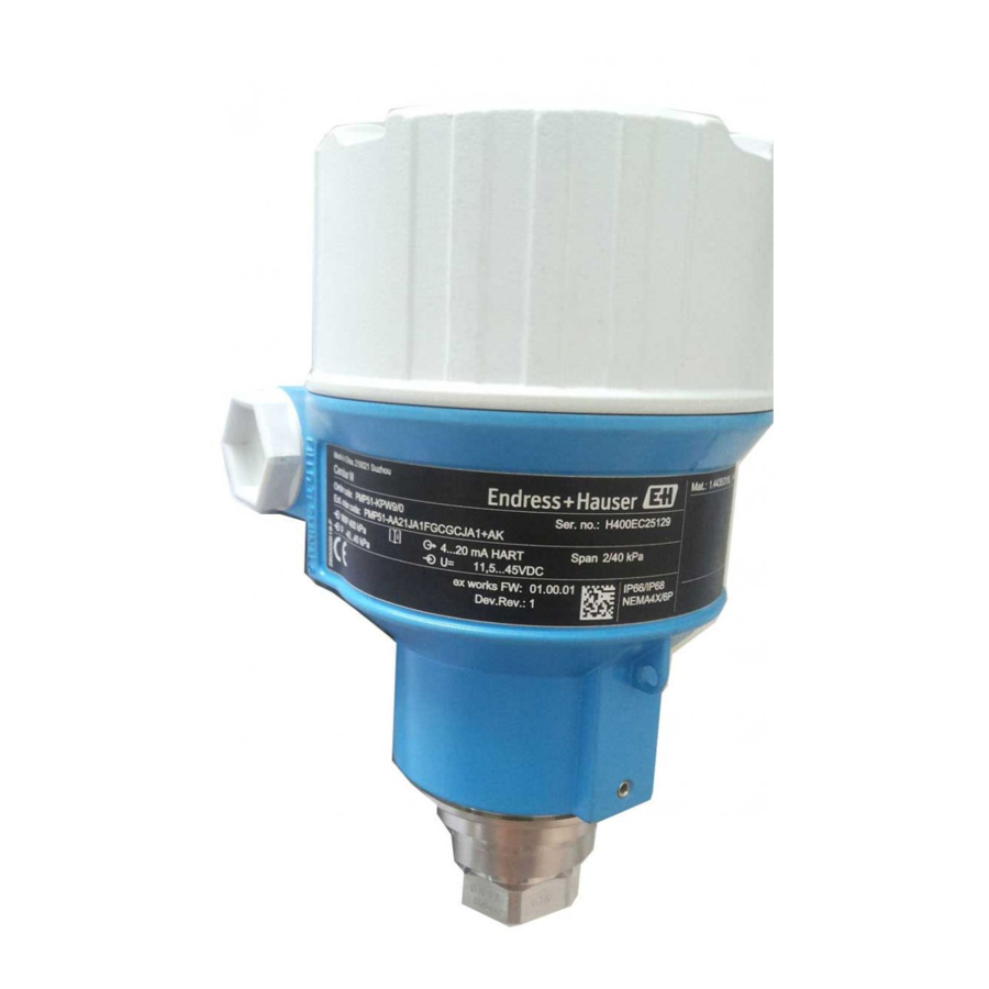
- Page 2 Cerabar M PROFIBUS PA Order code: XXXXX-XXXXXX Ser. no.: XXXXXXXXXXXX Ext. ord. cd.: XXX.XXXX.XX Serial number www.endress.com/deviceviewer Endress+Hauser Operations App A0023555 Endress+Hauser...
-
Page 3: Table Of Contents
8.6 Pressure measurement ................47 Endress+Hauser... -
Page 4: Document Information
A connection that has to be connected ground prior to establishing any other to the plant grounding system: This may connections. be a potential equalization line or a star grounding system depending on national or company codes of practice. Endress+Hauser... - Page 5 Reference to page A0015484 Reference to graphic A0015487 1. 2. , ... Series of steps Result of a sequence of actions A0018343 Visual inspection A0015502 Indicates how to navigate to the parameter using the display and operating module A0015502 Endress+Hauser...
- Page 6 Registered label of E.I. Du Pont de Nemours & Co., Wilmington, USA ® TRI-CLAMP Registered label of Ladish & Co., Inc., Kenosha, USA ® PROFIBUS PA Trademark of the PROFIBUS User Organization, Karlsruhe, Germany ® GORE-TEX Registered label of W.L. Gore & Associates, Inc., USA Endress+Hauser...
-
Page 7: Basic Safety Instructions
The manufacturer is not liable for damage caused by improper or non-designated use. Verification for borderline cases: For special fluids and fluids for cleaning, Endress+Hauser is glad to provide assistance in verifying the corrosion resistance of fluid-wetted materials, but does not accept any warranty or liability. -
Page 8: Hazardous Area
Conversions to the device Unauthorized modifications to the device are not permitted and can lead to unforeseeable dangers: ‣ If, despite this, modifications are required, consult with Endress+Hauser. Repair To ensure continued operational safety and reliability, ‣ Carry out repairs on the device only if they are expressly permitted. -
Page 9: Scope Of Delivery
The devices comply with the applicable standards and regulations as listed in the EC Declaration of Conformity and thus comply with the statutory requirements of the EC Directives. Endress+Hauser confirms the conformity of the device by affixing to it the CE mark. -
Page 10: Installation Conditions
‣ The integrity of the thread must be checked regularly and the thread may need to be re-tightened with the maximum tightening torque of 7 Nm (5.16 lbf ft). Teflon tape is recommended for sealing the ½" NPT thread. Endress+Hauser... -
Page 11: Installing
• For PMP55, please refer to Section 4.5.2 "Installation instructions for devices with diaphragm seals – PMP55", ä 12. • Endress+Hauser offers a mounting bracket for installing on pipes or walls. ä 14, Section 4.5.5 "Wall and pipe mounting (optional)". - Page 12 • Cerabar M devices with diaphragm seals are screwed in, flanged or clamped, depending on the type of diaphragm seal. • Please note that the hydrostatic pressure of the liquid columns in the capillaries can cause zero point shift. The zero point shift can be corrected. Endress+Hauser...
- Page 13 4.5.3 Seal for flange mounting NOTICE Corrupted measurement results. The seal is not allowed to press against the process isolating diaphragm as this could affect the measurement result. ‣ Ensure that the seal is not touching the process isolating diaphragm. Endress+Hauser...
- Page 14 Installation Cerabar M PROFIBUS PA A0017743 Fig. 1: Process isolating diaphragm Seal 4.5.4 Thermal insulation – PMP55 See operating instructions. 4.5.5 Wall and pipe mounting (optional) See operating instructions. Endress+Hauser...
- Page 15 Mount the housing on a wall or pipe using the mounting bracket (item 7). When mounting on a pipe, tighten the nuts on the bracket uniformly with a torque of at least 5 Nm (3.69 lbs ft). Mount the cable with a bending radius (r) 120 mm (4.72 in). Endress+Hauser...
-
Page 16: Mounting Of The Profile Seal For Universal Process Mounting Adapter
4.7.1 Closing the cover on the stainless steel housing A0028497 Fig. 3: Closing the cover Endress+Hauser... -
Page 17: Post-Installation Check
1. Check that the supply voltage corresponds to the supply voltage indicated on the nameplate. 2. Switch off the supply voltage before connecting the device. 3. Remove housing cover. 4. Guide the cable through the gland. Preferably use a twisted, shielded two-wire cable. Endress+Hauser... - Page 18 5. Connect the device in accordance with the following diagram. 6. Screw down the housing cover. 7. Switch on the supply voltage. A0029967 PROFIBUS PA electrical connection External ground terminal Grounding terminal Supply voltage: 9 to 32 VDC (Segment coupler) Terminals for supply voltage and signal Endress+Hauser...
-
Page 19: Connecting The Measuring Unit
11 mA ±1 mA, switch-on current corresponds to IEC 61158-2, Clause 21. 5.2.3 Terminals • Supply voltage and internal ground terminal: 0.5 to 2.5 mm (20 to 14 AWG) • External ground terminal: 0.5 to 4 mm (20 to 12 AWG) Endress+Hauser... -
Page 20: Potential Equalization
• Are all screws firmly tightened? • Are the housing covers screwed down tight? As soon as voltage is applied to the device, the green LED on the electronic insert lights up briefly or the connected onsite display lights up. Endress+Hauser... -
Page 21: Operation
Graphic illustration Description ä 27 Local operation The device is operated using with device display the operating keys on the device display. – ä 31 Remote operation via The device is operated using FieldCare the FieldCare operating tool. Endress+Hauser... -
Page 22: Operation Without An Operating Menu
ä 32 Remote operation via The device is operated using the PDM tool. Operation without an operating menu 6.2.1 Position of operating elements The operating key and DIP switches are located on the electronic insert in the device. Endress+Hauser... - Page 23 Damping is switched off. Damping is switched on. The output signal follows measured value The output signal follows measured value changes with the delay time . changes without any delay. Endress+Hauser...
- Page 24 If the LED on the electronic insert lights up briefly, the pressure applied has been accepted for position adjustment. If the LED does not light up, the pressure applied was not accepted. Observe the input limits. For error messages, see operating instructions. Endress+Hauser...
-
Page 25: Operation With An Operating Menu
6.3.2 Structure of the operating menu User role Submenu Meaning/use Operator Language Only consists of the "Language" parameter (000) where the operating language for the device is specified. The language can always be changed even if the device is locked. Endress+Hauser... - Page 26 Contains all the parameters for configuring the functions that go beyond the actual measurement (e.g. totalizer). • Diagnosis Contains all the parameters that are needed to detect and analyze operating errors. For an overview of the entire operating menu: see operating instructions. Endress+Hauser...
- Page 27 The display of the device can be turned in 90° stages (see figure steps 4 to 6). Depending on the orientation of the device, this makes it easy to operate the device and read the measured values. A0028500 Functions: • 8-digit measured value display including sign and decimal point. Endress+Hauser...
- Page 28 The following table illustrates the symbols that can appear on the onsite display. Four symbols can occur at one time. Symbol Meaning Lock symbol The operation of the device is locked. To unlock the device, ä 31, Locking/unlocking operation. Communication symbol Data transfer via communication Endress+Hauser...
- Page 29 – You are in a menu at a selection level. Each time you press the keys simultaneously, you go up a level in the menu. Operating example: Parameters with a picklist Example: selecting "Deutsch" as the language of the menu. Endress+Hauser...
- Page 30 5 0 0 0 0 0 mbar Switch to the "" symbol with the key. Use to save the new value and exit the editing mode. 5 0 0 0 0 mbar See next graphic. Endress+Hauser...
- Page 31 The device confirms the adjustment and goes back to the "Pos. zero adjust" parameter. Abort Exit the edit mode for the parameter with . Confirm 6.3.4 Operation via FieldCare See operating instructions. 6.3.5 Locking/unlocking operation See operating instructions. 6.3.6 Resetting to factory settings (reset) See operating instructions. Endress+Hauser...
-
Page 32: Profibus Pa Communication Protocol
Hardware addressing A hardware address is set as follows: Set the DIP switch 8 (SW/HW) to "Off". Set the address with DIP switches 1 to 7. The change of address takes effect after 10 seconds. The device is restarted. Endress+Hauser... -
Page 33: Commissioning Without An Operating Menu
(depending on the setting in the "Alarm behavior" (050) parameter): "S140 Working range P" or "F140 Working range P" "S841 Sensor range" or "F841 Sensor range" Endress+Hauser... -
Page 34: Function Check
Does the LED on the electronic insert light up briefly? Applied pressure for position adjustment has been Applied pressure for position adjustment has not been accepted. accepted. Observe the input limits. Observe warning on commissioning ( ä 33) Endress+Hauser... -
Page 35: Commissioning With An Operating Menu (Onsite Display/Fieldcare)
Commissioning comprises the following steps: Function check ä 35 Selecting the language, measuring mode and pressure unit ä 35 Position adjustment ä 37 Configuring measurement: – Pressure measurement ä 47 ff – Level measurement ä 37 ff Endress+Hauser... - Page 36 Setup Press. eng. unit (125) • mbar, bar • mmH2O, mH2O, • inH2O, ftH2O • Pa, kPa, MPa • psi • mmHg, inHg • kgf/cm Factory setting: mbar or bar depending on the sensor nominal measuring range, or as per order specifications Endress+Hauser...
-
Page 37: Position Zero Adjustment
You have a choice of two methods for calculating the level: "In pressure" and "In height". The table in the "Overview of level measurement" section that follows provides you with an overview of these two measuring tasks. Endress+Hauser... - Page 38 Select the "Level" measuring mode via the "Measuring mode (005)" parameter. Menu path: Setup Measuring mode (005) Select a pressure unit via the "Press. eng. unit (125)" parameter, here "mbar" for example. Menu path: Setup Press. eng. unit (125) Endress+Hauser...
- Page 39 See Table, Step 7. process medium in the "Process density (035)" See Table, Step 8. parameter. Menu path: Setup Extended setup Level Process density (035). Result: The measuring range is set for 0 to 3 m (9.8 ft). Endress+Hauser...
- Page 40 Menu path: Setup Extended Setup Level Level selection (024) Select a volume unit via the "Unit before lin (025)" parameter, here "l" (liter) for example. Menu path: Setup Extended Setup Level Unit before lin (025) Endress+Hauser...
- Page 41 See Table, Step 7. See Table, Step 8. See Table, Step 9. See Table, Step 10. The measured variables %, level, volume and mass are available for this level mode. See operating instructions "Unit before lin (025)". Endress+Hauser...
- Page 42 Fig. 11: Calibration with reference pressure – parameter, here "l" (liter) for example. wet calibration Menu path: Setup Extended Setup Level See Table, Step 8. Unit before lin (025) See Table, Step 9. See Table, Step 9. Endress+Hauser...
- Page 43 Menu path: Setup Extended Setup Level Process density (035) Result: The measuring range is set for 0 to 1000 l (264 gal). The measured variables %, level, volume and mass are available for this level mode operating instructions "Unit before lin (025)". Endress+Hauser...
- Page 44 Fig. 13: Calibration without reference pressure – (026)" parameter, here "m" for example. dry calibration Menu path: Setup Extended Setup Level Height unit (026) See Table, Step 7. See Table, Step 8 and 10. See Table, Step 9 and 11. Endress+Hauser...
- Page 45 Process density (035). See Table, Step 11. Result: The measuring range is set for 0 to 1000 l (264 gal). The measured variables %, level, volume and mass are available for this level mode operating instructions "Unit before lin (025)". Endress+Hauser...
-
Page 46: Linearization
Full pressure (032) see operating instructions Full height (033) see operating instructions Density unit (127) see operating instructions Adjust density (034) see operating instructions Process density (035) see operating instructions Level before lin. (019) see operating instructions Linearization See operating instructions. Endress+Hauser... -
Page 47: Pressure Measurement
Menu path: Setup Press. eng. unit (125) Where necessary scale the "Output value (Out Value)" of the Analog Input Block, see operating instructions, parameter descriptions for "Proc value scale" and "Output scale". Result: The measuring range is configured for 0 to +300 mbar (4.35 psi). Endress+Hauser... - Page 48 71316885 www.addresses.endress.com...