
Related Manuals for Graco Dispensit 710


Summary of Contents for Graco Dispensit 710
- Page 1 sales@artisantg.com artisantg.com (217) 352-9330 | Visit our website - Click HERE...
- Page 2 Instructions Dispensit 710 332094C Depending on valve configuration, this valve can be used to dispense the following: Acrylics, Conformal Coatings, Epoxies, Lubricants, RTV Silicones, Silicone Oils, Solder Flux, Solder Mask, UV Curables Dispense Valve 100psi (0.69 MPa, 6.9 bar) Maximum Air Working Pres- sure 1200psi (82.7 bar) Maximum Material Inlet Pressure...
-
Page 3: Table Of Contents
Graco Standard Warranty ....22 Graco Information ......22... -
Page 4: Warnings
Warnings Warnings The following warnings are for the setup, use, grounding, maintenance, and repair of this equipment. The exclama- tion point symbol alerts you to a general warning and the hazard symbols refer to procedure-specific risks. When these symbols appear in the body of this manual or on warning labels, refer back to these Warnings. Product-specific hazard symbols and warnings not covered in this section may appear throughout the body of this manual where applicable. - Page 5 Warnings WARNING PERSONAL PROTECTIVE EQUIPMENT Wear appropriate protective equipment when in the work area to help prevent serious injury, including eye injury, hearing loss, inhalation of toxic fumes, and burns. Protective equipment includes but is not limited to: • Protective eyewear, and hearing protection. •...
-
Page 6: General Information
General Information General Information General Accessories Graco offers a full line of standard and custom accesso- The Model 710 Dispense Valve is an On/Off valve ries for your dispensing needs including: designed for a continuous flow of viscous material through a dispense needle in automatic, semi-automatic •... -
Page 7: Setup
Setup Setup NOTE: See Typical Installation diagram. 3. Connect each 1/4 in. outside diameter supplied air line to the corresponding control solenoid. See Typ- 1. Perform Setup procedure for feed system ical Feed System Components starting on page 7. components. See feed system manual(s). 4. - Page 8 Setup Typical Feed System Components 5 Gallon Pail Cover 5 Gallon Pail Cover with Diaphragm with Diaphragm Pump Pump and Agitator 20 oz Cartridge Feed with Mounting Post 1 Gallon Ram and Pump WARNING DO NOT SERVICE WITHOUT REMOVING AIR PRESSURE AND WEARING SAFETY GLASSES.
- Page 9 Setup Typical Feed System Components (continued) 5 Gallon Tank with Diaphragm Pump and Stand 5 Gallon Tank with 5:1 Pump and Stand 10 Gallon Tank with Diaphragm Pump, Agitator, 10 Gallon Tank with 5:1 Pump, Agitator, Vacuum, Vacuum, and Stand and Stand 332094C...
-
Page 10: Description Of Operation
Description of Operation Description of Operation 1. The normal “ready” state of the system is as follows: 3. Material flows through the Valve Body (5) and out • The material supply line is filled with dispens- through the Needle Block (23). Volume can be var- able material. -
Page 11: Setup Procedure
Description of Operation Setup Procedure Mounting Dispense Valve Mounting holes are drilled through the valve body. The valve may be tilted to a maximum of 60 degrees from the vertical depending on the appli- cation. Air Controller Operation of the Model 710 Dispense Valve requires a controller that can provide the following: •... -
Page 12: Operating Procedures
Operating Procedures Operating Procedures If there are any problems in getting started, refer to NOTE: The material pressure will vary depending on the the Troubleshooting section on page 16. application. Dry System Checkout This is an initial checkout to determine if the setup has •... -
Page 13: Operation Adjustments
Operating Procedures Operation Adjustments Air Supply Adjustment The air pressure to the controller and material supply regulator is typically 70 psi (4.8 bar). Do not exceed 100 psi (6.9 bar) pressure to the dispense valve. However, the material supply pressure must be adjusted accord- ing to the type of material being dispensed. -
Page 14: Periodic Maintenance
Periodic Maintenance Periodic Maintenance Note that the Gaskets (24) rarely require replacement and are not provided in the seal kit. Retain them for reuse after cleaning. Replacements are available from the factory or your Dispensit dealer. Pressure Relief Procedure 1. Turn off the air supply and remove the Connectors (28) from the controller. -
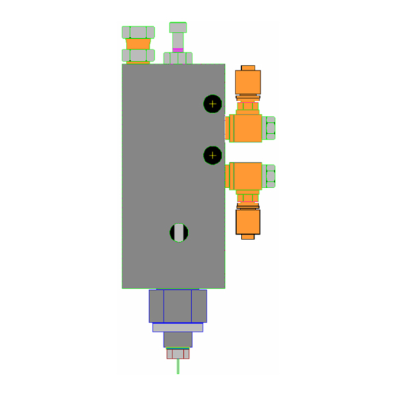
Page 15: Model 710 General Illustration
Periodic Maintenance Model 710 General Illustration NEEDLE SEAT ADAPTER U-CUP SEAL VALVE SLEEVE RETAINING PLUG PISTON ASSEMBLY O-RING VALVE BODY O-RING O-RING HEX NUT, #10-32 POSIPAK SEAL ADJUSTMENT SCRW, #10-32 x 1-1/2 SPACER FITTING RETAINING TUBE NEEDLE BLOCK U-CUP SEAL GASKET WASHER ELBOW... -
Page 16: Assembly
Periodic Maintenance Assembly 12. Carefully install the Needle Block (23) through the Gasket (24) and into the Needle Seat (1). Refer to the illustration on page 14 and the drawings at 13. Position the O-ring (18) on the Needle Seat (1) and the back of this manual for your exact model. -
Page 17: Troubleshooting
Troubleshooting Troubleshooting Material Continues to Flow After If operating difficulties are encountered, review the symptoms below. With each problem there are one or Shut Off more possible causes that should be investigated to resolve the situation. This can be due to material preventing the piston from seating properly into the needle seat or to a worn piston Nothing Happens and/or needle seat. -
Page 18: Parts
Parts Parts 710 Valve 332094C... - Page 19 Parts 710 Valve Components Part Description 61/2904-GN/11 TUBE 61/2904-YL/11 TUBE 94/0170/99 FITITNG, CONN 94/0740-A/99 FITTING, ELBOW, SWVL 94/0740-B/99 CONNECTOR 95/0503/00 O-RING, VIT 95/0515/00 O-RING, VIT 95/0600/01 SEAL, U-CUP 95/0883/11 SEAL, POSPK 95/0905/00 O-RING, VIT A9000005 SLEEVE, 710 A9000006 CAP, 710, END CAP A9000007 SPACER, 710, SPACER NOTES A9000011...
-
Page 20: Model 710 Recommended Spare Parts
Model 710 Recommended Spare Parts Model 710 Recommended Spare Parts NOTE: These parts are routine supply items or wear parts not covered by warranty for normal wear. Quantity Description Part Number SEAL KIT,710 see assembly drawing for part number PISTON see assembly drawing for part number NEEDLE SEAT see assembly drawing for part number... -
Page 21: General Guidelines For O-Rings And U-Cup Seals
General Guidelines for O-Rings and U-Cup Seals U-Cup Seal Guidelines Sizes and materials of construction for O-rings and U-cup seals are selected by Graco Inc. based on com- patibility with the chemicals to which they will be • Always replace a U-cup seal with the identical one exposed. -
Page 22: Technical Data
Wetted Parts........Metering Valve: 303/304, 404, fluoroelastomer, EPDM Graco-supplied Feed System Hoses and Fittings: Mild... -
Page 23: Graco Standard Warranty
With the exception of any special, extended, or limited warranty published by Graco, Graco will, for a period of twelve months from the date of sale, repair or replace any part of the equipment determined by Graco to be defective.