Table of Contents
Advertisement
Quick Links
Instructions
Dispensit
Usage Statement – Depending on valve configuration this valve can be used to dispense the following:
Acrylics • Conformal Coatings • Epoxies • Lubricants • RTV Silicones • Silicone Oils • Solder Flux • Solder Mask • UV Curables
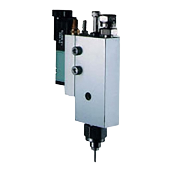
Dispense Valve
100psi (0.69 MPa, 6.9 bar) Maximum Working Pressure
Important Safety Instructions
Read all warnings and instructions in this manual.
Save these instructions.
See Page 3 for model information, including maximum
working pressure and approvals.
- 710
332094B
EN
Advertisement
Table of Contents

Related Manuals for Graco Dispensit-710


Summary of Contents for Graco Dispensit-710
- Page 1 Instructions 332094B Dispensit - 710 Usage Statement – Depending on valve configuration this valve can be used to dispense the following: Acrylics • Conformal Coatings • Epoxies • Lubricants • RTV Silicones • Silicone Oils • Solder Flux • Solder Mask • UV Curables Dispense Valve 100psi (0.69 MPa, 6.9 bar) Maximum Working Pressure Important Safety Instructions...
-
Page 2: Table Of Contents
® DISPENSIT MODEL 710 DISPENSE VALVE OPERATING & MAINTENANCE MANUAL General Information................... 3 Safety Information ..................3 Illustration References ................3 General Accessories ................. 3 Description Of Operation ................4 Setup Procedure ..................5 Mounting Dispense Valve ................. 5 Air Controller ..................... 5 Operating Procedures ................ -
Page 3: Operating & Maintenance Manual
The drawings for your exact model are inserted at the back of the manual and include the part numbers for ordering replacement parts. GENERAL ACCESSORIES Graco | Liquid Control offers a full line of standard and custom accessories for your dispensing needs including: • Valve Controllers •... -
Page 4: Description Of Operation
DESCRIPTION OF OPERATION 1. The normal “ready” state of the system is as follows: • The material supply line is filled with dispensable material. • The system has been purged, filling the valve with material up to the Piston(4). • The Piston (4) is seated in the Needle Seat (1). -
Page 5: Setup Procedure
SETUP PROCEDURE MOUNTING DISPENSE VALVE Mounting holes are drilled through the valve body. The valve may be tilted to a maximum of 60 degrees from the vertical depending on the application. AIR CONTROLLER Operation of the Model 710 Dispense Valve requires a controller that can provide the following: A minimum of 0.5 SCFM (2.3 cm ) of dry unlubricated air at a minimum pressure of 70 psi (4.8 bar) and a maximum of 100 psi (6.9 bar). -
Page 6: Material Loading
OPERATING PROCEDURES MATERIAL LOADING Material is supplied from a pressure vessel or pump with enough pressure to cause a proper rate of flow from the dispense needle. (Note: The material pressure will vary depending on the application.) Warning: Do not apply either operating or reservoir air pressure to the product unless all screws are in place and properly tightened and all material supply connections are properly in place and tightened. -
Page 7: Periodic Maintenance
PERIODIC MAINTENANCE DISPENSE NEEDLE REPLACEMENT If no material or reduced volumes of material come out of the dispense needle it may be partially or completely clogged. Clean with water or solvent depending on the material dispensed. A fine wire, used cautiously, will help open clogged needles. -
Page 8: Model 710 General Illustration
MODEL 710 GENERAL ILLUSTRATION NEEDLE SEAT ADAPTER U-CUP SEAL VALVE SLEEVE RETAINING PLUG PISTON ASSEMBLY O-RING VALVE BODY O-RING O-RING HEX NUT,#10-32 POSIPAK SEAL ADJUSTMENT SCRW,#10-32 X 1-1/2 SPACER FITTING RETAINING TUBE NEEDLE BLOCK U-CUP SEAL GASKET WASHER ELBOW RETAINING RING SET SCREW SPRING CONNECTOR... -
Page 9: Assembly
PERIODIC MAINTENANCE ASSEMBLY Refer to the illustration above and the drawings at the back of this manual for your exact model. Note: Clean all valve parts with an appropriate solvent prior to assembly. Always install new, lightly lubricated o-rings and seals when assembling the valve. Use Krytox 203GPL (part number 84/0200-K3/11) for lubricating valve parts including seals and o-rings. -
Page 10: Troubleshooting
TROUBLESHOOTING If operating difficulties are encountered, review the symptoms below. With each problem there are one or more possible causes that should be investigated to resolve the situation. NOTHING HAPPENS - If absolutely nothing happens when trying to cycle the Dispense Head, check the electric pneumatic power. -
Page 11: Model 710 Recommended Spare Parts
MODEL 710 RECOMMENDED SPARE PARTS Note: These parts are routine supply items or wear parts not covered by warranty for normal wear. Quantity Description Part Number SEAL KIT,710 see assembly drawing for part number PISTON see assembly drawing for part number NEEDLE SEAT see assembly drawing for part number KRYTOX 203GPL ASSEMBLY LUBRICANT... -
Page 12: General Guidelines For O-Rings And U-Cup Seals
GENERAL GUIDELINES FOR O-RINGS AND U-CUP SEALS Sizes and materials of construction for O-rings and U-cup seals are selected by Graco Inc. based on compatibility with the chemicals to which they will be exposed. Solvents that may remove residual chemicals often have negative effects on the mechanical properties of O-rings and seals. -
Page 14: Warranty
With the exception of any special, extended, or limited warranty published by Graco, Graco will, for a period of twelve months from the date of sale, repair or replace any part of the equipment determined by Graco to be defective.