Table of Contents
Advertisement
Quick Links
Operation - Maintenance
Dispensit
1092
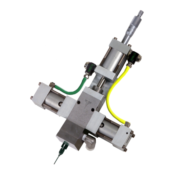
Patented meter and dispense system for precise one-component micro-dispensing.
Dispense Valve
2000 psi (14 MPa, 138 bar) Maximum Outlet Fluid Working Pressure
Metal Sleeves: 1200 psi (8 MPa, 83 bar) Maximum Material Inlet Pressure
Plastic Sleeves: 400 psi (2.8 MPa, 28 bar) Maximum Material Inlet Pressure
100 psi (0.7 MPa, 7 bar) Maximum Air Working Pressure
110°F (43°C) Maximum Ambient Temperature
150°F (65°C) Maximum Operating Temperature
Important Safety Instructions
Read all warnings and instructions in this
manual. Save these instructions.
Cycle Detection and Luer Lock Outlet Shown
332089C
EN
Advertisement
Table of Contents

Related Manuals for Graco Dispensit 1092


Summary of Contents for Graco Dispensit 1092
- Page 1 Operation - Maintenance Dispensit 1092 332089C Patented meter and dispense system for precise one-component micro-dispensing. Dispense Valve 2000 psi (14 MPa, 138 bar) Maximum Outlet Fluid Working Pressure Metal Sleeves: 1200 psi (8 MPa, 83 bar) Maximum Material Inlet Pressure Plastic Sleeves: 400 psi (2.8 MPa, 28 bar) Maximum Material Inlet Pressure 100 psi (0.7 MPa, 7 bar) Maximum Air Working Pressure 110°F (43°C) Maximum Ambient Temperature...
-
Page 2: Table Of Contents
Graco Standard Warranty ....38 Graco Information ......38... -
Page 3: 1092 Valve Models
1092 Valve Models 1092 Valve Models 1092 Valves Part No. Configuration Description A2A05051 VALVE, 1092-10A-2RS1-250-V-CD 1 inch stroke, 0.250 diameter rod, nitrided tool steel wetted components, cycle detect A2A05054 VALVE, 1092-10A-2RS1-375-V-CD 1 inch stroke, 0.375 diameter rod, nitrided tool steel wetted components, cycle detect A2A05057 VALVE, 1092-10A-2S1-MR.500-CD 1 inch stroke, 0.500 diameter rod, nitrided tool steel wetted... -
Page 4: Warnings
Warnings Warnings The following warnings are for the setup, use, grounding, maintenance, and repair of this equipment. The exclama- tion point symbol alerts you to a general warning and the hazard symbols refer to procedure-specific risks. When these symbols appear in the body of this manual or on warning labels, refer back to these Warnings. Product-specific hazard symbols and warnings not covered in this section may appear throughout the body of this manual where applicable. - Page 5 Warnings WARNING FIRE AND EXPLOSION HAZARD Flammable fumes, such as solvent and paint fumes, in work area can ignite or explode. Paint or solvent flowing through the equipment can cause static sparking. To help prevent fire and explosion: • Use equipment only in well-ventilated area. •...
-
Page 6: Important Isocyanate (Iso) Information
Important Isocyanate (ISO) Information Important Isocyanate (ISO) Information Isocyanate Conditions Keep Components A and B Separate Spraying or dispensing fluids that contain isocyanates creates potentially harmful mists, vapors, and Cross-contamination can result in cured material in atomized particulates. fluid lines which could cause serious injury or damage •... -
Page 7: Changing Materials
Important Isocyanate (ISO) Information Foam Resins with 245 fa Blowing Agents Some foam blowing agents will froth at temperatures above 90°F (33°C) when not under pressure, especially if agitated. To reduce frothing, minimize preheating in a circulation system. Changing Materials NOTICE Changing the material types used in your equipment requires special attention to avoid equipment damage... -
Page 8: Grounding
Grounding Grounding Overview This single-component meter and dispense device accurately meters liquid and semi-paste materials. The equipment must be grounded to reduce the risk The machine is ideal for a single-component application of static sparking. Static sparking can cause fumes to requiring very small and precise shots. -
Page 9: Optional Cycle Detection Sensors
Optional Cycle Detection Sensors Optional Cycle Detection h. PX-RET signal is made and Metering Rod is down (Dispense Material Complete). Sensors Solenoid-Open Spool Valve/EXTend is deacti- vated. The sensors are magnetic reed switches and must be Solenoid-Close Spool Valve/RETract is acti- connected to an electrical control package. -
Page 10: Component Identification
Component Identification Component Identification Typical System Configurations START HAND AUTO SW-2 PB-1 TR-1 SYSTEM AUXILIARY DISPENSE PRESSURE PRESSURE TIMER POWER REG-1 REG-2 SW-1/PL-1 Valve Liquid Control Top View of Controls Controls System shown with optional 4104A controls 332089C... -
Page 11: Typical Feed System Components
Component Identification Typical Feed System Components 5 Gallon Pail Cover 5 Gallon Pail Cover with Diaphragm with Diaphragm Pump Pump and Agitator 20 oz Cartridge Feed with Mounting Post 1 Gallon Ram and Pump WARNING DO NOT SERVICE WITHOUT REMOVING AIR PRESSURE AND WEARING SAFETY GLASSES. -
Page 12: Typical Feed System Components (Continued)
Component Identification Typical Feed System Components (continued) 5 Gallon Tank with Diaphragm Pump and Stand 5 Gallon Tank with 5:1 Pump and Stand 10 Gallon Tank with Diaphragm Pump, Agitator, 10 Gallon Tank with 5:1 Pump, Agitator, Vacuum, Vacuum, and Stand and Stand 332089C... -
Page 13: Metering Valve
Component Identification Metering Valve Key: Material Inlet Reload Air Inlet Grounding Lug Extend Air Flow Adjustment Spool Knob Metering Rod Retract Air Flow Adjustment Oil Cup Retaining Block Knob Extend Air Inlet Shot Size Locking Ring Retract Air Inlet Shot Size Adjuster Dispense Air Inlet Luer Lock Outlet 332089C... -
Page 14: Setup
Setup Setup NOTE: See Typical Installation diagram. 5. Connect each 1/4 in. outside diameter supplied air line to the corresponding control solenoid. See 3. Perform Setup procedure for feed system compo- Component Identification starting on page 10. nents. See feed system manual(s). 6. -
Page 15: Valve Mounting Diagram
Setup Valve Mounting Diagram As desired, use the following diagram to mount the metering valve. DIMENSION NON CYCLE DETECTION CYCLE DETECTION 8.38 9.13 4.19 4.56 SHOT SIZE ADJUSTMENT WITH LOCK 0.688 EXTEND ADJUSTABLE 0.688 FLOW CONTROL (2) #F (.257 DIA.) DRILL THRU WITH LOCK RETRACT ADJUSTABLE... -
Page 16: Startup
Startup Startup 1. Lubricate the metering rod port in the oil cup retain- ing block and fill the spool valve ports with compati- ble lubricant such as mesamoll or silicone oil. Metering Rod Port Spool Valve Ports . 7: Top View of Metering Valve with Top Section Removed 2. -
Page 17: Adjusting The Shot Size
Adjusting the Shot Size Adjusting the Shot Size 1. Rotate the shot size locking ring counterclockwise to loosen. 2. Rotate the shot size adjuster to adjust shot size. 3. Rotate the shot size locking ring clockwise to tighten. 4. Dispense into waste container to test shot size. 5. -
Page 18: Operation
Operation Operation The operation of the 1092 metering valve is controlled Step 2: Shift by an external source. If a 4104A Control Box was pur- chased, see the 4104A Control Box manual for opera- tion instructions. Sequence of Operation Step 1: Reload •... -
Page 19: Pressure Relief Procedure
4. Dispense 5 shots. Shots should be at least 75% of the full stroke. Air Dryer 5. Extend the metering rod into the tubes. If Graco Check the condition of the desiccant air dryer. Replace controls are provided with the system, see the as necessary. -
Page 20: Troubleshooting
Troubleshooting Troubleshooting Perform Pressure Relief Procedure before perform- ing any troubleshooting procedure. Problem Cause Solution Metering valve stalling and no mate- Blocked needle Check needle for cured material, rial being dispensed despite ade- replace as required quate input pressure Flow control valve closed Open needle Metering valve not discharging nor- Low material level in reservoirs... -
Page 21: Parts
Parts Parts 1092 Valve 1” CD 23, 24 332089C... - Page 22 Parts 1092 Valve Shared Components, 1” Stroke Part Description 120961 SCREW 61/2904-GN/11 TUBE 61/2904-YL/11 TUBE 82/0223/11 VALVE, cntl, flow 940170/99 FITTING, conn 94/0702/96 FITTING 94/0708/96 FITTING, tee, run 94/0740-B/99 CONNECTOR 95/0503/00 O-RING 95/0600/01 SEAL, u-cup 95/0849/11 SEAL, posipak 95/0903/00 O-RING, vit 95/0909/00 O-RING, vit 96/0332/99...
-
Page 23: 1092 Valve 1" Without Cd
Parts 1092 Valve 1” Without CD 332089C... - Page 24 Parts 1092 Valve Shared Components, 1” Stroke Part Description 120961 SCREW, shc 61/2904-GN/11 TUBE 61/2904-YL/11 TUBE 82/0223/11 VALVE, cntl, flow 94/0170/99 FITTING, conn 94/0702/96 FITTING 94/0708/96 FITTING, tee, run 94/0740-B/99 CONNECTOR 95/0503/00 O-RING, vit 95/0600/01 SEAL, u-cup 95/0601/01 SEAL, u-cup 95/0849/11 SEAL, posipak 95/0903/00...
-
Page 25: 1092 Valve 2" Cd
Parts 1092 Valve 2” CD 332089C... - Page 26 Parts 1092 Valve Shared Components, 2” Stroke Part Description 01/2702/97 PISTON, air cyl, rod, pd 120961 SCREW, shc 61/2904-GN/11 TUBE 61/2904-YL/11 TUBE 82/0223/11 VALVE, cntl, flow 84/1050-1200/11 LABEL, decal 94/0170/99 FITTING, conn 94/0702-PL/96 CONNECTOR 94/0708-PL/96 FITTING, tee, run 94/0740-B/99 CONNECTOR 95/0601/01 SEAL, u-cp 95/0849/11...
-
Page 27: 1092 Valve 2" Without Cd
Parts 1092 Valve 2” Without CD 332089C... - Page 28 Parts 1092 Valve Shared Components, 2” Stroke Part Description 120961 SCREW, shc 61/2904-GN/11 TUBE 61/2904-YL/11 TUBE 82/0223/11 VALVE, cntl, flow 84/1050-1200/11 LABEL, decal 94/0702/96 FITTING 94/0708/96 FITTING, tee, run 95/0601/01 SEAL, u-cp 95/0849/11 SEAL, posipak 95/0903/00 O-RING, vit 95/0909/00 O-RING, vit A2000006 CUP, 1092, seal plate A2000007...
-
Page 29: 1092 Valve 3" Cd
Parts 1092 Valve 3” CD 332089C... - Page 30 Parts 1092 Valve Components, 3” Stroke CD Part Description 01/2702/97 PISTON, air cyl, rod 120961 SCREW, shc 82/0223/11 VALVE, cntl, flow 84/1050-1200/11 LABEL, decal, mat’l, max, bar, clear 95/0502/00 O-RING, vit 95/0601/01 SEAL, u-cp 95/0605/01 SEAL, u-cup 95/0849/11 SEAL, posipak 95/0873/11 SEAL, pospk 95/0903/00...
-
Page 31: 1092 Valve 3" Without Cd
Parts 1092 Valve 3” Without CD 332089C... - Page 32 Parts 1092 Valve Shared Components, 3” Stroke Part Description 127627 SCREW 61/2904-GN/11 TUBE 61/2904-YL/11 TUBE 82/0223/11 VALVE, cntl, flow 84/0200-K3/11 LUBRICANT, grease, krytox 84/1050-1200/11 LABEL, decal, mat’l, max, bar, clear 94/0170/99 FITTING, conn 94/0702-PL/96 CONNECTOR 94/0708-PL/96 FITTING, tee 94/0740-B/99 CONNECTOR 95/0503/00 O-RING, vit 95/0601/01...
-
Page 33: Rebuild
Rebuild Rebuild Disassembly 13. Remove the two Spool Shift Pistons (21) from the End Caps (19). They should come out easily but if not use low pressure (less than 2 psi or 0.1 bar) air at the Tee Fitting (17) to move them. Remove the U-cup seals (4) from the Spool Shift Pistons (21). -
Page 34: Assembly
Rebuild Assembly 7. Install the Seal Cup (12) into the Divorced Section (10) over the Metering Rod (11) and slide the lubri- cated Posipak Seal (13) over the Metering Rod keeping the O-ring side of the Posipak facing down. The ends of the Metering Rod (11) should be pro- jecting from the upper and lower ends of the Divorced Section. - Page 35 Rebuild 18. Slide the Metering Rod (11) into the key slot on the piston and slide the Drive Cylinder End Cap Assem- bly (2) down onto the Divorced Section (10) and carefully over the O-ring (5). 19. Align the screw holes in the Drive Cylinder End Cap Assembly (2) with the corresponding holes in the Divorced Section (10) and install the four Screws (1).
-
Page 36: Electrical Requirements (Cycle Detection Option)
Electrical Requirements (Cycle Detection Option) Electrical Requirements (Cycle Detection Option) LABEL PX-EXT 9' CABLE BROWN (+24DC) WHITE (SIGNAL) SHOT SIZE ADJUSTMENT WITH LOCK LABEL PX-RET EXTEND 9' CABLE ADJUSTABLE BROWN (+24DC) FLOW CONTROL WHITE (SIGNAL) WITH LOCK RETRACT ADJUSTABLE FLOW CONTROL WITH LOCK GROUND STUD GREEN... -
Page 37: Technical Data
Wetted Parts ........Metering Valve: Hardened steel, 303/304, 404, UHM- WPE, Tungsten, carbide, fluoroelastomer, EPDM, PTFE, Acetal Graco-supplied Feed System Hoses and Fittings: Mild steel, 303/304, PTFE, buna, polyethylene, polypropyl- Graco-supplied Tanks: Polyethylene, 303/304, mild steel... -
Page 38: Graco Standard Warranty
With the exception of any special, extended, or limited warranty published by Graco, Graco will, for a period of twelve months from the date of sale, repair or replace any part of the equipment determined by Graco to be defective.