Graco PD44 Operations & Parts List
Metering valve for high wear material
Hide thumbs
Also See for PD44:
- Setup and operation (48 pages) ,
- Operation & maintenance manual (42 pages) ,
- Instructions manual (36 pages)
Table of Contents
Advertisement
Quick Links
Operation - Parts
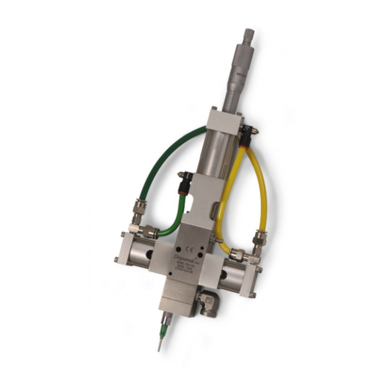
PD44 Metering Valve
for High Wear Material
Meter, mix, and dispense valve for precise, two-component micro-dispensing of high wear
material. For professional use only.
Part No. UA0421
See page 3 for model information, including maximum
working pressures.
Important Safety Instructions
Read all warnings and instructions in this
manual and in all related manuals before
using the equipment. Save all
instructions.
3A7284B
EN
Advertisement
Table of Contents

Related Manuals for Graco PD44


Summary of Contents for Graco PD44
- Page 1 Operation - Parts PD44 Metering Valve for High Wear Material 3A7284B Meter, mix, and dispense valve for precise, two-component micro-dispensing of high wear material. For professional use only. Part No. UA0421 See page 3 for model information, including maximum working pressures.
-
Page 2: Table Of Contents
Ratio Check....... 17 Graco Standard Warranty ....42 Operation. -
Page 3: Related Manuals
UA0421 2000 (14, 138) 100 (07, 7) 1200 (8, 83) 400 (2.8, 28) Motor Driven* The UA0421 model of the PD44 metering valve does not include a motor. You will need to supply a motor to operate the valve. 3A7284B... -
Page 4: Warnings
Warnings Warnings The following warnings are for the setup, use, grounding, maintenance, and repair of this equipment. The exclamation point symbol alerts you to a general warning and the hazard symbols refer to procedure-specific risks. When these symbols appear in the body of this manual or on warning labels, refer back to these Warnings. Product-specific hazard symbols and warnings not covered in this section may appear throughout the body of this manual where applicable. - Page 5 Warnings WARNING FIRE AND EXPLOSION HAZARD Flammable fumes, such as solvent and paint fumes, in work area can ignite or explode. Paint or solvent flowing through the equipment can cause static sparking. To help prevent fire and explosion: • Use equipment only in well-ventilated area. •...
- Page 6 Warnings WARNING MOVING PARTS HAZARD Moving parts can pinch, cut or amputate fingers and other body parts. • Keep clear of moving parts. • Do not operate equipment with protective guards or covers removed. • Equipment can start without warning. Before checking, moving, or servicing equipment, follow the Pressure Relief Procedure and disconnect all power sources.
-
Page 7: Important Iscocyanate (Iso) Information
Important Iscocyanate (ISO) Information Important Iscocyanate (ISO) Information Isocyanate Conditions Keep Components A and B Separate Spraying or dispensing fluids that contain isocyanates creates potentially harmful mists, vapors, and atomized particulates. Cross-contamination can result in cured material in fluid lines which could cause serious injury or damage •... -
Page 8: Changing Materials
Important Iscocyanate (ISO) Information Changing Materials NOTICE Changing the material types used in your equipment requires special attention to avoid equipment damage and downtime. • When changing materials, flush the equipment multiple times to ensure it is thoroughly clean. • Always clean the fluid inlet strainers after flushing. •... -
Page 9: Overview
(C) to a true earth ground. See Motor Driven PD44 Metering Valve on page 10. The complete system is enclosed. Mixing of the two materials takes place only in the mixer at the final stage Fluid hoses: use only electrically conductive hoses with of metering valve operation. -
Page 10: Component Identification
Home Proximity Switch Spool Assemblies Spool Valve Proximity Switch Metering Rods Motor (not included) Retaining Block Main Air Inlet/Control Dispense Air Inlet Solenoid (on far side of valve Reload Air Inlet as shown) . 1: PD44 Metering Valve Component Identification 3A7284B... -
Page 11: Typical System Configuration
Component Identification Typical System Configuration CONTROL POWER Liquid Control Corp. NORTH CANTON, OH 44720 USA 8400 PORT JACKSON AVE. N.W. SERIAL MODEL NUMBER NUMBER . 2: Typical Configuration Key: AA A Side Supply Pump AG A Side Air Shut-Off/Bleed Valve (Required) AB B Side Supply Pump AH Metering Valve Air Shut-Off/Bleed Valve (Required) AC Metering Valve - Included in Part No. -
Page 12: Typical Feed System Components
Component Identification Typical Feed System Components 5 Gallon Pail Cover 5 Gallon Pail Cover with Diaphragm with Diaphragm Pump Pump and Agitator 20 oz Cartridge Feed with Mounting Post 1 Gallon Ram and Pump WARNING DO NOT SERVICE WITHOUT REMOVING AIR PRESSURE AND WEARING SAFETY GLASSES. -
Page 13: Setup
Setup Setup NOTE: Refer to the Typical Installation diagram below. 1. Perform the Setup procedure for the supply pumps. Refer to the manual for the supply pumps you are All electrical wiring must be done by a qualified elec- using. See Related Manuals on page 3. trician and comply with all local codes and regula- tions. -
Page 14: Pd44 Metering Valve Mounting Diagram
3.75 Bottom View (Spool Assembly Not Shown) . 5: Mounting the Metering Valve Motor Mounting Diagram Use the following diagram to install a non-Graco motor onto the motor driven PD44 metering valve. See Technical Specifications, page 40. 2.22 2.039 0.182 0.182... -
Page 15: Custom Drive Mounting Diagram
Setup Custom Drive Mounting Diagram If using a non-Graco lead screw or housing, use the following diagram to ensure that the guide rods will align properly with the custom housing. 2X #30 (0.129Ø) 1.56 FLAT BTTM DRILL X .25 DP 1.75... -
Page 16: Startup
Startup Startup 3. Pressurize the A and B fluid supply pumps (AA, AB) connected to the metering valve (AC) to prime the system. See Model Information on page 3 for max- imum inlet working pressures. 1. Fill the spool valve ports with compatible lubricant. 4. -
Page 17: Ratio Check
Static Mixer . 11: Remove Static Mixer 3. Install the ratio check nozzle that is shipped with the PD44 metering valve. See Figure 12. 4. Dispense into a waste container to prime the ratio check nozzle. 3A7284B... -
Page 18: Operation
Operation Operation Step 3: Dispense The operation of the PD44 metering valve is controlled by an external source. Sequence of Operation Step 1: Reload • Metering rods (E) extend • A and B materials are simultaneously dispensed from the metering chamber into the disposable mixer •... -
Page 19: Pressure Relief Procedure
Pressure Relief Procedure Pressure Relief Shutdown Procedure Follow the Pressure Relief Procedure whenever you see this symbol. 1. Perform the Pressure Relief Procedure. 2. Inspect the metering rods (E) for material buildup. Clean as necessary. 3. Install the storage cap on the outlet nose (L). This equipment stays pressurized until pressure is manually relieved. -
Page 20: Maintenance
Maintenance Maintenance Perform the following procedures once a shift. NOTE: If material is leaking, see Troubleshooting on page 21. Material Reservoirs Check material levels and refill as necessary. Ensure that the material reservoirs are properly vented. Air Dryer Check the condition of the desiccant air dryer. Replace as necessary. -
Page 21: Troubleshooting
Troubleshooting Troubleshooting 1. Follow the Pressure Relief Procedure on page 19, before checking or repairing the PD44. 2. Check all possible problems and causes before disassembling the metering valve. Problem Cause Solution Metering valve stalling and no mate- Blocked mixer... -
Page 22: Rebuild
Rebuild Rebuild Wetted Section Disassembly 6. Loosen the set screws on top of the connecting block. 7. Slide the metering rod retaining plate until the larger hole position is in-line with the metering rod. See the following step. 8. Once the metering rod plate is in position, manually 1. - Page 23 Rebuild 11. Remove the four cap screws located at the top of 14. Remove the two tubes. Always keep the rods and the retaining block. tubes together as they are a matched set. Retaining Block Tube 15. Remove the protruding cap screws on each spool block.
-
Page 24: Spool Valve Rebuild
Rebuild Spool Valve Rebuild 5. Install the new u-cup seal on the piston. 6. Insert the new o-ring into the spool air cylinder end 1. Perform the Wetted Section Disassembly, page cap. 7. Install the proximity switch. 2. Remove the two cap screws. 8. -
Page 25: Wetted Section Rebuild
Rebuild Wetted Section Rebuild 5. Clean all wetted components thoroughly with com- patible solvent. 1. Perform the Wetted Section Disassembly, page 6. For each pneumatic drive spool block, install new zap seals and o-rings onto the o-ring retainer. 2. Remove the spool rods and sleeves from the meter- ing block. - Page 26 Rebuild 11. Carefully install the spool sleeves into the metering 14. Install the new zap seal in the metering tube sleeve block. Make sure the notched edge will align with with the spring facing down or toward the material the pin in the metering block and not cut the spool pressure side of the sleeve.
-
Page 27: Wetted Section Reassembly
Rebuild Wetted Section Reassembly 5. Install the drive assembly to the guides. 1. See the Wetted Section Disassembly, page 22. 2. Install the pneumatic spool rod drive. Apply purple thread locker to fasteners. Torque the fasteners to 67-70 in-lb (7.5-7.9 N•m). 6. - Page 28 Rebuild 12. Install the rear tie plate and cap screws. Rear Tie Plate Cap Screws 13. Install the material inlet blocks with the new o-rings. Material Inlet Block O-Ring 14. Install the material nose assembly with the new o-rings. O-Rings Nose 15.
- Page 29 Rebuild NOTES: 3A7284B...
-
Page 30: Parts
Parts Parts Stepper Motor Drive Body 17(x4) 22(x4) 32(x2) 10(x4) 32(x3) 10(x4) 32(x3) 4(x4) Press bearing (14) onto lead screw drive nut (15). Secure with retaining ring (13). Use blue thread locker (33) on item (9). Torque fastener to 26-30 in-lb (2.9-3.4 N•m). Install plunger (6) and retainer (8) onto block (7). - Page 31 NUT, LEADSCREW, DRIVE, STPR/SRVO 18A850 SCREW, LEADSCREW, DRIVE, STPR/SRVO GC2188 SCREW, SHDC, SS, .190 X .500 01/2991-1/97 COUPLER, LDSCRW, PD44, 1/4, MTR, SHFT 128410 SCREW, SHCS, 6-32 X .375 130865 FASTENER, SHS, 6-32 X .31, CUP PT, SS 01/2890/97 PLATE, PLATE, MTG, STPR, PD44, REM 96/0187/98 SCREW, SHC, 8-32 X 0.38, SS...
-
Page 32: Metering Rod And Spool Valve
Parts Metering Rod and Spool Valve Set Screw Connecting Plate 101a Slide Plate 101b 101c 101a Use Krytox lubricant to install o-rings (102) on metering tubes. 103 Use mineral oil lubricant on seals, rods, and counterbores. Front Install seals into counterbores springs downs. -
Page 33: High Viscosity Spool Valve
Parts High Viscosity Spool Valve MODEL NUMBER PD44C-ABCDEFGHIJKLMNOPQRSTUVWX MAX FLUID WPR XXXX Mpa XXXX XXXX MAX AIR WPR 0.7 Mpa 7 100 PSI SERIAL SERIES UA1234 NF09A 203 207 Apply purple thread locker to threads. Torque to 22-26 in-lbs (2.5-2.9 N*m). . -
Page 34: Spool Air Piston Assembly
. 16: Spool Air Piston Part Description 123453 FITTING, 1/4 tube x 1/8 npt, male 18A848 CAP, end, air cylinder, spool, pd44, 1/4 npt 95/0504/01 O-RING, buna, 028, 70a 01/2973/97 CYLINDER, cylinder, air, spool, pd, 1.5 01/2976/97 PISTON, air cylinder, spool, pd, 1.5 b... -
Page 35: Material Inlet Blocks
402b 404a Torque to 22-26in-lb (2.5-2.9 N•m). . 17: Material Inlet Blocks Part Description 02/2995-S/25 KIT, inlet, pd44, top, 1/4 npt, lh, ss 402a 16A570 BLOCK, pd44, top inlet, 1/4 npt, ss 402b 96/0097/98 SCREW, socket head, #10-24x1.25, SST 403... -
Page 36: Standard Nose With 7/8-9 Thread
Parts Standard Nose with 7/8-9 Thread 503(x2) 505(x2) 7/8-9 Thread . 18: Standard Metering Valve Nose Quantity Large Port A, Large Port A, Part Description Large Port B Small Port B 01/2726/98 BLOCK, nose 01/2723/98 BLOCK, nose 503 O-RING 96/0125/98 SCREW, shc, 10-24 x 0.50, SST 60/0137/89 NUT, retaining, 3/16”, 1/4”, &... -
Page 37: Accessories
Accessories Accessories Static Mixer Kits with Shroud Part Description 964034 Mixer, Kit, 3/16 in. (4.8mm) x 24, 10 taper tip mixers with shroud 964032 Mixer, Kit, 3/16 in. (4.8mm) x 32, 10 taper tip mixers with shroud 964028 Mixer, Kit, 3/16 in. (4.8mm) x 32, 10 Luer Lock tip mixers with shroud/sleeve 964033 Mixer, Kit, 1/4 in. - Page 38 Accessories Needles Part Description E4000025-50 Needle, Luer Lock, Sampler Package (10 each 14 ga x 1/2 in., 16 ga x 1/2 in., 18 ga x 1/2 in., 20 ga x 1/2 in., 22 ga x 1/2 in.) E4000001-50 Needle, Luer Lock, 14 Gauge x 1/2 in., 50 Pack E4000004-50 Needle, Luer Lock, 15 Gauge x 1/2 in.,...
-
Page 39: Electrical Requirements
Electrical Requirements Electrical Requirements PD44 Metering Valve: The wiring harness sensors are 24 VDC normally open PNP. . 19 3A7284B... -
Page 40: Technical Specifications
Ratio Range (depending on metering rods 1:1 to 25:1 selected) Maximum Cycle Rate (application dependent) Up to 15 cycles per minute (with standard Graco motor) Dimensions (H x L x W), height to end of material inlet block Motor-driven with Graco Motor 17.5 x 4.13 x 7.57 in. -
Page 41: California Proposition 65
Technical Specifications Motor Specifications If a non-Graco motor is used with the Motor Driven Torque at Maximum Speed: 117 oz-in (7.3 in-lb) at 20 PD44 Metering Valve, it must meet the following specifi- revolutions per second (1 in. of rod travel per second). -
Page 42: Graco Standard Warranty
With the exception of any special, extended, or limited warranty published by Graco, Graco will, for a period of twelve months from the date of sale, repair or replace any part of the equipment determined by Graco to be defective.