Table of Contents
Advertisement
Quick Links
Operation - Maintenance
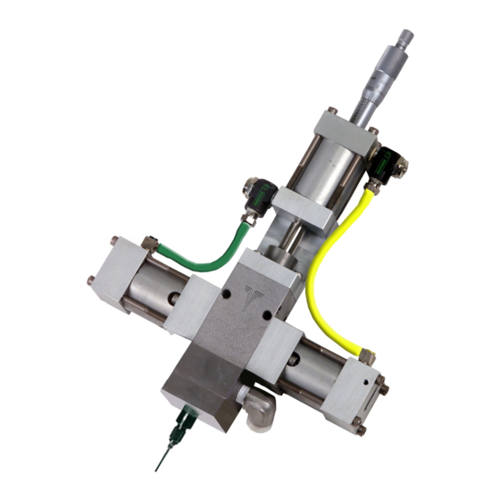
Dispensit
1052
Patented meter and dispense system for precise one-component micro-dispensing. Not
for use in explosive atmospheres.
2000 psi (14 MPa, 138 bar) Maximum Outlet Fluid Working Pressure
Metal Sleeves: 1200 psi (8 MPa, 83 bar) Maximum Material Inlet Pressure
Plastic Sleeves: 400 psi (2.8 MPa, 28 bar) Maximum Material Inlet Pressure
100 psi (0.7 MPa, 7 bar) Maximum Air Working Pressure
110°F (43°C) Maximum Ambient Temperature
150°F (65°C) Maximum Operating Temperature
Important Safety Instructions
Read all warnings and instructions in this
manual. Save these instructions.
Cycle Detection and Luer Lock Outlet Shown
3A0231F
EN
Advertisement
Table of Contents

Related Manuals for Graco Dispensit 1052


Summary of Contents for Graco Dispensit 1052
- Page 1 Operation - Maintenance Dispensit 1052 3A0231F Patented meter and dispense system for precise one-component micro-dispensing. Not for use in explosive atmospheres. 2000 psi (14 MPa, 138 bar) Maximum Outlet Fluid Working Pressure Metal Sleeves: 1200 psi (8 MPa, 83 bar) Maximum Material Inlet Pressure Plastic Sleeves: 400 psi (2.8 MPa, 28 bar) Maximum Material Inlet Pressure 100 psi (0.7 MPa, 7 bar) Maximum Air Working Pressure 110°F (43°C) Maximum Ambient Temperature...
-
Page 2: Table Of Contents
Graco Ohio Standard Warranty ....30 Graco Ohio Information ....30... -
Page 3: 1052 Valve Modes
1052 Valve Modes 1052 Valve Modes 1052 Valves Part No. Configuration Description A2A03085 1052-10A-2RS1-062-V 1 Inch 1 inch storke, 0.062 diameter rod, nitrided tool steel wetted components A2A03073 1052-10A-2RS1-125-V 1 Inch 1 inch storke, 0.125 diameter rod, nitrided tool steel wetted components A2A03010 1052-10A-2RS1-188-V 1 Inch... -
Page 4: Warnings
Warnings Warnings The following warnings are for the setup, use, grounding, maintenance, and repair of this equipment. The exclama- tion point symbol alerts you to a general warning and the hazard symbol refers to procedure-specific risk. Refer back to these warnings. Additional, product-specific warnings may be found throughout the body of this manual where applicable. - Page 5 Warnings WARNING ELECTRIC SHOCK HAZARD This equipment must be grounded. Improper grounding, setup, or usage of the system can cause elec- tric shock. • Turn off and disconnect power cord before servicing equipment. • Use only grounded electrical outlets. • Use only 3-wire extension cords.
-
Page 6: Isocyanate Conditions
Isocyanate Conditions Isocyanate Conditions • Keep the ISO lube pump reservoir (if installed) filled with Graco Throat Seal Liquid (TSL), Part 206995. The lubricant creates a barrier between the ISO and the atmosphere. Spraying or dispensing materials containing isocya- •... -
Page 7: Grounding
Grounding Grounding Optional Cycle Detection Spool Sensors The spool sensors are magnetic reed switches and must be connected to an electrical control. An LED on the switch illuminates to indicate the shifting of the This product must be grounded. In the event of an elec- spool. - Page 8 Optional Cycle Detection Spool Sensors d. PX-EXT and PX-CSV signal drops off. e. Spool shifts from the Reload Position to the Dis- pense Position. PX-OSV signal is made. g. Metering Rod Extends downward (Dispensing Material). h. PX-RET signal is made and Metering Rod is down (Dispense Material Complete).
-
Page 9: Component Identification
Component Identification Component Identification Typical System Configurations START HAND AUTO SW-2 PB-1 TR-1 SYSTEM AUXILIARY DISPENSE PRESSURE PRESSURE TIMER POWER REG-1 REG-2 SW-1/PL-1 Valve Liquid Control Top View of Controls Controls System shown with optional 4104A controls 3A0231F... -
Page 10: Typical Feed System Components
Component Identification Typical Feed System Components 5 Gallon Pail Cover 5 Gallon Pail Cover with Diaphragm with Diaphragm Pump Pump and Agitator 20 oz Cartridge Feed with Mounting Post 1 Gallon Ram and Pump WARNING DO NOT SERVICE WITHOUT REMOVING AIR PRESSURE AND WEARING SAFETY GLASSES. -
Page 11: Typical Feed System Components (Continued)
Component Identification Typical Feed System Components (continued) 5 Gallon Tank with Diaphragm Pump and Stand 5 Gallon Tank with 5:1 Pump and Stand 10 Gallon Tank with Diaphragm Pump, Agitator, 10 Gallon Tank with 5:1 Pump, Agitator, Vacuum, Vacuum, and Stand and Stand 3A0231F... -
Page 12: Metering Valve
Component Identification Metering Valve Key: Material Inlet Reload Air Inlet Grounding Lug Extend Air Flow Adjustment Spool Knob Metering Rod Retract Air Flow Adjustment Oil Cup Retaining Block Knob Extend Air Inlet Shot Size Locking Ring Retract Air Inlet Shot Size Adjuster Dispense Air Inlet Needle 3A0231F... -
Page 13: Setup
Setup Setup NOTE: See Typical Installation diagram. 5. Connect each 1/4 in. outside diameter supplied air line to the corresponding control solenoid. See 3. Perform Setup procedure for feed system compo- Component Identification starting on page 9. nents. See feed system manual(s). 6. -
Page 14: Valve Mounting Diagram
Setup Valve Mounting Diagram As desired, use the following diagram to mount the metering valve. 1.250 .937 .625 .377 .313 Ø.312 C-BORE FOR 95/0503/00 O-RING (2) PLACES 1.250 1.062 OUT IN .625 Ø.126/.128 X .25 DP .188 FOR 1/8 DOWEL PINS (2) PLACES 8-32 X .38 DP - OPTIONAL... -
Page 15: Startup
Startup Startup 1. Lubricate the metering rod port in the oil cup retain- ing block and fill the spool valve ports with compati- ble lubricant such as mesamoll or silicone oil. Metering Rod Port Spool Valve Ports . 7: Top View of Metering Valve with Top Section Removed 2. -
Page 16: Adjusting The Shot Size
Adjusting the Shot Size Adjusting the Shot Size 1. Rotate the shot size locking ring counterclockwise to loosen. 2. Rotate the shot size adjuster to adjust shot size. 3. Rotate the shot size locking ring clockwise to tighten. 4. Dispense into waste container to test shot size. 5. -
Page 17: Operation
Operation Operation Step 2: Shift The operation of the 1052 metering valve is controlled by an external source. If a 4104A Control Box was pur- chased, see the 4104A Control Box manual for opera- tion instructions. Sequence of Operation Step 1: Reload •... -
Page 18: Pressure Relief Procedure
4. Dispense 5 shots. Shots should be at least 75% of the full stroke. Air Dryer 5. Extend the metering rod into the tubes. If Graco Check the condition of the desiccant air dryer. Replace controls are provided with the system, see the as necessary. -
Page 19: Troubleshooting
Troubleshooting Troubleshooting Perform Pressure Relief Procedure before perform- ing any troubleshooting procedure. Problem Cause Solution Metering valve stalling and no mate- Blocked needle Check needle for cured material, rial being dispensed despite ade- replace as required quate input pressure Flow control valve closed Open needle Metering valve not discharging nor- Low material level in reservoirs... -
Page 20: Electrical Requirements
Electrical Requirements Electrical Requirements Electrical requirements for 1052-10A shown. 3A0231F... -
Page 21: Parts
Parts Parts Non Cycle Detect 3A0231F... - Page 22 Parts 1052 Valve Shared Components Ref No. Part No. Description Qty. 24P096 KIT, installation, sleeve 61/2904-GN/11 TUBE 61/2904-YL/11 TUBE 82/0228-1/11 VALVE, CNTL, flow 94/0170/99 FITTING, conn 94/0740-B/99 CONNECTOR 95/0017/00 O-RING, vit 95/0021/01 O-RING, buna 95/0503/00 O-RING, vit 95/0515/00 O-RING, vit 95/0603/01 SEAL, u-cup 95/0604/01...
-
Page 23: Cycle Detect
Parts Cycle Detect 3A0231F... - Page 24 Parts 1052 Cycle Detect Valve Shared Components Ref No. Part No. Description Qty. 24P096 KIT, installation sleeve 61/2904-GN/11 TUBE 61/2904-YL/11 TUBE 82/0228-1/11 VALVE, cntl 94/0170/99 FITTING, conn 94/0740-B/99 CONNECTOR 95/0017/00 O-RING, vit 95/0021/01 O-RING, buna 95/0503/00 O-RING, vit 95/0515/00 O-RING, vit 95/0603/01 SEAL, u-cup 95/0604/01...
-
Page 25: 1052 Standard Inlet/Outlet Needle Block
Parts 1052 Standard Inlet/Outlet Needle Block Ref No. Part No. Description Qty. 94/1527/98 FITTING, elbw, strt 95/0904/00 O-RING, vit A2000148 BLOCK, ndl, single A2000164 BLOCK, inlet A2000271 GASKET, tef / fgls B3500008 SCREW, shc B3500026 SCREW, shc E4000016 ADAPTER, ndl J1000002 PIN, roll 3A0231F... -
Page 26: Rebuild
Rebuild Rebuild Disassembly 13. Remove the two Spool Shift Pistons (21) from the End Caps (19). They should come out easily but if not use low pressure (less than 2 psi or 0.1 bar) air at the Tee Fitting (17) to move them. Remove the U-cup seals (4) from the Spool Shift Pistons (21). -
Page 27: Assembly
Rebuild Assembly 7. Install the Seal Cup (12) into the Divorced Section (10) over the Metering Rod (11) and slide the lubri- cated Posipak Seal (13) over the Metering Rod keeping the O-ring side of the Posipak facing down. The ends of the Metering Rod (11) should be pro- jecting from the upper and lower ends of the Divorced Section. - Page 28 Rebuild 18. Slide the Metering Rod (11) into the key slot on the piston and slide the Drive Cylinder End Cap Assem- bly (2) down onto the Divorced Section (10) and carefully over the O-ring (5). 19. Align the screw holes in the Drive Cylinder End Cap Assembly (2) with the corresponding holes in the Divorced Section (10) and install the four Screws (1).
-
Page 29: Technical Data
Wetted Parts........Metering Valve: Hardened steel, 303/304, 404, UHM- WPE, Tungsten, carbide, fluoroelastomer, EPDM, PTFE, Acetal Graco-supplied Feed System Hoses and Fittings: Mild steel, 303/304, PTFE, buna, polyethylene, polypropyl- Graco-supplied Tanks: Polyethylene, 303/304, mild steel... -
Page 30: Graco Ohio Standard Warranty
With the exception of any special, extended, or limited warranty published by Graco, Graco will, for a period of twelve months from the date of sale, repair or replace any part of the equipment determined by Graco to be defective.