Table of Contents
Advertisement
Quick Links
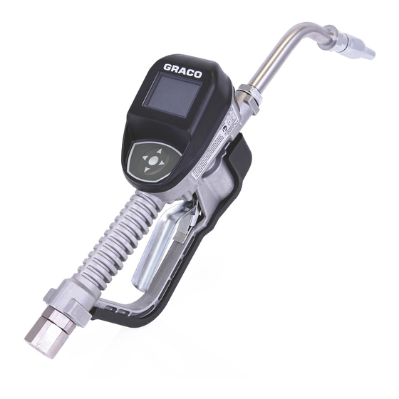
Installation and Operation
SDP8/SDP18 Preset
Metered Dispense Valve
Pulse FC Enabled
For dispensing oil, automatic transmission fluid (ATF), gear oils, and antifreeze.
Not approved for use in explosive atmospheres or hazardous locations. For professional
use only.
See page 6 for model information.
1500 psi (10 MPa, 103 bar) Maximum Working Pressure
Important Safety
Instructions
Read all warnings and instructions
in this manual and related system
manuals before using the
equipment. Save all instructions.
NOTICE
The metered dispense valve is designed to
dispense petroleum-based lubricants, and
antifreeze only. Brake cleaner and/or harsh
solvents may damage the plastic
components.
3A6673B
EN
Advertisement
Table of Contents

Related Manuals for Graco SDP8 Series


Summary of Contents for Graco SDP8 Series
- Page 1 Installation and Operation SDP8/SDP18 Preset Metered Dispense Valve 3A6673B Pulse FC Enabled For dispensing oil, automatic transmission fluid (ATF), gear oils, and antifreeze. Not approved for use in explosive atmospheres or hazardous locations. For professional use only. See page 6 for model information. 1500 psi (10 MPa, 103 bar) Maximum Working Pressure Important Safety Instructions...
-
Page 2: Table Of Contents
Contents Contents Warnings ....................4 Models ......................6 Overview ....................7 Metered Dispense Valve ...............7 Navigation Pad (F . 1) .................7 Locking and Unlocking the Trigger ............7 Opening and Closing the Nozzle ............8 Typical Installation ..................9 Mounting Bracket ..................9 Oil Bar ....................9 Installation ....................10 Pressure Relief Procedure ..............10 Grounding ...................10 Pre-Installation Procedure ..............10... - Page 3 FCC / IC Notice ........42 Graco 5-Year Meter and Valve Warranty ..........43...
-
Page 4: Warnings
Warnings Warnings The following warnings are for the setup, use, grounding, maintenance, and repair of this equipment. The exclamation point symbol alerts you to a general warning and the hazard symbols refer to procedure-specific risks. When these symbols appear in the body of this manual or on warning labels, refer back to these Warnings. - Page 5 Warnings WARNING FIRE AND EXPLOSION HAZARD When flammable fluids are present in the work area, such as gasoline and wind- shield wiper fluid, be aware that flammable fumes can ignite or explode. To help prevent fire and explosion: • Use equipment only in well-ventilated area. •...
-
Page 6: Models
Models Models Max Volumetric Flow Rate Model Swivel Extension Nozzle Fluid 26C384 1/2 NPT Rigid Automatic 26C385 1/2 NPT Rigid Antifreeze Antifreeze 26C354 1/2 NPT Flexible Automatic 26C355 1/2 NPT Flexible Antifreeze Antifreeze 26C356 1/2 NPT Rigid High Flow 26C357 1/2 NPT Flexible High Flow... -
Page 7: Overview
Overview Overview Metered Dispense Valve Locking and Unlocking the Trigger NOTE: The metered dispense valve can be set up to be used without a Pulse FC system, or with a Pulse FC system with the installation of a Pulse FC Starter kit (P/N 26C401). Unlocked Display Navigation... -
Page 8: Opening And Closing The Nozzle
Overview Opening and Closing the Nozzle Open Closed • To open the nozzle, rotate the nozzle clockwise. • To close the nozzle, rotate the nozzle counter-clockwise. 3A6673B... -
Page 9: Typical Installation
It is not a complete system design. console. Contact your Graco distributor for assistance in designing a system to suit your needs. The metered dispense valve is not designed for in-line installation. -
Page 10: Installation
Installation Installation Pressure Relief Procedure FIRE HAZARD Conductive metal surfaces on the metered Follow the Pressure Relief dispense valve must not make contact with Procedure whenever you see this any positively charged metal surface, symbol. including (but not limited to), the starter solenoid terminal, alternator terminal or battery terminal. -
Page 11: Flushing
Installation Flushing Install the Metered Dispense Valve The equipment was tested with lightweight oil, which was left in the fluid passages to protect parts. To avoid contaminating the fluid, flush the equipment with a compatible solvent before use. Follow Pressure Relief Procedure, page 10. -
Page 12: Install The Extension Tube
Installation Install the Extension Tube With an open-end adjustable wrench on the flats of the nozzle bushing, tighten firmly (F . 10). Adjust nut (c) on extension (2) so that the maximum thread engagement of the extension can be utilized (F . -
Page 13: Preset Mode
Preset Mode Preset Mode This calibration procedure requires a one quart or one liter calibrated, volumetric flask. If a one quart or one liter calibrated, Main Menu Screen volumetric flask is not available, see Alternate Calibration instructions, page 16. This screen provides access to the main To calibrate the metered dispense valve: metered dispense valve functions: Use the UP or DOWN ARROW button on... - Page 14 Preset Mode Use the UP or DOWN ARROW button on Dispense exactly one quart or one liter of the keypad to highlight CALIBRATE (F fluid into the one quart or one liter clean, 14) and then press the center ENTER calibrated, volumetric flask.
-
Page 15: Manual Calibration
Preset Mode Press the center ENTER button on the The k-factor adjustment screen shown in keypad again to select END and save the . 20 displays. new calibration factor. After selecting END the following screen . 18) displays. . 20 Use the UP and DOWN ARROW to increase or decrease the displayed . -
Page 16: Alternate Calibration
Preset Mode Be sure ENTER is highlighted in the Record the volume displayed on the lower left corner of the display as shown metered dispense valve. Note this in F . 21. Press the center ENTER volume as the VOLUME DISPLAYED button on the keypad to save the new ON THE METERED DISPENSE VALVE calibration factor. - Page 17 Preset Mode Use the UP or DOWN ARROW button on The k-factor adjustment screen shown in the keypad to highlight CALIBRATE (F . 28 displays. 25) and then press the center ENTER button on the keypad to select the CALIBRATE option. .
-
Page 18: Dispense
Preset Mode DISPENSE 11. Calculate the new k-factor using the following equation: DISPENSE SCREEN Example: Kcurrent = 169 Volume displayed on metered dispense valve = 0.970 quart Volume dispensed = 1 quart PRESET ADJUSTMENT SCREEN Round to the nearest whole number: 163.9 = 164. -
Page 19: Preset Dispense
Preset Mode DISPENSED FLUID COUNTER- As fluid is Preset Dispense dispensed, this number increases to reflect Wake up the metered dispense valve by the quantity of fluid that is being dispensed. pressing any button on the key pad (F NOTE: If RESET was not selected after the 1, page 7). - Page 20 Preset Mode STOP Function The screen shown in F . 33 displays. Notice the word “DONE” near the top of During the dispense the word STOP (F . 32) the screen, confirming the requested is highlighted on the lower left corner of the PRESET amount of fluid has been dispense screen.
-
Page 21: Total
Preset Mode TOTAL When the screen is highlighted (F . 36), press the ENTER button on the key pad. . 35 LIFETIME TOTAL - Running, non-resettable . 36 total quantity fluid that has been dispensed over the life of the meter. The unit of mea- DEVICE INFORMATION surement displayed is determined by the Unit of Measurement criteria selected in... -
Page 22: Reset
Preset Mode RESET SET-UP SCREENS Restarts meter. After selecting RESET the The SET-UP Menu includes the following screen display goes blank. After options: UNIT OF MEASURE, BANNER, approximately 10 seconds the screens CALIBRATE and “+++”. shown in F . 38- F . - Page 23 Preset Mode UNIT OF MEASURE BANNER The meter is factory-set to quarts. The UNIT The banner screen is used to assign a name OF MEASURE screen configures the meter to the meter, such as Meter 1, Meter 2, etc. to dispense in PINTS, QUARTS, GALLONS This is useful in shops that have more than OR LITERS.
- Page 24 Preset Mode CALIBRATE LANGUAGE Calibrating the metered dispense valve The meter is factory-set to English. On the assures that dispenses are accurate. See first language screen it can be configured to Calibration instructions beginning on page display in ENGLISH, FRENCH, GERMAN, +++”...
- Page 25 Preset Mode PRESET TITLE - Identifies which preset PRESET option is being set up. The example in F The metered dispense valve can be 46 shows PRESET1. This means you are programmed to dispense 5 different preset setting up the PRESET parameters for PRE- amounts.
- Page 26 Preset Mode Press the center ENTER button on the keypad after each letter or number is highlighted to select it. After naming the PRESET, use the RIGHT ARROW button on the keypad to highlight the symbol. Press the center ENTER button on the keypad to return to the PRESET Setup Screen.
-
Page 27: Device Information
Preset Mode DEVICE INFORMATION See page 21 for a description of this screen. RESET See page 22 for a description of this screen. GO BACK Returns to the Main Menu Screen (F . 54). . 52 The menu shown in F . -
Page 28: Pulse Fc Mode
. 56 Tags may be purchased from Graco as packs of cards. When a tag or voucher is referenced After the meter has been successfully in this manual, it refers to a card programmed configured, the main menu screen to perform the designated function. -
Page 29: Activation
Pulse FC Mode Activation Calibrate the metered dispense valve for specific fluids at nominal flow rates. Press the center ENTER button on the This calibration procedure requires a one keypad to activate the meter. The screen quart or one liter calibrated, volumetric flask. shown in F . -
Page 30: Manual Calibration
Pulse FC Mode Dispense exactly one quart or one liter After selecting END the Main Menu of fluid into a one quart or one liter clean, screen displays. calibrated, volumetric flask. NOTE: During calibration dispense the metered dispense valve will not display the volume dispensed. -
Page 31: Dispense
Pulse FC Mode The k-factor adjustment screen shown in After selecting ENTER the Main Menu screen . 64 displays. shown in F . 66 displays. . 64 . 66 Use the UP and DOWN ARROW to DISPENSE increase or decrease the displayed k-factor until the new k-factor displays on Screen Identification the screen. - Page 32 Pulse FC Mode DISPENSED FLUID COUNTER- As fluid is The progress bar (F) fills-in and a dispensed, this number increases to reflect numeric percentage increases as the amount of fluid dispensed nears the the quantity of fluid that is being dispensed. Preset amount.
-
Page 33: Utility Menu
Pulse FC Mode UTILITY MENU Use the UP or DOWN ARROW button to select the desired screen from the list. There are three Utility options available from When the screen is highlighted, press the UTILITY MENU screen. the ENTER button on the key pad. •... - Page 34 Pulse FC Mode FLIP DISPLAY GO BACK Allows the data to be viewed on the metered Returns to the Main Menu Screen (F . 74). dispense valve display upside down for oil bar installation. After selecting FLIP DISPLAY, the meter display goes blank for about 10 seconds.
-
Page 35: Service
Service Service Battery Replacement Install 4 new batteries. See labels on the each side of the housing and F . 76 for battery orientation. • Replace batteries with four AA, alkaline batteries. • Be sure to follow the correct polarity as shown on the installation labels located on either side of the metered dispense valve when installing batteries in the... -
Page 36: Parts
Parts Parts . 78 3A6673B... -
Page 37: Parts
Parts Parts Related Kits Part Description VALVE, metered ---- dispense valve (see Ref Part Description models page X) KIT, Trip Rod Repair, includes ---- EXTENSION 25D903 27, 28, 29 16Y863 Flex KIT, Swivel Filter, includes 4 25D906 255194 Rigid and 10 255854... -
Page 38: Troubleshooting
Batteries are dead. Replace batteries, page 35. Electronic control is Replace the electronic bezel malfunctioning. assembly. Contact your Graco distributor for assistance ordering this part. Slow or no fluid flow Filter is clogged. Relieve pressure, page 10. Clean or replace filter. - Page 39 Troubleshooting Problem Cause Solution Metered dispense valve Poor seal at metering cover Contact your Graco leaks from cover/control chamber distributor for repair or replacement. Metered dispense valve Twist lock nozzle has a Replace nozzle. See Install leaks from twist lock nozzle.
-
Page 40: Error Codes
Solution Ensure that your flow rate is not higher Reed Switch Error: Error occurred with than 18 gpm (68 lpm). For further pick-up in internal gear. assistance, contact your Graco distributor. Reed switch malfunction. Replace electronic bezel housing. Error 2... -
Page 41: Technical Specifications
Technical Specifications Technical Specifications Metered Dispense Valve Metric Flow range* 0.25 to 18 gpm 0.9 to 68 lpm *Tested in 10W motor oil. Flow rates vary with fluid pressure, temperature and viscosity. Maximum Working Pressure 1500 psi 10.34 MPa, 103.4 bar Units of Measure (factory set to pints, quarts, gallons liters... -
Page 42: Fcc / Ic Notice
Technical Specifications FCC / IC Notice Contains FCC ID: JHI-SDPMETER Contains IC: 4840A-SDPMETER The enclosed device complies with Part 15 of the FCC Rules and with Industry Canada license-exempt RSS standard(s). Operation is subject to the following two conditions:(1) this device may not cause harmful interference and (2) this device must accept any interference received, including interference that may cause undesired operation. -
Page 43: Graco 5-Year Meter And Valve Warranty
With the exception of any special, extended, or limited warranty published by Graco, Graco will, for a period from the date of sale as defined in the table below, repair or replace equipment covered by this warranty and determined by Graco to be defective. - Page 44 Graco Headquarters: Minneapolis International Offices: Belgium, China, Japan, Korea GRACO INC. AND SUBSIDIARIES • P.O. BOX 1441 • MINNEAPOLIS MN 55440-1441 • USA Copyright 2019, Graco Inc. All Graco manufacturing locations are registered to ISO 9001. www.graco.com, Revision A, April 2019...