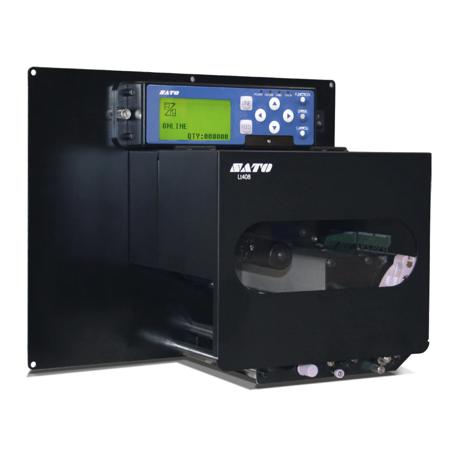
SATO LT408 Operator's Manual
Print engine
Hide thumbs
Also See for LT408:
- Operator's manual (110 pages) ,
- Parts list (43 pages) ,
- Specifications (2 pages)
Table of Contents
Advertisement
Advertisement
Table of Contents
Troubleshooting

Related Manuals for SATO LT408


Summary of Contents for SATO LT408
-
Page 1: Print Engine
Lt408 PRINT ENGINE OPERATOR MANUAL PN: 9001152A... - Page 2 SATO America, Inc. 10350A Nations Ford Road Charlotte, NC 28273 Main Phone: (704) 644.1650 Technical Support Hotline: (704) 644.1660 Technical Support Fax: (704) 644.1661 E-Mail: satosales@satoamerica.com technicalsupport@satoamerica.com www.satoamerica.com WARNING THE EQUIPMENT REFERENCED IN THIS DOCUMENT COMPLIES WITH THE REQUIREMENTS IN PART 15 OF FCC RULES FOR A CLASS B COMPUTING DEVICE.
-
Page 3: Table Of Contents
Operational Mode Selection Interface Selection RS232C High-Speed Serial Interface IEEE1284 Parallel Interface Universal Serial BUS (USB) Adapter Local Area Network (LAN) Ethernet 802.11b Wireless All Interfaces Accessories Installation Interface Installation Lt408 Operator Manual 3-11 3-12 3-12 3-13 3-16 3-23 3-23 PN: 9001152A... - Page 4 RS232 Serial Interface Universal Serial Bus (USB) Interface LAN Ethernet Interface Wireless LAN Interface Centronics Interface Test Print Troubleshooting Hex Dump Mode Test Label Printing Sample Test Label Lt408 Operator Manual 4-10 4-11 4-12 4-13 4-14 4-15 4-16 4-17 4-18...
- Page 5 Print Head Alignment Print Head Pressure Print Head Balance Ribbon Guide Label Sensor Positioning Operational Adjustments Volume Pitch Offset Darkness APPENDIX Session Connect/Disconnect Ready/Busy Timing Charts X-On/X-Off Timing Charts Printer Dimensions Glossary Lt408 Operator Manual 6-10 6-10 6-10 6-10 6-10 PN: 9001152A...
-
Page 6: Introduction
INTRODUCTION Lt408 Operator Manual • About This Manual • General Description • Control Features PN: 9001152A... - Page 7 This manual is laid out consistent with the product discussed and provides all of the information required for printer maintenance and repair by SATO approved personnel. For the repair technician, this manual is intended to compliment, and to be used as an extension of, owner/operator literature.
-
Page 8: General Description
Unit 1: Introduction GENERAL DESCRIPTION The SATO Lt408, OEM print engine has been designed and manufactured to meet the needs of the entry-level print apply market. The entry-level market can be generally defined as small to mid-sized manufacturers with low throughput, light-duty applications. - Page 9 Ribbon Rewind Spindle Ribbon Supply Spindle Ribbon Roller Print Head Latch Media Guide Front Platen Roller Feed Roller Dispenser Bar Pressure Plate Release Knob Print Head Release Knob Label Sensor Adjustment Knob Figure 1-1b, Primary Components Lt408 Operator Manual PN: 9001152A...
-
Page 10: Control Features
CONTROL FEATURES This chapter identifies the interactive control features of the printer. These functions are defined generally here. More specific explanations will be found throughout this manual on how to use them. LCD DISPLAY OPERATOR PANEL FEATURES POWER Illuminates green when the printer is powered on. Terminates when powered off. -
Page 11: Technical Data
TECHNICAL DATA Lt408 Operator Manual • Physical Characteristics • Power • Enviromental • Processing • Print • Media • Ribbon • Sensing • Interface Modules • Character Font Capabilities • Barcode Capabilities • Regulatory Approvals PN: 9001152A... - Page 12 15 to 85% RH Non-Condensing 32 Bit RISC 4 Megabytes 16 Megabytes 32 Kilobytes 2.95 Megabytes SATO Barcode Printer Language (SBPL) Intelligent Command IEEE1284 (ECP Compatible) RS232C (9600 to 57,600 bps) RS422/485 (9600 to 57600 bps) USB Adapter (12 Mbps) 10BASE-T/100BASE-TX Automatic Switching 802.11B Wireless Wi-Fi...
-
Page 13: Sensing
Length (Pitch) Type Thickness RIBBON Width Length Wound Roll Diameter Core Diameter Lt408 Operator Manual Unit 2: Technical Data Adjustable Adjustable Enable/Disable Constant Constant Direct Thermal / Thermal Transfer 2, 3, 4, 5, 6 Inches Per Second (50.8-152.4 mm) .0049 Inches (.125 mm) 203 Dots Per Inch (8 dpmm) 4.10 Inches (104 mm) -
Page 14: Character Font Capabilities
A Font B Font DOWNLOADABLE FONTS CHARACTER CONTROL Lt408 Operator Manual Unit 2: Technical Data 5 dots W x 9 dots H (Helvetica) 17 dots W x 17 dots H (Univers Condensed Bold) 24 dots W x 24 dots H (Univers Condensed Bold) - Page 15 0, 90, 180, and 270 Degrees Sequential numbering of both numerics and bar codes Height: 1-12 times, Width: 1-12 times Full dot addressable graphics, SATO Hex/Binary, BMP or PCX formats Form overlay for high-speed editing of complex formats PN: 9001152A...
-
Page 16: Unpacking & Parts Identification
INSTALLATION Lt408 Operator Manual • Unpacking & Parts Identification • Printer Installation • Operational Mode Selection • Interface Selection • Accessories Installation PN: 9001152A... - Page 17 2. Open the box, remove any loose items and the first layer of packing material. 3. Carefully lift the printer and accessories from the box and place them on a stable, flat surface. 4. Remove the plastic covers from the packed items and visually inspect for physical damage.
-
Page 18: Site Location
Stationed to allow unimpeded access to the printer for operation, loading, and maintenance. INSTALLATION REQUIREMENTS The printer has five bores in its center frame for the purpose of mounting to a support structure. Refer to the following list of mounting requirements. - Page 19 Interface Cable EXT Interface Printer Interface Card Figure 3-4, Printer Connection ATTENTION: Figure 3-4 displays the printer interfaced with a host computer. However, the printer may also be interfaced with a PLC, keyboard, scanner, etc. Lt408 Operator Manual PN: 9001152A...
-
Page 20: Media Selection
Direct thermal media has thermally reactive material embedded within and is brought to the surface through heat penetration by print head contact. Only load ribbon stock into the printer if that media type is to be used. RIBBON LOADING To load ribbon stock, unlatch the print head and remove exhausted ribbon stock if applicable. -
Page 21: Media Loading
To load label media, unlatch the print head and remove any remnants that may exist of the prior media supply. Feed the free end of the media from the printer’s left side, beneath the shaft of the media guide, between the upper and lower halves of the label sensor, across the top of all forthcoming rollers, and through to protrude six or more inches beyond the printer chassis. -
Page 22: Operational Mode Selection
With this method of operation, after printing, the printer feeds the first (outermost) label so that it is fully extended out of the printer’s front for dispensing. Printing of the next label will not begin until the prior printed label has been removed. -
Page 23: Interface Selection
INTERFACE SELECTION This unit presents the printer interface types and their specifications. These specifications include detailed information to assist in the selection of the most appropriate method for the printer to interface with the host. The five acceptable interface methods are: •... -
Page 24: Rs232C High-Speed Serial Interface
Data Bit 2 & 3 Parity Stop Bit 5 & 6 Baud Rate 7 & 8 Protocol Figure 3-8, Serial Connector Pin Assignments Lt408 Operator Manual Unit 3: Installation INTERFACE SPECIFICATIONS DIPSWITCH SETTINGS SETTINGS 7 Bits 8 Bits Reserved EVEN... -
Page 25: Signal Definition
Typically, on a PC, it would be either CTS (pin5) or DSR (pin 6) on a DB-25 connector. Communicates with the host to determine if the printer is ready to receive data by sending “XON” (HEX 11H) or “XOFF” (HEX 13H) code to the TD line. -
Page 26: Ieee1284 Parallel Interface
IEEE1284 signals are not detected, it will operate in the slower standard Centronics mode. For this reason, an interface cable and host interface conforming to the IEEE1284 specification must be present to fully utilize the speed capabilities. This interface also operates bi-directionally and can report the status of the printer back to the host. -
Page 27: Universal Serial Bus (Usb) Adapter
The Universal Serial Bus (USB) interface is a Plug-In Interface Module that can be installed by the user. It requires a driver (shipped with each printer that has the interface installed) that must be loaded onto the PC and configured to support USB peripherals using Windows 2000 or above. -
Page 28: Wireless
NOTE: In the TCP/IP protocol enviroment, LPD and FTP are provided for printing; TELNET for variable setup; ARP, RARP, and BOOTP/DHCP for address setup. LPD protocol complies with RFC1179 and handles the list of logical printer name as queue name such as lp, sjis, euc. In addition, a banner page can be printed by a proper setup. -
Page 29: Software Specifications
NOTE: In the TCP/IP protocol enviroment, LPD and FTP are provided for printing; TELNET for variable setup; ARP, RARP, and BOOTP/DHCP for address setup. LPD protocol complies with RFC1179 and handles the list of logical printer name as queue name such as lp, sjis, euc. In addition, a banner page can be printed by a proper setup. - Page 30 Unit 3: Installation Figure 3-10, Socket Connection Diagram 3-15 Lt408 Operator Manual PN: 9001152A...
-
Page 31: All Interfaces
RECEIVE BUFFER The data stream is received from the host to the printer one job at a time. This allows the software program to maintain control of the job print queue so that it can move a high priority job in front of ones of lesser importance. - Page 32 CANCEL PROCESS (Figure 3-11b) ERROR PROCESS (Figure 3-11c) Lt408 Operator Manual Unit 3: Installation RECEIVE BUFFER CONTROL Receive buffer near full occurs when the remaing free space of the buffer drops to 0.95MB of 2.95MB capacity or when the remaining free space is available for storing 50 of 500 items in the history buffer.
- Page 33 Unit 3: Installation STATUS5 TIMING CHARTS PRINT PROCESS (Figure 3-11d) COMMAND PROCESS (Figure 3-11e) BCC ERROR PROCESS (Figure 3-11f) 3-18 Lt408 Operator Manual PN: 9001152A...
-
Page 34: Specifications
EXTERNAL SIGNAL The external signal interface is designed to connect the printer to an applicator. Proceed to the printer’s Advanced Mode for various setup activities related to the external signal. There are two connector types available for the external signal interface, one with a 14-pin connector and the other with a 25-pin connector. - Page 35 Unit 3: Installation Figure 3-12, Input/Output Circuit Diagram Figure 3-13, 14-Pin Connector Assignments INPUT SIGNAL WAVE FORM START PRINTING (Figure 3-14a) REPRINTING (Figure 3-14b) 3-20 Lt408 Operator Manual PN: 9001152A...
- Page 36 Unit 3: Installation OUTPUT SIGNAL WAVE FORM BASIC OPERATION (Figure 3-15a) PAPER END (Figure 3-15b) RIBBON END (Figure 3-15c) MACHINE ERROR (Figure 3-15d) 3-21 Lt408 Operator Manual PN: 9001152A...
- Page 37 Unit 3: Installation Figure 3-16, Operation Mode Flow Chart 3-22 Lt408 Operator Manual PN: 9001152A...
-
Page 38: Accessories Installation
Unit 3: Installation ACCESSORIES INSTALLATION This unit covers all of printer accessory installation procedures. INTERFACE INSTALLATION The diagram below displays the physical installation of interface hardware. The interface type chosen determines the applicable slot in the printer for installation. Figure 3-17, Interface Installation... -
Page 39: Printer Configuration
PRINTER Lt408 Operator Manual CONFIGURATION • Printer Configuration • Configuration Modes • Menu Definition Tables PN: 9001152A... - Page 40 This unit provides in-depth instruction on printer configuration for operation and for some troubleshooting. The printer may be configured via the buttons and/or potentiometers located on the printer’s operator panel. All of the printer’s buttons, switches, and potentiometers are used either singularly, or in conjunction, to perform configuration activities.
-
Page 41: Configuration Modes
This chapter provides an overview of the various configuration modes of the operation menu. All of the configuration activities are performed via the use of the operator panel located on the printer’s face. However, many settings may also be controlled via external software commands. In the case of conflict between external software commands and internal software commands (control panel settings) the printer will always use the last valid setting. -
Page 42: Advanced Mode
ADVANCED MODE The Advanced Mode is provided to make basic printer operational adjustments. Typically, once these adjustments or settings have been made, they will not require additional address unless a new job is downloaded. Use the keys of the printer’s operator panel to select and enter the required options. -
Page 43: Parallel Interface Setup Mode
ONLINE MODE Advanced Mode User Mode INTERFACE MODE INTERFACE BOARD SETTING CANCEL ENTER Select No if using IGNORE CR/LF Lt408 Operator Manual Unit 4: Printer Configuration POWER PASSWORD 0000 QTY: 000000 LINE QTY: 000000 ENTER RECEIVE BUFFER MULTI CANCEL CANCEL... -
Page 44: Serial Interface Setup Mode
This chapter provides the programming sequences required for RS232C, RS422, or RS485 interface setup. Use the key of the printer’s operator panel to select and enter the required options. Refer to the Menu Definition Tables in the following chapter to provide an explanation of each menu screen. -
Page 45: Lan Interface Setup Mode
This chapter provides the programming sequences required for LAN, Wireless LAN, and Mini-LAN interface setup. Use the keys of the printer’s operator panel to select and enter the required options. Refer to the Menu Definition Tables in the following chapter to provide an explanation of each menu screen. -
Page 46: Usb Interface Setup Mode
USB INTERFACE SETUP MODE This chapter provides the programming sequences required for USB interface setup. Use the keys of the printer’s operator panel to select and enter the required options. Refer to the Menu Definition Tables in the following chapter to provide an explanation of each menu screen. -
Page 47: Centronics Interface Setup Mode
This chapter provides the programming sequences required for Centronics interface setup. Use the keys of the printer’s operator panel to select and enter the required options. Refer to the Menu Definition Tables in the following chapter to provide an explanation of each menu screen. -
Page 48: Service Mode
Allows the programming of various dimensional settings, sensor thresholds, and language options. Use the keys of the printer’s operator panel to select and enter the required options. Refer to the Menu Definition Tables in the following chapter to provide an explanation of each menu screen. -
Page 49: Factory Mode
FACTORY MODE The Factory Mode permits counter reset of various printer components. Use the keys of the printer’s operator panel to select and reset those features. Refer to the Menu Definition Tables in the following chapter to provide an explanation of each menu screen. -
Page 50: Work Shift Mode
The Work Shift mode allows for specific production information regarding printing activity on a given work shift to be recorded. Use the keys of the printer’s operator panel to select and enter the required options. Refer to the Menu Definition Tables in the following chapter to provide an explanation of each menu screen. -
Page 51: Hidden Mode
HIDDEN MODE Use the keys of the printer’s operator panel to select and enter the required options. Refer to the Menu Definition Tables in the following chapter to provide an explanation of each menu screen. Lt408 Operator Manual Unit 4: Printer Configuration... -
Page 52: Download Mode
DOWNLOAD MODE This download feature allows the operator to downgrade or upgrade Firmware to the printer. When downloading is complete, the LCD screen will return to the original display. If an error occurs, a DOWNLOAD ERROR will display. Use the keys of the printer’s operator panel to select and enter the required options. -
Page 53: Boot Download Mode
Figure 5-13 provides the specific sequence of events required by the operator, the printer, and the printer’s software for downloading Firmware to the printer. Use the key of the printer’s operator panel to select and enter the required options. -
Page 54: Print Cancel Mode
Figure 5-14 provides the specific sequence of events required by the operator, the printer, and the printer’s software to cancel a print job once initiated. Use the keys of the printer’s operator panel to select and enter the required options. -
Page 55: Default Settings Mode
Figure 5-15 provides the specific sequence of events required by the operator, the printer, and the printer’s software to return the printer to the configuration state as received from the factory. Use the keys on the printer’s operator panel to select and enter the required options. -
Page 56: Test Print Mode
Figure 5-16 provides the specific sequence of events required by the operator, the printer, and the printer’s software for a test label to be printed. Test labels are designed to identify failures in configuration, adjustment problems, and mechanical defects. Use the key on the printer’s operator panel to select and enter the required options. -
Page 57: Hex Dump Mode
Repeat the dump process to print the other data types as desired. Use the keys on the printer’s operator panel to select and enter the required options. Refer to the Menu Definition Tables in the following chapter to provide an explanation of each menu screen. -
Page 58: Menu Definition Tables
The label pitch is the distance from the leading edge (the edge that comes out of the printer first) of a label and the leading edge of the next label. The position of the label’s leading edge can be adjusted relative to the print head in increments of 1mm. Once the position has been set, it can be fine adjusted using the PITCH potentiometer. -
Page 59: Menu Description
This menu allows for the printer to be configured to print zeros with or without a diagonal slash through them. This will apply to all printer resident font types. - Page 60 Allows the determination of whether a backfeed motion will be applied. If so, the selection of before or after the printing of each label. Allows the printer to be switched to operate in the thermal transfer or direct thermal mode as desired.
- Page 61 Allows the user to specify the hexadecimal code for the character which is replaced with the Euro Character. The default setting should be the correct option. The ESC sequence in SBPL (SATO Basic Programming Language) commands may be defined as standard (using non-printable code 1BH) or non-standard (some other user code).
- Page 62 Select YES to delete all carriage return (CR) and line feed (LF) commands in the data stream - including graphics and 2D bar codes. This feature is used primarily to maintain compatibility with earlier models of SATO printers.
- Page 63 Select YES to delete all carriage return (CR) and line feed (LF) commands in the data stream - including graphics and 2D bar codes. This feature is used primarily to maintain compatibility with earlier models of SATO printers.
- Page 64 READY/BUSY XON/OFF STATUS3 STATUS4 IGNORE CAN/DLE Lt408 Operator Manual Unit 4: Printer Configuration DESCRIPTION Allows the selection of the receive buffer type. Select MULTI for multi-item buffer and 1ITEM for a single item buffer. Allows selection of the baud rate. Will only appear when the RS232C interface is installed and the LCD option is chosen from the prior menu.
- Page 65 Select YES to delete all carriage return (CR) and line feed (LF) commands in the data stream - including graphics and 2D bar codes. This feature is used primarily to maintain compatibility with earlier models of SATO printers.
- Page 66 See your Network Administrator to find out your Default Gateway Address. Sets the primary layer interface that enables data transfer to and from the printer. See you Network Administrator to find out what your default primary port number should be.
- Page 67 Select YES to delete all carriage return (CR) and line feed (LF) commands in the data stream - including graphics and 2D bar codes. This feature is used primarily to maintain compatibility with earlier models of SATO printers.
- Page 68 Select YES to delete all carriage return (CR) and line feed (LF) commands in the data stream - including graphics and 2D bar codes. This feature is used primarily to maintain compatibility with earlier models of SATO printers.
- Page 69 Allows sensitivity adjustment of the gap sensor. Allows slice level adjustment of the gap sensor. Select the ENABLE option to set the printer to automatically notify when media supply is nearly exhausted. Select the ENABLE option to set the printer to automatically notify when ribbon supply is nearly exhausted.
- Page 70 30mm to avoid detection of the ribbon end by accident. Allows the printer to use either a NORMAL or FAST web acceleration. Large, heavy, label rolls should use the NORMAL option while smaller, lighter rolls can use the FAST option.
- Page 71 The Service Mode allows the programming of various dimensional settings, sensor thresholds, and language options. Enables the printer’s internal counter to be initiated and reset. Allows view of the recorded linear meters of printed media by the printer’s internal counters. Enables view of the printer’s internal life counter.
- Page 72 FACTORY MODE (TABLE 4-9) DESCRIPTION This printer does not have a dispenser assembly, thusly this screen should be ignored. Enables the printer’s serial number to be recorded within its memory. Enables the revision number of the main circuit board to be recorded within its memory.
- Page 73 WORK SHIFT MODE (TABLE 4-10) DESCRIPTION Displays the operational status of the printer. The ONLINE status is displayed on the top line and the label quantity status on the bottom. The message will be changed to OFFLINE whenever the printer is switched offline by pressing the LINE key. When a print job is received, the quantity line will indicate the number of labels to be printed.
- Page 74 PRINT CANCEL MODE (TABLE 4-14) DESCRIPTION Displays the operational status of the printer. The ONLINE status is displayed on the top line and the label quantity status on the bottom. The message will be changed to OFFLINE whenever the printer is switched offline by pressing the LINE key. When a print job is received, the quantity line will indicate the number of labels to be printed.
- Page 75 Print data that has been previously received, can be cleared. If YES is selected, the print data will be deleted and then the printer will go offline. If the NO option is selected, the printer will go offline without deleting data.
- Page 76 HEX DUMP MODE (TABLE 4-17) DESCRIPTION Displays the operational status of the printer. The ONLINE status is displayed on the top line and the label quantity status on the bottom. The message will be changed to OFFLINE whenever the printer is switched offline by pressing the LINE key. When a print job is received, the quantity line will indicate the number of labels to be printed.
- Page 77 HEX DUMP MODE SELECT DUMP DATA RECEIVE DATA RECEIVE BUFFER INTERNAL DATA Lt408 Operator Manual Unit 4: Printer Configuration HEX DUMP MODE (TABLE 4-17) DESCRIPTION The Advanced Mode screen is only a transitional screen to the Hex Dump Mode screen.
-
Page 78: Troubleshooting
TROUBLESHOOTING Lt408 Operator Manual • Error Signal Troubleshooting • Warning Signal Troubleshooting • Troubleshooting Table • Interface Troubleshooting • Test Print Modes PN: 9001152A... - Page 79 ERROR SIGNAL TROUBLESHOOTING This chapter identifies the printer’s various LCD error signals and their relative audible alarms, as well as, their probable causes and remedies for problem resolution. ERROR DISPLAYS ERROR CONDITION POWER: ONLINE: Machine LABEL: Error RIBBON: POWER: ONLINE:...
-
Page 80: Error Displays
RIBBON: POWER: ONLINE: Cover Open LABEL: Error RIBBON: Lt408 Operator Manual Unit 5: Troubleshooting LCD DISPLAY 1. Ensure ribbon stock is properly loaded. 2. Ensure ribbon has not been damaged. RIBBON END 3. Ensure proper printer configuration. 1. Ensure media is properly loaded. - Page 81 Displayed when detecting Item No. Error or BCC Error. Displayed when having write failure to main ROM. Displayed when detecting Calendar Error. Displayed when printer error other than above is detected. Displayed error number corresponding to various errors. Lt408 Operator Manual...
-
Page 82: Warning Signal Troubleshooting
Displayed when detecting Ribbon Near End. Displayed when detecting Command Error. Displayed when detecting Buffer Near Full. Displayed when head is disconnected. Lt408 Operator Manual Unit 5: Troubleshooting LCD DISPLAY 1. Limited media quantity remaining. 2. Monitor and reload before all is used. - Page 83 No voltage output. Drive motor not operating. LCD FIELD ILLUMINATED BUT WITHOUT WORDS OR NO DISPLAY AT ALL Power supply issues. Incorrectly positioned display potentiometer. Lt408 Operator Manual Unit 5: Troubleshooting Clean print head. Replace print head. Replace circuit board.
- Page 84 Foreign material on print head and platen roller. Foreign material on labels. Excessive print head energy. Excessive print speed. Lt408 Operator Manual Unit 5: Troubleshooting Ensure print head wiring harness is connected on each end. Replace fuse. Test power supply and replace as required.
-
Page 85: Parallel Interface
PARALLEL INTERFACE Ensure the interface module is correctly installed. Run self-test to verify. Ensure the printer cable is connected to the appropriate LPT port on the host computer. If using a Windows printer driver, ensure the correct port is selected. -
Page 86: Lan Ethernet Interface
CENTRONICS INTERFACE Ensure the interface module is correctly installed. Run self-test to verify. Ensure the printer cable is connected to the appropriate LPT port on the host computer. If using a Windows printer driver, ensure the correct port is selected. -
Page 87: Test Print Troubleshooting
The center column provides the data in hexadecimal format. And in the right column, same data is provided in the ASC ll format. Follow the flow chart provided below to perform this activity. Cancels CANCEL print job Lt408 Operator Manual Unit 5: Troubleshooting POWER PASSWORD ONLINE... -
Page 88: Test Label Printing
FEED + POWER Printer beeps TEST PRINT MODE CONFIGURATION BARCODE Press + ENTER Scrolls options Lt408 Operator Manual Unit 5: Troubleshooting TEST PRINT MODE CONFIGURATION TEST PRINT MODE TEST PRINT SIZE BARCODE TEST PRINT MODE HEAD CHECK TEST PRINT MODE... -
Page 89: Sample Test Label
Line sharpness is determined by print speed and darkness. indicates the ribbon was wrinkled during Lt408 Operator Manual Unit 5: Troubleshooting SAMPLE TEST LABEL Label Contents Will Vary Depending on Test Label Type . D S W 1 D S W 2... -
Page 90: Maintenance
MAINTENANCE Lt408 Operator Manual • Cleaning Procedures • Replacement Procedures • Adjustment Procedures PN: 9001152A... - Page 91 Use a soft cloth and/or a pneumatic blower to remove debris from the printer. This process should be performed prior to the removal of residue. To remove residue, apply SATO Solvent or isopropyl alcohol to a clean cotton swab and gently wipe the entire surface of the print head and rollers until clean.
-
Page 92: Fuse
FUSE REPLACEMENT Fuse access may be gained externally without having to remove covers, etc. The fuse is located on the printer’s underside adjacent to the power supply cord connector. To inspect or replace the fuse, simply twist off the cap and the fuse will exist with it. - Page 93 ROLLER REPLACEMENT The printer’s three rubber rollers are considered to be high-wear components due to constant treading of the print media and ribbon stock against their contact surfaces. This constant contact will eventually wear grooves into the rubber material and negatively effect print output.
-
Page 94: Print Head
ADJUSTMENT PROCEDURES This unit covers all of the printer and printer accessory adjustments. These adjustments include mechanical adjustments required following the replacement of components and assemblies, in addition to, the operational adjustments required following a job change. PRINT HEAD ALIGNMENT Print head position has a direct impact on print quality. -
Page 95: Print Head Pressure
Dial Setting Reference NOTE: The dial is innumerated on the side to assist in position selection. The bottom most numberal represents the setting. Print Head Latch Lt408 Operator Manual Unit 6: Maintenance 2.17+ 0.612 to 2.16 0.003 to 0.008 1 or 3 Thin paper/normal label, etc. -
Page 96: Print Head Balance
Retighten the set screw while holding the adjustment plate when proper printing is achieved. Print Head Latch Head Balance Pin Set Screw Adjustment Plate Figure 6-6, Print Head Balance Adjustment Lt408 Operator Manual PN: 9001152A... -
Page 97: Ribbon Guide
By starting in a neutral position, either end may be adjusted vertically as necessary to remedy the wrinkling problem. Lt408 Operator Manual Unit 6: Maintenance Figure 6-7, Ribbon Guide Adjustment Print Assembly... -
Page 98: Label Sensor Positioning
Manually grasp the sensor assembly and move it laterally so that the sensor indicators embossed in its side are aligned with the reference marks on the media. Sensor positioning may also be achieved by measuring from the printer’s center frame outward to a specified distance for sensor/reference mark alignment. -
Page 99: Operational Adjustments
OPERATIONAL ADJUSTMENTS These operational adjustments are for fine tuning the printer as necessary following the configuration process and are largely confined to the four potentiometers located on the operator panel. Refer to the table below for their function. POTENTIOMETER VOLUME... -
Page 100: Appendix
Lt408 Operator Manual APPENDIX • Session Connect/Disconnect Diagram • Ready/Busy Timing Charts • X-On/X-Off Timing Charts • Printer Dimensions • Glossary PN: 9001152A... - Page 101 Unit 7: Appendix SESSION CONNECT/DISCONNECT DIAGRAM Figure 7-1, Session Connect/Disconnect Diagram Lt408 Operator Manual PN: 9001152A...
- Page 102 Unit 7: Appendix READY/BUSY TIMING CHARTS Figure 7-2a, Single-Item Buffer Timing Charts Figure 7-2b, Multiple-Item Buffer Timing Charts Lt408 Operator Manual PN: 9001152A...
- Page 103 Unit 7: Appendix X-ON/X-OFF TIMING CHARTS Figure 7-3a, Single-Item Buffer Timing Charts Figure 7-3b, Multiple-Item Buffer Timing Charts Lt408 Operator Manual PN: 9001152A...
-
Page 104: Printer Dimensions
Unit 7: Appendix PRINTER DIMENSIONS Figure 7-4a, Front View Figure 7-4b, Interface Side Lt408 Operator Manual PN: 9001152A... - Page 105 Unit 7: Appendix Figure7-4c, Back View Lt408 Operator Manual PN: 9001152A...
-
Page 106: Glossary
Bolt A threaded metal rod with a flanged head that is used with a nut to hold parts together. Bore A hole in, or through something. Lt408 Operator Manual Unit 7: Appendix PN: 9001152A... - Page 107 Cubic proportioned. Current The flow or rate of flow of electric force. A single revolution of a potentially reoccurring activity - in the case of printer, one label being Cycle printed. (Direct Current) Electrical current flowing in a single direction.
- Page 108 Print media with a mark on the paper backing between each label for the label sensor to read. Eye-Mark Media This mark is used by the printer to identify the end of the printed label so that the next up can be properly positioned for printing.
- Page 109 Print media with a space between each label where only the paper backing exists. The Gap Media printer’s sensor uses this “gap” to identify when the printed label ends and to properly position the next label for printing. A unit of measurement used to describe the nominal thickness of wire. The higher the gauge Gauge number, the smaller the diameter.
- Page 110 Print media that does not have a space between each label as does the eye-mark and gap Linerless Media type media. This media is continuous and is divided based on printer programming. An active connection to another document, graphic, or address. By selecting the designated Link button, text, graphic, or screen location;...
- Page 111 Nylon Material machined to the desired shape - resembles plastic. In label printing, it is the repositioning distance that the printer must make after advancing the Offset printed label for cutting or dispensing. The offset is the distance that the media must be retracted following one of those activities so that printing may again take place.
- Page 112 GLOSSARY The device on a direct thermal or thermal transfer printer containing the heating elements that Print Head causes an image to be transferred to print media. A programmable device that performs all the instruction, logic, and mathematical processing in a computer - is the brains of the computer.
- Page 113 Secondary The next to follow the primary in sequence or importance. A SATO specific mode of printer operation that can execute the program of BASIC format in SEMBL the printer. This allows the printer to be configured and operated without interfacing with an external computer or software.
- Page 114 Relative to RFID, the transmitter/receiver pair of transceiver plus the information storage Transponder mechanism attached to the object. Also referred to as Tag. Tread The act of an object making repetitive contact upon another that is in motion. Lt408 Operator Manual Unit 7: Appendix 7-15 PN: 9001152A...
- Page 115 A protocol for controlling the flow of data between computers and other devices on an asychronous serial connection. For example, a computer typically sends data to a printer faster than the printer can print. The X-ON/X-Off printer contains a buffer where data is stored until it catches up, a small microprocessor in the printer sends back an Xoff signal to stop sending data.