Table of Contents
Advertisement
Quick Links
Download this manual
See also:
Command Reference
Owner's Manual
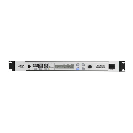
This manual describes the VC-300HD and the VC-200HD. When reading this manual, please note the following.
• VC-300HD-specific features are marked with
• The illustrations used for this manual's explanations depict the VC-300HD. Some of the panel inscriptions and
connectors on the VC-200HD are different.
201b
Before using this unit, carefully read the sections entitled: "IMPORTANT SAFETY INSTRUCTIONS" (p. 2), "USING
THE UNIT SAFELY" (p. 4–5), and "IMPORTANT NOTES" (p. 6). These sections provide important information
concerning the proper operation of the unit. Additionally, in order to feel assured that you have gained a good grasp
of every feature provided by your new unit, Owner's Manual should be read in its entirety. The manual should be
saved and kept on hand as a convenient reference.
202
Copyright © 2007 ROLAND CORPORATION
All rights reserved. No part of this publication may be reproduced in any form without the written permission of ROLAND
CORPORATION.
in the title.
Advertisement
Table of Contents

Related Manuals for Roland VC-200HD


Summary of Contents for Roland VC-200HD
- Page 1 Owner’s Manual should be read in its entirety. The manual should be saved and kept on hand as a convenient reference. Copyright © 2007 ROLAND CORPORATION All rights reserved. No part of this publication may be reproduced in any form without the written permission of ROLAND CORPORATION. in the title.
-
Page 2: Important Safety Instructions
The wire which is coloured BROWN must be connected to the terminal which is marked with the letter L or coloured RED. DECLARATION OF CONFORMITY Compliance Information Statement Model Name : VC-300HD / VC-200HD Type of Equipment : Multi-Format Converter Responsible Party : Roland Systems Group U.S. -
Page 3: Table Of Contents
Daily Maintenance ...43 Fan...43 Troubleshooting ... 44 Video...44 Audio...44 Miscellaneous ...45 Main Specifications... 46 Exterior Dimensions Diagram ...47 VC-200HD Block Diagram ...48 VC-300HD Block Diagram ...49 Output Format Support Chart...50 Connecting with Nonlinear PC Software ...51 Memo... 52 Index... 54... -
Page 4: Using The Unit Safely
• Do not attempt to repair the unit, or replace parts within it (except when this manual provides specific instructions directing you to do so). Refer all servicing to your retailer, the nearest Roland Service Center, or an authorized Roland distributor, as listed on the “Information” page. - Page 5 012a • Immediately turn the power off, remove the power cord from the outlet, and request servicing by your retailer, the nearest Roland Service Center, or an authorized Roland distributor, as listed on the “Information” page when: • The power-supply cord, or the plug has been damaged;...
-
Page 6: Important Notes
IMPORTANT NOTES 291b In addition to the items listed under “IMPORTANT SAFETY INSTRUCTIONS” and “USING THE UNIT SAFELY” on pages 2 and 4–5, please read and observe the following: Power Supply • Do not connect this unit to same electrical outlet that is being used by an electrical appliance that is controlled by an inverter (such as a refrigerator, washing machine, microwave oven, or air conditioner), or that contains a... -
Page 7: Features
1080i. High-quality 4:4:4 10-bit Processing The VC-200HD/VC-300HD use 4:4:4/10-bit processing for video calculations. Analog component input is also digitized at 4:4:4 with 10-bit depth. This means that video handled by the unit is processed at the highest quality possible, so there is no degradation. -
Page 8: Checking The Included Items
Checking the Included Items The VC-300HD/VC-200HD is packaged with the following items. Please check that all of the items are included. * If you find that any item is missing, contact the nearest authorized EDIROL/Roland distributor in your country. VC-300HD / VC-200HD Power Cord * Use only the attached power-supply cord. -
Page 9: Basic Operation
Basic Operation... -
Page 10: Panel Descriptions
Panel Descriptions Front Panel i.LINK Connector (Front Panel) This connector handles the input/output of HDV/DV signals and allows for connection of HDV/DV video equipment. * Please do not use this together with the i.LINK connector (p. 13) on the rear panel of the unit. If they are used together, the connected video equipment may not operate properly. -
Page 11: Side Panel
Display Shows the Status screens (four types) indicating the status of the unit. Pressing the PAGE button cycles you through the Status screens. The Menu screen is displayed by pressing MENU button. While the Menu screen is displayed, the MENU button is lit. PAGE Button Pressed to select what is shown in the display, such as the Status screen or Menu screen. -
Page 12: Rear Panel
Panel Descriptions Rear Panel AC Inlet Accepts connection of the supplied power cord. AUDIO OUTPUT Connectors CH1 and CH2 Connectors (XLR Type/Balanced Type) CH3 and CH4 Connectors (RCA Phono Type, Unbalanced Input) These connectors provide output of analog audio. Here is where you connect equipment such as monitoring speakers or a television, or a video deck if you intend to record the output. - Page 13 TERMINATOR Switch Switch this on when you don’t want to loop-through the synchronizing signal from the REF OUTPUT connector. REF OUTPUT Connector This is the loop through output connector for external synchronizing signals input via the REF INPUT connector. It is connected to the external synchronizing signal input connector of the video equipment to which the unit is synchronized.
-
Page 14: Connecting
* The input/output combinations are described on the pages indicated in the chart with p. ??. * Wherever “VC-300HD” appears, it means that it is supported only on the VC-300HD. * Wherever “—” is shown, it means that it is not supported on either the VC-200HD or VC-300HD. COMPONENT... - Page 15 About the Procedures In general, the operating procedures introduced in p. 16–25 involve proceeding through the steps below. Connect the devices Select the input connectors (video/audio) See “Selecting the video input connector” (p. 28), “Selecting the audio input connector” (p. 29). Select the output format (video only) Output of the audio/video in the selected format begins from the appropriate output connectors.
-
Page 16: Converting Hd Component To Hdv
5-2. Use the VALUE/ENTER knob to select "COMPONENT." 5-3. Press the VALUE/ENTER knob to confirm the selection. COMPONENT INPUT iLink IEEE1394 VC-200HD / VC-300HD HDV device When the output from the i.LINK connector on this unit is not recognized by the HDV device, turn off power to this unit and then restart it. - Page 17 Converting HD Component or SD Component to DV By using the scaling feature of the VC-300HD/VC-200HD, HD component video can be down- converted to SD size as well as converted to DV. Perform the settings on the previous page, and connect the DV device to the i.LINK connector.
-
Page 18: Converting Hd-Sdi To Hdv
Connecting Converting HD-SDI to HDV Since the VC-300HD/VC-200HD offers HD-SDI input, the HD-SDI or SDI from an HD video device can be converted to HDV. The output from the HD video switcher can be recorded in HDV, or the video from an HD video deck can be converted to HDV. - Page 19 Converting SD-SDI to HDV By using the scaling feature of the VC-300HD/VC-200HD, SD-SDI component video can be up-converted to HD size as well as converted to HDV. In this case, conversion can be performed using the same procedure as shown on the previous page.
-
Page 20: Converting Computer Screens (Dvi Or Vga) To Hdv
Because the computer screen can be recorded in HD, small text and graphics do maintain clarity. * To input VGA output to the VC-300HD/VC-200HD, please use an RGB-DVI conversion connector and cable to convert to the DVI connector. - Page 21 The DVI-I INPUT connector DDC settings can be changed with the following procedure. * The input format selection cannot be fixed. "AUTO" is shown for all displays. 1. Connect the DVI-I INPUT connector on the VC-300HD (VC-200HD) to the DVI-I OUTPUT connector.
- Page 22 * When converting to PAL, select "576/50i" in step 6. For NTSC, select “480i/60.” Converting DVI-I The DVI-I output with the VC-300HD/VC-200HD is converted to the video format selected with Step 6. The output video format is as shown below.
-
Page 23: Converting Hdv To Hd Component
Converting HDV to HD Component When video recorded in HDV is converted to HD component, it can be used as HD analog video on an HD video device or in an HD linear editing environment. HDV device Connection and Configuration Connect the HDV device to the i.LINK connector using a i.LINK (IEEE1394) cable. - Page 24 Converting HDV to SD Component By using the scaling feature of the VC-300HD/VC-200HD, HDV can be down-converted to SD size as well as converted to SD component. In this case, after connecting using the procedure on the previous page, select “SD” in Step 5.
-
Page 25: Converting Hdv To Hd-Sdi
Converting HDV to HD-SDI Video recorded in HDV can be converted to HD-SDI and copied to an HD video device, such as HDCAM or DVCPRO HD, or transmitted over a long distance. HDV device Connection and Configuration Connect the HDV device to the i.LINK connector using a i.LINK (IEEE1394) cable. Connect the HD video device to the COMPONENT OUTPUT connector using a BNC cable. - Page 26 "450: SDI OUT Audio Ch" (p. 41) from the Menu (p. 32). Converting DV to HD-SDI By using the scaling feature of the VC-300HD/VC-200HD, DV can be up-converted to HD size as well as converted to HD-SDI. In this case, after connecting using the procedure on the previous page, select a video format in Step 5 that is supported by the HD video device being used.
-
Page 27: Installation
* When turning the unit over, be careful not to drop or allow the unit to fall over. Cautions when Rack Mounting ● When mounting the VC-300HD/VC-200HD in a rack, please pay attention to the following to assure effective cooling. -
Page 28: Basic Operations
Basic Operations Turning Power On/Off Turning power on ● Once the connections have been completed (p. 14), turn on power to your various devices in the order specified. By turning on devices in the wrong order, you risk causing malfunction and/or damage to speakers and other devices. -
Page 29: Selecting The Audio Input Connector
Selecting the audio input connector This unit has several sound input connectors: AUDIO INPUT connectors, i.LINK connector, and HD-SDI connector (VC-300HD only). At the factory settings, the audio input connector appropriate for the video selected under "Selecting the video input connector" (p. 28) is selected. -
Page 30: Test Pattern / Test Tone Output
Basic Operations Test Pattern / Test Tone Output The VC-300HD/VC-200HD can easily output test patterns or test tones. Press the OUTPUT button until "390: Test Pattern" or "391: Test Tone" is shown in the display Press the PAGE button once to display the test pattern. Press the PAGE button twice to display the test tone. -
Page 31: Showing The Display
Showing the Display The display shows the status of the device. It also shows the menu screens for the various settings. Display * The display may be difficult to read depending on the angle from which the unit is viewed. The character contrast on the display and brightness of the backlight are adjusted with the "900: LCD Contrast"... -
Page 32: Menu Display And Operation
The Menu screen is shown on the display when the MENU button is pressed. Various settings for the VC-300HD/ VC-200HD are performed on the Menu screen. * See “Menus and settings” (p. 36) for items displayed on the Menu screen. -
Page 33: Adjusting The Display
Changing the Value of a Setting Press the VALUE/ENTER knob and the setting’s value blinks, indicating that it can be changed. Use the VALUE/ENTER knob to change the value of the setting. The selected value for the setting is confirmed by pressing the VALUE/ ENTER knob. - Page 34 Basic Operations...
-
Page 35: Appendices
Appendices... -
Page 36: Menus And Settings
Menus and settings * See Menu Display and Operation (p. 32) for menu operations. 100–162 Input Parameter Item Item Name Number Video Source i.LINK IN COMPONENT IN In 480i Setup DVI-D IN DVI-A IN DVI-A AutoConfig DVI-A H Position DVI-A V Position DVI-A Frequency DVI-A Phase SDI IN... - Page 37 100–162 Input Parameter (continued) Item Item Name Description and Available Settings Number In Ch1&2 NomLv Sets the input Nominal level for AUDIO INPUT connector CH1 and CH2. +4dBu, -2dBu, -4dBu, -10dBu: Larger numerical values indicate higher levels. In Ch3&4 NomLv Sets the input Nominal level for AUDIO INPUT connector CH3 and CH4.
- Page 38 Selects the timecode to embed in the HDV, DV, or HD-SDI output. * On the VC-200HD, this is set to "Off" at the factory. [Off]: Time code is not embedded. Free Run: Timecode is generated internally. The timecode is generated from when the power is turned on or when “271: TC Offset”...
- Page 39 200–275 Processing Parameter (continued) Item Item Name Description and Available Settings Number User Bit Sets the user bit embedded in the timecode when "Free Run" is set with "270: TC Generate." * Because there is no impact when the value set for "270: TC Generate" is not "Free Run," the input user bit is passed through without any change.
- Page 40 Menus and settings 300–391 Output Parameter (continued) Item Item Name Number Test Pattern Test Tone Note: The values enclosed in a [box] are the factory defaults. Description and Available Settings Displays the test pattern. [Off]: No test pattern is displayed. 75%: Displays a 75% color bar.
- Page 41 400–452 SDI Parameter Item Item Name Description and Available Settings Number SDI IN AudioCh Selects the channels to be used for conversion with "AUDIO PROCESSOR [CH A&B] " or "AUDIO PRO- CESSOR [CH C&D] " (p. 48) from the embedded audio input via the HD-SDI IN connector. AB:1/2 CD:1/2: Channels 1 and 2 are used for [CH A&B], and channels 1 and 2 are used for [CH C&D].
-
Page 42: Input / Output Signal
Input / Output Signal HDV (High Definition Video) is the standard term used for the format to record High-definition television (HDTV) onto DV tape used in digital video cameras. HDV uses MPEG-2 for video compression. DV uses a method that compresses each video frame individually, but HDV realizes high definition recording with the same data volume as DV by using MPEG- 2 inter-frame prediction. -
Page 43: Installation And Maintenance
Installation and Maintenance Installing and Removing the Rack Mount Fittings The rack mounts fittings for this device can be installed or removed. Cautions regarding removing the rack mount fittings • Please use a Phillips screwdriver that fits the screw head (No. 2 screwdriver). -
Page 44: Troubleshooting
● Does the connecting cable contain a resistor? ➔ Use a connecting cable that doesn’t contain a resistor (such as one from the Roland PCS series). The video lags behind the audio ● Does the video input to this device pass through a video mixer? ➔... -
Page 45: Miscellaneous
If a signal with embedded time code, such as an SDI signal, is set in the input when using VC-300HD, set to "Thru" or "Offset." When using the VC-200HD or when setting a signal that does not have embedded time code, such as a composite signal or a DVI-I signal, with the VC-300HD, set to "Free Run."... -
Page 46: Main Specifications
Main Specifications VC-200HD / VC-300HD: MULTI-FORMAT CONVERTER Video Input Format ❥ IEEE1394 (i.LINK) HDV: 1080/59.94i, 1080/50i, 720/59.94p, 720/50p 480/59.94, 576/50 ❥ Component Y/Pb/Pr: 1080/59.94i, 1080/50i, 720/59.94p, 720/50p, 480/59.94p, 576/50p, 480/59.94i, 576/50i ❥ DVI-I Digital (RGB): 1600x1200/60Hz, 1400x1050/60/75Hz, 1280x1024/60/75Hz, 1280x768/60Hz, 1280x960/60Hz, 1152x864/75Hz,... -
Page 47: Exterior Dimensions Diagram
Video Connectors IEEE1394 Connector(i.LINK) 6-pin Type, conforms to IEEE1394, HDV standards, Same connector on front and rear ❥ COMPONENT Input Connector HD/SD Y/Pb/Pr BNC Type 75 ohms, BiLevel, TriLevel Sync ❥ DVI-I Input Connector DVI 29pin single link RGB (8 bit each) Digital RGB dot clock: 25-161MHz (VGA to UXGA) Analog RGB: R/G/B 0.7 Vp-p, 75 ohms, H/V 5VTTL, RGB dot clock: 25-90MHz(VGA to XGA) -
Page 48: Vc-200Hd Block Diagram
Main Specifications VC-200HD Block Diagram DIGITAL ANALOG MODULE DIGITAL ANALOG HDV DV i.LINK IN FRONT REAR ENCODE DECODE VIDEO PROCESSOR UP DOWN CONVERSION FORMAT CONVERSION FRAME SYNCRONIZER COLOR LEVEL ADJUST NOISE REDUCTION AUDIO PROCESSOR DELAY 3BAND EQUALIZER GAIN ADJUST SAMPLING RATE CONVERT HDV DV i.LINK IN... -
Page 49: Vc-300Hd Block Diagram
VC-300HD Block Diagram HDV DV AUDIO IN i.LINK IN DELAY DELAY 3BAND EQ 3BAND EQ AUDIO AUDIO IN i.LINK AUDIO DV / Main Specifications HDV DV HD - SDI i.LINK IN SDI IN ( Embedded Audio ) DELAY DELAY 3BAND EQ 3BAND EQ Audio Embedded... -
Page 50: Output Format Support Chart
Main Specifications Output Format Support Chart The following lists the video formats that can be output with the output connectors mounted on this device. Format/Output i.LINK Connector Connector — 1080/59.94p — 1080/50p 1080/59.94i 1080/50i 720/59.94p 720/29.97p 720/50p 720/25p 480/59.94p 576/50p 480/59.94i (NTSC) 576/50i (PAL) indicates that the combination can be output. -
Page 51: Connecting With Nonlinear Pc Software
*2 When capturing DV, select either "480/59.94i" (for NTSC DV) or "576/50i" (for PAL DV) with the VC-300HD/VC200HD "110:i.LINK IN" menu to put the VC-300HD/VC-200HD in a state whereby it is ready to accept DV signals. This list does not guarantee any operations. -
Page 52: Memo
Memo... - Page 53 Memo...
-
Page 54: Index
Index Numerics ... 29, 37 32 kHz ... 37 48 kHz ... 12 AC Inlet ... 30, 32 Audio Delay ... 12 AUDIO INPUT Connector ... 31 Audio Level ... 12 AUDIO OUTPUT Connector ... 12 balanced (XLR) type jack ... - Page 55 This product complies with the requirements of EMCD 2004/108/EC and LVD 2006/95/EC. FEDERAL COMMUNICATIONS COMMISSION RADIO FREQUENCY INTERFERENCE STATEMENT This equipment has been tested and found to comply with the limits for a Class B digital device, pursuant to Part 15 of the FCC Rules.
- Page 56 Information When you need repair service, call your nearest EDIROL/Roland Service Center or authorized EDIROL/Roland distributor in your country as shown below. CENTRAL/LATIN ASIA AMERICA INDONESIA BRAZIL PT. Citra IntiRama Roland Brasil Ltda. JL. Cideng Timur No. 15J-15O Rua San Jose, 780 Sala B...