Table of Contents
Advertisement
www.nordictrack.com
Model No. NTL17215.1
Serial No.
Write the serial number in the space
above for reference.
Serial Number
Decal
ACTIVATE YOUR
WARRANTY
To register your product and
activate your warranty today, go
to www.nordictrackservice.com/
registration.
CUSTOMER CARE
For service at any time, go to
www.nordictrackservice.com.
Or call 1-800-TO-BE-FIT
(1-800-862-3348)
Mon.–Fri. 6 a.m.–6 p.m. MT
Sat. 8 a.m.–12 p.m. MT
Please do not contact the store.
CAUTION
Read all precautions and instruc-
tions in this manual before using
this equipment. Save this manual
for future reference.
USER'S MANUAL
Advertisement
Table of Contents

Related Manuals for NordicTrack NTL17215.1


Summary of Contents for NordicTrack NTL17215.1
- Page 1 Model No. NTL17215.1 USER’S MANUAL Serial No. Write the serial number in the space above for reference. Serial Number Decal ACTIVATE YOUR WARRANTY To register your product and activate your warranty today, go to www.nordictrackservice.com/ registration. CUSTOMER CARE For service at any time, go to www.nordictrackservice.com.
-
Page 2: Table Of Contents
Note: The decals may not be shown at actual size. The BLUETOOTH ® word mark and logos are registered trademarks of Bluetooth SIG, Inc. and are used under license. Google Maps is a trademark of Google Inc. NORDICTRACK is a registered trademark of ICON Health & Fitness, Inc. -
Page 3: Important Precautions
5. The treadmill is intended for home use only. purchase a surge suppressor, see your local Do not use the treadmill in any commercial, NORDICTRACK dealer, call the telephone rental, or institutional setting. number on the front cover of this manual, or see your local electronics store. - Page 4 19. Always stand on the foot rails when starting 26. When folding or moving the treadmill, make or stopping the walking belt. Always hold the sure that the storage latch is holding the handrails while using the treadmill. frame securely in the storage position. 20.
- Page 6 STANDARD SERVICE PLANS...
-
Page 7: Before You Begin
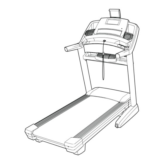
BEFORE YOU BEGIN Thank you for selecting the revolutionary reading this manual, please see the front cover of this NORDICTRACK COMMERCIAL 2450 treadmill. manual. To help us assist you, please note the product ® The COMMERCIAL 2450 treadmill offers an impres- model number and serial number before contacting us. -
Page 8: Part Identification Chart
PART IDENTIFICATION CHART Use the drawings below to identify small parts used for assembly. The number in parentheses below each draw- ing is the key number of the part, from the PART LIST near the end of this manual. The number following the key number is the quantity used for assembly. -
Page 9: Assembly
ASSEMBLY • Assembly requires two persons. • To identify small parts, see page 8. • Place all parts in a cleared area and remove the • Assembly requires the following tools: packing materials. Do not dispose of the packing materials until you fi nish all assembly steps. the included hex key •... - Page 10 3. Identify the Left and Right Upright Covers (89, 90). Film Slide the Left Upright Cover (89) onto the left Upright (84), and slide the Right Upright Cover (90) onto the right Upright. Next, press the Upright Covers downward until they snap into place.
- Page 11 6. Hold the Tray (79) near the right Upright (84). Wrap the tie in the hole in the side of the Upright around the end of the fan wire (B). Pull the fan wire through the hole and out of the top of the Upright.
- Page 12 9. IMPORTANT: To avoid damaging the Pulse Crossbar (80), do not use power tools, and do not overtighten the #10 x 3/4" Screws (6) or the 5/16" x 2" Screws (2). Orient the Pulse Crossbar (80) as shown. Attach the Pulse Crossbar with two of the 5/16" x 2" Screws (2) that you removed in step 3, two 5/16"...
- Page 13 11. Attach the console assembly (D) to the Handrails (74) with four 5/16" x 2" Screws (2) and four 5/16" Star Washers (8); start all four Screws, and then tighten them. Be careful not to pinch the wires and cables. Then, insert the wires and cables upward into the console assembly (D).
- Page 14 13. Set the Left Handrail Top Cover (73) on the left Handrail (74). Start four #8 x 3/4" Truss Head Screws (24) into the Left Handrail Bottom Cover (75), the left Handrail, and the Left Handrail Top Cover. Slide the Left Handrail Top and Bottom Covers forward against the console assembly (D) as shown;...
- Page 15 15. Remove the 5/16" Nut (9) and the 5/16" x 2 1/4" Bolt (4) from the bracket on the Frame (52). Align the upper end of the Storage Latch (56) with the bracket on the Frame (52), and insert the 5/16" x 2 1/4" Bolt (4) through the bracket and the Storage Latch.
-
Page 16: The Chest Heart Rate Monitor
THE CHEST HEART RATE MONITOR HOW TO PUT ON THE HEART RATE MONITOR • Store the heart rate monitor in a warm, dry place. Do not store the heart rate monitor in a plastic bag or If the heart rate monitor looks like the one shown other container that may trap moisture. -
Page 17: How To Use The Treadmill
HOW TO USE THE TREADMILL HOW TO CONNECT THE POWER CORD nominal 120-volt circuit capable of carrying 15 or more amps. To avoid overloading the circuit, do Use a Surge Suppressor not plug other electrical devices, except for low- power devices such as cell phone chargers, into Your treadmill, like other electronic equipment, can be the surge suppressor or into an outlet on the same damaged by sudden voltage changes in your home’s... -
Page 18: How To Upgrade The Console
HOW TO UPGRADE THE CONSOLE The treadmill console has been preconfi gured to operate with a digital TV (see the drawings below). To learn about the features of the console, see page 19. To learn about the features of the digital TV, see the user’s manual included with the digital TV. - Page 19 CONSOLE DIAGRAM MAKE YOUR FITNESS GOALS A REALITY WITH FEATURES OF THE CONSOLE IFIT.COM The advanced treadmill console offers an array of fea- With your new iFit-compatible fitness equipment, you tures designed to make your workouts more effective can use an array of features on iFit.com to make your and enjoyable.
- Page 20 HOW TO TURN ON THE POWER Note: The console can display speed and distance in either miles or kilometers. To find which unit of mea- IMPORTANT: If the treadmill has been exposed to surement is selected, see step 4 on page 27. For cold temperatures, allow it to warm to room tem- simplicity, all instructions in this section refer to miles.
- Page 21 HOW TO SET UP THE CONSOLE To use the equipment settings mode, see page 27. To use the sound system, see page 28. To Before using the treadmill for the first time, set up the use the Internet browser, see page 29. To use the console.
- Page 22 The walking belt will begin to move at 1 mph. As As you walk or run on the treadmill, the screen can you exercise, change the speed of the walking belt show the following workout information: as desired by pressing the Speed increase and decrease buttons.
- Page 23 To measure your heart rate, stand on the foot HOW TO USE AN ONBOARD WORKOUT rails and hold the contacts with your palms for approximately ten seconds; avoid moving your 1. Insert the key into the console. hands. When your pulse is detected, your heart rate will be shown.
- Page 24 The workout will continue in this way until the last 7. When you are finished exercising, remove the segment ends. The walking belt will then slow to key from the console. a stop and a workout summary will appear on the screen.
- Page 25 The workout will continue until you reach the goal HOW TO USE AN IFIT WORKOUT that you set. The walking belt will then slow to a stop, and a workout summary will appear on the Note: To use an iFit workout, you must have access screen.
- Page 26 To compete in a race that you have previously 6. Monitor your progress with the displays. scheduled, touch the Compete button. To view your Workout History, touch the Track button. To use a See step 5 on page 22. The screen may also set-a-goal workout, touch the Set A Goal button show a map of the trail you are walking or running.
- Page 27 HOW TO USE THE EQUIPMENT SETTINGS MODE 6. Select an update time. 1. Select the settings main menu. To select a time for automatic firmware updates, touch the Update Time button and select the Insert the key into the console desired time.
- Page 28 9. Enable or disable the street view. To set the amount of time the console will wait before it automatically resets, touch the Safety During some workouts, the screen may show a Screen Timeout button to view a list of times. Then, map.
- Page 29 HOW TO USE THE INTERNET BROWSER 3. Update the console firmware. Note: To use the browser, you must have access to a For the best results, regularly check for firm- wireless network including an 802.11b/g/n router with ware updates. SSID broadcast enabled (hidden networks are not supported).
- Page 30 IMPORTANT: Keep pets, feet, and other objects 3. Enable Wi-Fi. away from the treadmill while the incline sys- tem is calibrating. In an emergency, pull the key Make sure that the Wi-Fi checkbox is marked with from the console to stop the incline calibration. a green checkmark.
- Page 31 To disconnect from a wireless network, select the HOW TO ADJUST THE CUSHIONING SYSTEM wireless network and then touch the Forget button. The treadmill features a cushioning system that If you are having problems connecting to an reduces the impact as you walk or run on the treadmill. encrypted network, make sure that your password is correct.
-
Page 32: How To Fold And Move The Treadmill
HOW TO FOLD AND MOVE THE TREADMILL HOW TO FOLD THE TREADMILL HOW TO MOVE THE TREADMILL To avoid damaging the treadmill, adjust the incline Before moving the treadmill, fold it as described at the to zero before you fold the treadmill. Then, remove left. -
Page 33: Maintenance And Troubleshooting
MAINTENANCE AND TROUBLESHOOTING MAINTENANCE c. Check the power switch located on the treadmill frame near the power cord. If the switch protrudes Regular maintenance is important for optimal perfor- as shown, the switch has tripped. To reset the mance and to reduce wear. Inspect and properly tighten power switch, wait for fi... - Page 34 SYMPTOM: The incline of the treadmill does not c. Your treadmill features a walking belt coated with change correctly high-performance lubricant. IMPORTANT: Never apply silicone spray or other substances to a. Calibrate the incline system (see step 4 on the walking belt or the walking platform unless instructed to do so by an authorized service page 29).
- Page 35 b. If the walking belt slips when walked on, fi rst SYMPTOM: The tablet holder does not stay in place remove the key and UNPLUG THE POWER CORD. Using the hex key, turn both idler roller a. Rotate the tablet holder backwards. Then, tighten screws clockwise, 1/4 of a turn.
-
Page 36: Exercise Guidelines
EXERCISE GUIDELINES Burning Fat—To burn fat effectively, you must exer- WARNING: cise at a low intensity level for a sustained period of Before beginning this time. During the first few minutes of exercise, your or any exercise program, consult your physi- body uses carbohydrate calories for energy. - Page 37 SUGGESTED STRETCHES The correct form for several basic stretches is shown at the right. Move slowly as you stretch —never bounce. 1. Toe Touch Stretch Stand with your knees bent slightly and slowly bend forward from your hips. Allow your back and shoulders to relax as you reach down toward your toes as far as possible.
-
Page 38: Part List
PART LIST Model No. NTL17215.1 R0915A Key No. Qty. Description Key No. Qty. Description 5/16" x 3/4" Screw Drive Roller/Pulley 5/16" x 2" Screw Frame 5/16" x 1 3/4" Bolt 5/16" x 2 1/4" Bolt Drive Motor #8 x 3/4" Screw Motor Belt #10 x 3/4"... - Page 39 Key No. Qty. Description Key No. Qty. Description Right Tray Cushion Rod Bracket 1/2" Thrust Washer Cushion Rod Controller Clamp Cushion Wheel Key/Clip Cushion Plate Console Frame Cap Cushion Spring Console Frame Left Rear Cap Wire Tie Right Rear Cap #8 x 5/8"...
-
Page 40: Exploded Drawing
EXPLODED DRAWING A Model No. NTL17215.1 R0915A... - Page 41 EXPLODED DRAWING B Model No. NTL17215.1 R0915A 33 112 33 117 115 111...
- Page 42 EXPLODED DRAWING C Model No. NTL17215.1 R0915A...
- Page 43 EXPLODED DRAWING D Model No. NTL17215.1 R0915A...
-
Page 44: Ordering Replacement Parts
ORDERING REPLACEMENT PARTS To order replacement parts, please see the front cover of this manual. To help us assist you, be prepared to provide the following information when contacting us: • the model number and serial number of the product (see the front cover of this manual) •...