Table of Contents
Advertisement
Quick Links
Model No. NTL19124-INT.2
Serial No.
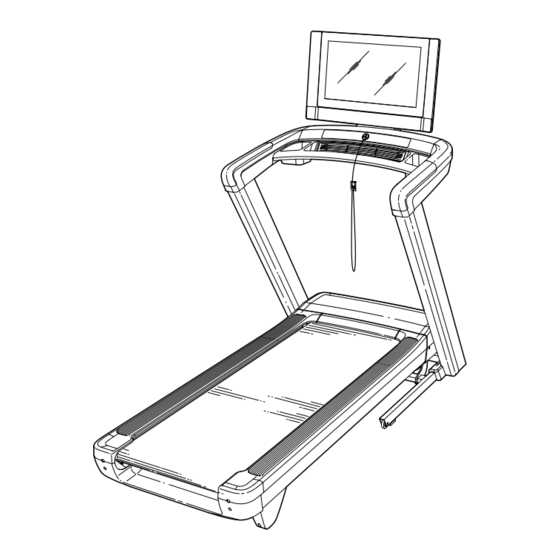
Write the serial number in the space
above for reference.
Serial Number
Decal
MEMBER CARE
UNITED KINGDOM
Website: iFITsupport.eu
E-mail: csuk@iconeurope.com
Write:
iFIT Health & Fitness Limited
Unit 4, Westgate Court
Silkwood Park
OSSETT
WF5 9TT
UNITED KINGDOM
AUSTRALIA
Call: 1800 993 770
E-mail: australiacc@iFIT.com
Write:
iFIT Inc.
PO Box 635
WINSTON HILLS NSW 2153
AUSTRALIA
CAUTION
Read all precautions and
instructions in this manual before
using this equipment. Keep this
manual for future reference.
USER'S MANUAL
iconeurope.com
Advertisement
Table of Contents

Related Manuals for NordicTrack NTL19124-INT.2


Summary of Contents for NordicTrack NTL19124-INT.2
- Page 1 Model No. NTL19124-INT.2 USER’S MANUAL Serial No. Write the serial number in the space above for reference. Serial Number Decal MEMBER CARE UNITED KINGDOM Website: iFITsupport.eu E-mail: csuk@iconeurope.com Write: iFIT Health & Fitness Limited Unit 4, Westgate Court Silkwood Park...
-
Page 2: Table Of Contents
RECYCLING INFORMATION ............Back Cover NORDICTRACK and IFIT are registered trademarks of iFIT Inc. The Bluetooth word mark and logos are regis- ®... -
Page 3: Important Precautions
IMPORTANT PRECAUTIONS WARNING: To reduce the risk of burns, fire, electric shock, or injury to persons, read all important precautions and instructions in this manual and all warnings on your treadmill before using your treadmill. iFIT assumes no responsibility for personal injury or property damage sus- tained by or through the use of this product. - Page 4 20. When a person is walking on the treadmill, 26. Do not change the incline of the treadmill by the noise level of the treadmill will increase. placing objects under the treadmill. 21. Keep fingers, hair, and clothing away from 27.
-
Page 5: Warning Decal Placement
WARNING DECAL PLACEMENT This drawing shows the locations of the warning decals. If a decal is missing or illegible, see the front cover of this manual and request a free replacement decal. Apply the decal in the location shown. Note: The decals may not be shown at actual size. -
Page 6: Before You Begin
BEFORE YOU BEGIN Thank you for selecting the new NORDICTRACK reading this manual, please see the front cover of this ® COMMERCIAL 2450 treadmill. The COMMERCIAL manual. To help us assist you, note the product model 2450 treadmill provides an impressive selection of fea- number and serial number before contacting us. -
Page 7: Part Identification Chart
PART IDENTIFICATION CHART Use the drawings below to identify small parts used for assembly. The number in parentheses below each draw- ing is the key number of the part, from the PART LIST near the end of this manual. The number following the key number is the quantity used for assembly. -
Page 8: Assembly
ASSEMBLY • Assembly requires two persons. • Left parts are marked “L” or “Left” and right parts are marked “R” or “Right.” • Place all parts in a cleared area and remove the packing materials. Do not dispose of the packing •... - Page 9 2. IMPORTANT: You will connect wires in one or more of the following steps. For your tread- mill to function properly, connect the wires as described below. Note: The actual wires may look different from the wires shown. First, firmly push the wires (V) into each connec- tor (W, X) to make sure that the wires are fully seated.
- Page 10 4. Do not to pinch the Belly Pan Wire (80) during this step. Have a second person hold the Right Upright (94) against the Upright Base (101). Insert two 3/8" x 1 1/4" Screws (1) with two 3/8" Star Washers (8) into the top of the bracket on the Right Upright (94), and partially tighten the Screws into the Upright Base (101);...
- Page 11 6. Connect the Handrail Wire (91) to the Upright Wire (92). For your treadmill to function properly, make sure to connect the wires as described in step 2. Then, insert the wires into the Right Upright (94). 7. Identify the Right Handrail Cover (84). Insert the front edge of the Right Handrail Cover into the top of the handrail assembly (E) on the right side of the treadmill as shown.
- Page 12 8. Do not pinch the wires (G) during this step. Have a second person hold the console assembly (F) near the handrail assembly (E). Make sure that the console assembly is properly oriented so that the curved edge (H) of the Console Pivot Bracket (117) faces the front (I) of the handrail assembly.
- Page 13 10. Rotate the console assembly (F) back to its original position. Firmly tighten the two M6 x 25mm Screws (6) that you attached in step 8. Next, identify the Right Pivot Cover (116). Attach the Right Pivot Cover to the Console Pivot Bracket (117) with an M4 x 20mm Screw (4);...
- Page 14 12. Raise the Frame (66) to the position shown. IMPORTANT: Have a second person hold the Frame until step 14 is completed. Remove the two 5/16" x 3/4" Screws (9) from the Latch Crossbar (62). Note: The Latch Crossbar is not preattached to the treadmill. Next, orient the Latch Crossbar (62) as shown.
- Page 15 14. Remove the 5/16" Nut (12) and the 5/16" x 2 1/4" Bolt (11) from the bracket on the Latch Crossbar (62). 12 O Next, align the upper end of the Storage Latch (65) with the bracket on the Latch Crossbar (62), and insert the 5/16"...
- Page 16 16. Identify the Right Base Cover (98). Slide the Right Base Cover under the Belly Pan Wire (80) and onto the Upright Base (101). Make sure that the Right Base Cover is under the Belly Pan Wire. Repeat this step on the left side of the tread- mill with the Left Base Cover (not shown).
-
Page 17: How To Plug In The Power Cord
Dubai HOW TO PLUG IN THE POWER CORD This product must be earthed. If it should malfunc- Follow the steps below to plug in the power cord. tion or break down, earthing provides a path of least resistance for electric current to reduce the risk of 1. -
Page 18: How To Use The Treadmill
HOW TO USE THE TREADMILL The console also features wireless technology that FEATURES OF THE CONSOLE enables the console to connect to iFIT . With iFIT, you ® The advanced console offers a selection of features can choose from a rotating selection of featured work- designed to make your workouts more effective and outs that automatically control the speed and incline of enjoyable. - Page 19 HOW TO TURN ON THE CONSOLE HOW TO TURN OFF THE CONSOLE When you are finished using the treadmill, first remove IMPORTANT: If the treadmill has been exposed to the key from the console and put it in a secure place. cold temperatures, allow it to warm to room tem- perature before you turn on the console.
- Page 20 in this manual. Also, some settings and features HOW TO SET UP THE CONSOLE described in this manual may no longer be Before you use the treadmill for the first time, set up enabled. Take time to explore the console to learn the console.
- Page 21 includes a decimal—such as 3.5 mph—press two HOW TO USE THE MANUAL MODE numbered buttons in succession. For example, to select a speed setting of 3.5 mph, press the 3 but- 1. Insert the key into the console. ton and then immediately press the 5 button. Note: See HOW TO TURN ON THE CONSOLE on This feature will not function when the console is page 19.
- Page 22 6. Follow your progress. HOW TO USE A FEATURED WORKOUT The console offers several display modes. The To use a featured workout, the console must be display mode that you select will determine which connected to a wireless network (see HOW TO workout information is shown.
- Page 23 To enable the smart adjust feature, touch the 4. Get ready for the workout. screen in any open space and then touch the smart Touch Start Workout; the walking belt will start to adjust toggle. move at a low speed and a warm-up period will begin.
- Page 24 If you make a mistake, touch Undo in the map HOW TO CREATE A DRAW-YOUR-OWN-MAP options. WORKOUT To use a draw-your-own-map workout, you must be The screen will display the elevation and distance logged into your iFIT account (see step 3 on page 25) statistics for the workout.
- Page 25 The featured iFIT workouts shown on the home HOW TO USE AN IFIT WORKOUT screen will change periodically. To use an iFIT workout, you must be logged into your iFIT account (see step 3 below) and the console must The workout library contains all of the iFIT work- be connected to a wireless network (see HOW TO outs available for the treadmill, organized into CONNECT TO A WIRELESS NETWORK on page 28).
- Page 26 7. Get ready for the workout. HOW TO CHANGE CONSOLE SETTINGS Touch Start Workout; the walking belt will start to IMPORTANT: Firmware updates (see step 6) move at a low speed and a warm-up period will are always designed to improve your exercise begin.
- Page 27 The screen will show the progress of the update. 3. Customize workout settings. When the update is complete, the console will turn To customize workout settings and enable work- off and then turn back on. If it does not, press the out features, touch In Workout and then touch the power switch into the off position.
- Page 28 Note: You must have your own wireless network HOW TO CONNECT TO A WIRELESS NETWORK and an 802.11b/g/n router with SSID broadcast To use iFIT workouts and to use several other features enabled (hidden networks are not supported). of the console, the console must be connected to a wireless network.
- Page 29 HOW TO USE THE FAN HOW TO USE AN OPTIONAL HEART RATE MONITOR The fan has several speed settings, including an auto mode. While the Whether your auto mode is selected, the speed of goal is to the fan will automatically increase or burn fat or to decrease as the speed of the walking strengthen your...
-
Page 30: How To Fold And Move The Treadmill
HOW TO FOLD AND MOVE THE TREADMILL HOW TO FOLD THE TREADMILL HOW TO MOVE THE TREADMILL Before moving the treadmill, fold it as described at the To avoid damaging the treadmill, adjust the incline left. CAUTION: Make sure that the storage latch to 0% before you fold the treadmill. -
Page 31: Maintenance And Troubleshooting
MAINTENANCE AND TROUBLESHOOTING MAINTENANCE SYMPTOM: The power turns off during use Regular maintenance is important for optimal per- a. Check the power switch (see drawing c above). If formance and to reduce wear. Inspect and properly the switch has tripped, wait for five minutes and tighten all parts each time the treadmill is used. - Page 32 SYMPTOM: The walking belt slows when walked on SYMPTOM: The walking belt is off-center a. If an extension cord is needed, use only a 3-con- a. First, remove the key and UNPLUG THE POWER ductor, 14-gauge (2 mm ) cord that is no longer CORD.
- Page 33 SYMPTOM: The displays of the console do not function properly a. If the console does not boot up properly, or if the console freezes and does not respond, reset the console to the factory default settings. IMPORTANT: Doing this will erase all of the custom settings that you have made to the console.
-
Page 34: Exercise Guidelines
EXERCISE GUIDELINES Aerobic Exercise—If your goal is to strengthen your WARNING: cardiovascular system, you must perform aerobic Before beginning this exercise, which is activity that requires large amounts or any exercise program, consult your physi- of oxygen for prolonged periods of time. For aerobic cian. - Page 35 SUGGESTED STRETCHES The correct form for several basic stretches is shown at the right. Move slowly as you stretch ; never bounce. 1. Toe Touch Stretch Stand with your knees bent slightly and slowly bend forward from your hips. Allow your back and shoulders to relax as you reach down toward your toes as far as possible.
- Page 36 NOTES...
- Page 37 NOTES...
-
Page 38: Part List
PART LIST Model No. NTL19124-INT.2 R0223A Key No. Qty. Description Key No. Qty. Description 3/8" x 1 1/4" Screw Left Foot Rail #8" x 1/2" Washer Head Screw Right Foot Rail Ground Screw Belt Guide M4 x 20mm Screw Rubber Cushion 5/16"... - Page 39 Key No. Qty. Description Key No. Qty. Description Upright Base Console Base Caution Decal Primary Console Wheel Key/Clip Upper Console Cover Wire Tie Lower Console Cover Console Ground Wire Console Left Handrail Cover Bracket Console Back Plate Right Handrail Cover Bracket Saddle Bracket Clip Pivot Cover...
-
Page 40: Exploded Drawing
EXPLODED DRAWING A Model No. NTL19124-INT.2 R0223A... - Page 41 EXPLODED DRAWING B Model No. NTL19124-INT.2 R0223A...
- Page 42 EXPLODED DRAWING C Model No. NTL19124-INT.2 R0223A...
- Page 43 EXPLODED DRAWING D Model No. NTL19124-INT.2 R0223A...
-
Page 44: Ordering Replacement Parts
ORDERING REPLACEMENT PARTS To order replacement parts, please see the front cover of this manual. To help us assist you, be prepared to provide the following information when contacting us: • the model number and serial number of the product (see the front cover of this manual) •...