Table of Contents
Advertisement
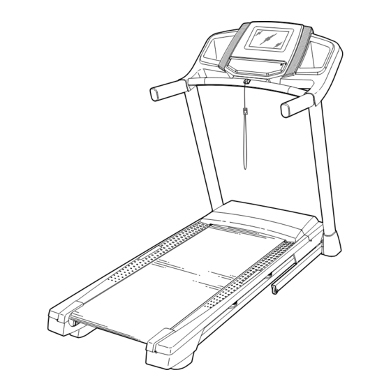
Model No. NTL17919-INT.0
Serial No.
Write the serial number in the space
above for reference.
Serial
Number
Decal
CUSTOMER SERVICE
UNITED KINGDOM
Call: 0330 123 1045
From Ireland: 053 92 36102
Website: iconsupport.eu
E-mail: csuk@iconeurope.com
Write:
ICON Health & Fitness, Ltd.
Unit 4, Westgate Court
Silkwood Park
OSSETT
WF5 9TT
UNITED KINGDOM
AUSTRALIA
Call: 1800 993 770
E-mail: australiacc@iconfitness.com
Write:
ICON Health & Fitness, Inc.
PO Box 635
WINSTON HILLS NSW 2153
AUSTRALIA
CAUTION
Read all precautions and
instructions in this manual before
using this equipment. Save this
manual for future reference.
USER'S MANUAL
iconeurope.com
Advertisement
Table of Contents

Related Manuals for NordicTrack NTL17919-INT.0


Summary of Contents for NordicTrack NTL17919-INT.0
- Page 1 Model No. NTL17919-INT.0 Serial No. USER’S MANUAL Write the serial number in the space above for reference. Serial Number Decal CUSTOMER SERVICE UNITED KINGDOM Call: 0330 123 1045 From Ireland: 053 92 36102 Website: iconsupport.eu E-mail: csuk@iconeurope.com Write: ICON Health & Fitness, Ltd.
-
Page 2: Table Of Contents
Note: The decals may not be shown at actual size. 305284 NORDICTRACK and IFIT are registered trademarks of ICON Health & Fitness, Inc. Wi-Fi is a registered trade- mark of Wi-Fi Alliance. WPA and WPA2 are trademarks of Wi-Fi Alliance. The Bluetooth word mark and logos ®... -
Page 3: Important Precautions
IMPORTANT PRECAUTIONS WARNING: To reduce the risk of burns, fire, electric shock, or injury to persons, read all important precautions and instructions in this manual and all warnings on your treadmill before using your treadmill. ICON assumes no responsibility for personal injury or property damage sus- tained by or through the use of this product. - Page 4 20. Keep fingers, hair, and clothing away from 24. Do not change the incline of the treadmill by the moving walking belt.The treadmill is placing objects under the treadmill. capable of high speeds. Adjust the speed in small increments to avoid sudden jumps in 25.
-
Page 5: Before You Begin
BEFORE YOU BEGIN Thank you for selecting the new NORDICTRACK manual. To help us assist you, note the product model ® T 6.5 SI treadmill. The T 6.5 SI treadmill provides an number and serial number before contacting us. The... -
Page 6: Part Identification Chart
PART IDENTIFICATION CHART Use the drawings below to identify small parts used for assembly. The number in parentheses below each draw- ing is the key number of the part, from the PART LIST near the end of this manual. The number following the key number is the quantity used for assembly. -
Page 7: Assembly
ASSEMBLY • Assembly requires two persons. • To identify small parts, see page 6. • Place all parts in a cleared area and remove the • Assembly requires the following tools: packing materials. Do not dispose of the packing the included hex keys materials until you finish all assembly steps. - Page 8 2. Make sure that the power cord is unplugged. Remove the tie securing the Upright Wire (81) to the front of the Base (6). Next, identify the Right Upright (90). Have a second person hold the Right Upright near the Base (6).
- Page 9 4. Hold the Right Upright (90) against the Base (6). Do not pinch the Upright Wire (81). Attach the Right Upright (90) with two 3/8" x 2 3/8" Screws (7), a 3/8" x 1 1/4" Screw (63), a 3/8" x 1 3/4" Screw (62), and four 3/8" Star Washers (13) as shown;...
- Page 10 6. If there are four screws (E) preattached inside the Handrails (84), remove and discard the screws (only one side is shown). Identify the Right Handrail (84). Attach the Right Handrail (84) to the Right Upright (90) with two 5/16" x 3" Screws (28) and two 5/16"...
- Page 11 8. IMPORTANT: To avoid damaging the Handrail Crossbar (23), do not use power tools and do not overtighten the #10 x 1 1/4" Screws (9). Orient the Handrail Crossbar (23) as shown. Attach the Handrail Crossbar to the Handrails (84, 85) with four #10 x 1 1/4" Screws (9) and four #10 Star Washers (5);...
- Page 12 10. Set the console assembly (G) on the Right and Left Handrails (84, 85). Make sure that no wires are pinched. Insert the excess Upright Wire (81) into the Right Upright (90). Attach the console assembly (G) with four 1/4" x 1/2"...
- Page 13 12. Raise the Frame (56) to the upright position. Have a second person hold the Frame until step 14 is completed. Remove the two 5/16" x 3/4" Screws (8) from the Latch Crossbar (41). Orient the Latch Crossbar (41) as shown. Make sure that the “This side toward belt”...
- Page 14 14. Remove the 5/16" Nut (34) and the 5/16" x 2 1/4" Bolt (31) from the bracket on the Latch Crossbar (41). Align the upper end of the Storage Latch (26) with the bracket on the Latch Crossbar (41), and insert the 5/16"...
-
Page 15: How To Use The Incline Trainer
HOW TO USE THE TREADMILL HOW TO PLUG IN THE POWER CORD Follow the steps below to plug in the power cord. This product must be earthed. If it should malfunc- 1. Plug the indicated end of the power cord (A) into the tion or break down, earthing provides a path of least socket on the treadmill (B). - Page 16 CONSOLE DIAGRAM FEATURES OF THE CONSOLE rate using a compatible heart rate monitor. See page 27 for information about purchasing an optional heart rate monitor. The advanced treadmill console offers a selection of features designed to make your workouts more effec- tive and enjoyable.
- Page 17 HOW TO TURN ON THE POWER HOW TO USE THE TOUCH SCREEN IMPORTANT: If the treadmill has been exposed to The console features a tablet with a full-color touch cold temperatures, allow it to warm to room tem- screen. The following information will help you become perature before you turn on the power.
- Page 18 HOW TO SET UP THE CONSOLE 5. Calibrate the incline system. Before using the treadmill for the first time, set up the First, touch your name or Hello on the screen. console. Next, select the settings main menu. Then, select the maintenance section, touch Calibrate Incline, 1.
- Page 19 HOW TO USE THE MANUAL MODE 3. Start the walking belt and adjust the speed. 1. Insert the key into the console. Touch Manual Start on the screen or press the Start button on the console to start the walking belt. See HOW TO TURN ON THE POWER on page 17.
- Page 20 5. Monitor your progress with the display modes. 6. When you are finished exercising, remove the key from the console. While you walk or run on the treadmill, a selection of workout information will be displayed, such as: Step onto the foot rails and press the Stop button on the console or tap on the screen.
- Page 21 HOW TO USE A MAP WORKOUT 4. Start the workout. Note: To use a map workout, the console must be con- Touch Start to start the workout. A moment after nected to a wireless network (see HOW TO CONNECT you touch the button, the walking belt will begin to TO A WIRELESS NETWORK on page 26).
- Page 22 HOW TO USE A DRAW YOUR OWN MAP 4. Save your workout. WORKOUT Touch Save New Workout on the screen. If desired, Note: To use a draw your own map workout, the change the title of the workout or add a description, console must be connected to a wireless network (see and then press the >...
- Page 23 HOW TO USE A DISTANCE OR TIME WORKOUT 5. Select a distance or time workout that you have previously added to your schedule on iFit.com. Note: To use a distance or time workout, the console must be connected to a wireless network (see HOW Touch the calendar icon to download a distance or TO CONNECT TO A WIRELESS NETWORK on time workout from your schedule.
- Page 24 HOW TO CHANGE CONSOLE SETTINGS 2. Navigate the settings menus and change settings as desired. IMPORTANT: Some of the settings and features described may not be enabled. Occasionally, a Slide or flick the screen to scroll upward or down- firmware update may cause your console to function ward if necessary.
- Page 25 5. Update the console firmware. 6. Calibrate the incline system of the treadmill. For the best results, regularly check for Touch Calibrate Incline, and then touch Begin firmware updates. Touch Maintenance, and then to calibrate the incline system. The treadmill will touch Update to check for firmware updates using automatically rise to the maximum incline level, and your wireless network.
- Page 26 HOW TO CONNECT TO A WIRELESS NETWORK An information box will ask if you want to connect to the wireless network. Touch Connect to connect The console is Wi-Fi enabled, allowing you to set up a to the network or touch Cancel to return to the list wireless network connection.
- Page 27 HOW TO USE THE SOUND SYSTEM HOW TO ADJUST THE CUSHIONING SYSTEM To play music or audio books through the console The treadmill features a cushioning system that sound system while you exercise, plug a 3.5 mm male reduces the impact as you walk or run on the treadmill. to 3.5 mm male audio cable (not included) into the jack on the console and into a jack on your personal To adjust the cushions, first remove the key from the...
-
Page 28: How To Fold And Move The Treadmill
HOW TO FOLD AND MOVE THE TREADMILL HOW TO FOLD THE TREADMILL HOW TO MOVE THE TREADMILL To avoid damaging the treadmill, adjust the incline Before moving the treadmill, fold it as described at the to zero before you fold the treadmill. Then, remove left. -
Page 29: Maintenance And Troubleshooting
MAINTENANCE AND TROUBLESHOOTING MAINTENANCE c. Check the power switch located on the treadmill frame near the power cord. If the switch protrudes Regular maintenance is important for optimal per- as shown, the switch has tripped. To reset the formance and to reduce wear. Inspect and properly power switch, wait for five minutes and then press tighten all parts each time the treadmill is used. - Page 30 SYMPTOM: The displays of the console do not SYMPTOM: The treadmill will not connect to the function properly wireless network a. Remove the key from the console and UNPLUG a. Make sure that the wireless settings on the console THE POWER CORD. Next, remove the five #8 x are correct (see page 26).
- Page 31 SYMPTOM: The walking belt slows when walked on SYMPTOM: The walking belt is not centered between the foot rails a. If an extension cord is needed, use only a 3-conduc- tor, 14-gauge (2 mm ) cord that is no longer than The edges of the walking belt should be aligned with 5 ft.
-
Page 32: Exercise Guidelines
EXERCISE GUIDELINES Aerobic Exercise—If your goal is to strengthen your WARNING: cardiovascular system, you must perform aerobic Before beginning this exercise, which is activity that requires large amounts or any exercise program, consult your physi- of oxygen for prolonged periods of time. For aerobic cian. - Page 33 SUGGESTED STRETCHES The correct form for several basic stretches is shown at the right. Move slowly as you stretch —never bounce. 1. Toe Touch Stretch Stand with your knees bent slightly and slowly bend forward from your hips. Allow your back and shoulders to relax as you reach down toward your toes as far as possible.
-
Page 34: Part List
PART LIST Model No. NTL17919-INT.0 R0421A Key No. Qty. Description Key No. Qty. Description #8 x 5/8" Screw 3/8" Plastic Bushing #8 x 3/4" Screw 3/8" Washer Ground Screw 1/4" x 1 1/4" Screw 1/4" x 1/2" Screw Drive Motor... - Page 35 Key No. Qty. Description Key No. Qty. Description #8 x 3/4" Truss Head Screw Filter Clip Motor Bushing Magnet Motor Isolator Reed Switch 9/32" Plastic Bushing #8 Nut Base Pad #8 x 1/2" Machine Screw – User’s Manual Note: Specifications are subject to change without notice. For information about ordering replacement parts, see the back cover of this manual.
-
Page 36: Exploded Drawing
EXPLODED DRAWING A Model No. NTL17919-INT.0 R0421A... - Page 37 EXPLODED DRAWING B Model No. NTL17919-INT.0 R0421A...
- Page 38 EXPLODED DRAWING C Model No. NTL17919-INT.0 R0421A...
- Page 39 EXPLODED DRAWING D Model No. NTL17919-INT.0 R0421A...
-
Page 40: Ordering Replacement Parts
ORDERING REPLACEMENT PARTS To order replacement parts, please see the front cover of this manual. To help us assist you, be prepared to provide the following information when contacting us: • the model number and serial number of the product (see the front cover of this manual) •...