Table of Contents
Advertisement
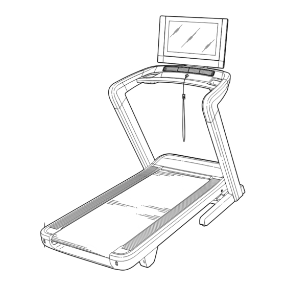
Model No. NTL17122-INT.0
Serial No.
Write the serial number in the space
above for reference.
Serial Number
Decal
MEMBER CARE
UNITED KINGDOM
Call: 0330 123 1045
From Ireland: 053 92 36102
Website: iconsupport.eu
E-mail: csuk@iconeurope.com
Write:
ICON Health & Fitness, Ltd.
Unit 4, Westgate Court
Silkwood Park
OSSETT
WF5 9TT
UNITED KINGDOM
AUSTRALIA
Call: 1800 993 770
E-mail: australiacc@iconfitness.com
Write:
iFIT Inc.
PO Box 635
WINSTON HILLS NSW 2153
AUSTRALIA
CAUTION
Read all precautions and
instructions in this manual before
using this equipment. Keep this
manual for future reference.
USER'S MANUAL
iconeurope.com
Advertisement
Table of Contents

Related Manuals for NordicTrack NTL17122-INT.0


Summary of Contents for NordicTrack NTL17122-INT.0
- Page 1 Model No. NTL17122-INT.0 Serial No. USER’S MANUAL Write the serial number in the space above for reference. Serial Number Decal MEMBER CARE UNITED KINGDOM Call: 0330 123 1045 From Ireland: 053 92 36102 Website: iconsupport.eu E-mail: csuk@iconeurope.com Write: ICON Health & Fitness, Ltd.
-
Page 2: Table Of Contents
The decals may not be shown at actual size. 305284 NORDICTRACK and IFIT are registered trademarks of iFIT Inc. Google Maps is a trademark of Google LLC. The Bluetooth word mark and logos are registered trademarks of Bluetooth SIG, Inc. and are used under license. -
Page 3: Important Precautions
IMPORTANT PRECAUTIONS WARNING: To reduce the risk of burns, fire, electric shock, or injury to persons, read all important precautions and instructions in this manual and all warnings on your treadmill before using your treadmill. iFIT assumes no responsibility for personal injury or property damage sus- tained by or through the use of this product. - Page 4 20. When a person is walking on the treadmill, 26. Do not change the incline of the treadmill by the noise level of the treadmill will increase. placing objects under the treadmill. 21. Keep fingers, hair, and clothing away from 27.
-
Page 5: Before You Begin
BEFORE YOU BEGIN Thank you for selecting the new NORDICTRACK reading this manual, please see the front cover of this ® COMMERCIAL 2450 treadmill. The COMMERCIAL manual. To help us assist you, note the product model 2450 treadmill provides an impressive selection of fea- number and serial number before contacting us. -
Page 6: Part Identification Chart
PART IDENTIFICATION CHART Use the drawings below to identify small parts used for assembly. The number in parentheses below each draw- ing is the key number of the part, from the PART LIST near the end of this manual. The number following the key number is the quantity used for assembly. -
Page 7: Assembly
ASSEMBLY • Assembly requires two persons. • To identify small parts, see page 6. • Place all parts in a cleared area and remove the • Assembly requires the following tools: packing materials. Do not dispose of the packing the included hex keys materials until you finish all assembly steps. - Page 8 2. Make sure that the power cord is unplugged. Identify the Right Upright (114), and lay it near the Base (118) as shown. Next, connect the Belly Pan Wire (96) to the Upright Wire (120) in the Right Upright (114). The connectors should slide together eas- ily and snap into place with an audible click.
- Page 9 4. Do not pinch the Wires (119, 120) during this step. With the help of a second person, hold the handrail assembly (D) on the Left and Right Uprights (113, 114). Attach the handrail assembly with four 3/8" x 2 3/4" Screws (2) and four 3/8"...
- Page 10 6. Identify the Right Inner Grip (102), and attach it to the right side of the handrail assembly (D) with four #8 x 3/4" Screws (4); start all four Screws, and then tighten them. Do not overtighten the Screws. Attach the Left Inner Grip (101) to the left side of the handrail assembly (D) in the same way.
- Page 11 8. Have a second person hold the console assem- bly (E) near the handrail assembly (D). Connect the wires (F) from the console assembly (E) to the wires (G) from the handrail assembly (D). The connectors should slide together easily and snap into place with an audible click.
- Page 12 10. Rotate the console assembly (E) back to its original position. Firmly tighten the two M6 x 25mm Screws (8) that you attached in step 8. Next, identify the Right Pivot Cover (137). Attach the Right Pivot Cover to the Console Pivot Bracket (138) with an M4 x 20mm Screw (6);...
- Page 13 12. Note: If the treadmill is assembled on a smooth surface, it may roll forward during this step. Raise the Frame (74) to the position shown. IMPORTANT: Do not raise the Frame past the vertical position. Have a second person hold the Frame until step 14 is completed.
- Page 14 14. Remove the 5/16" Nut (49) and the 5/16" x 2 1/4" Bolt (27) from the bracket on the Latch Crossbar (76). 49 K Next, align the upper end of the Storage Latch (75) with the bracket on the Latch Crossbar (76), and insert the 5/16"...
- Page 15 16. See HOW TO CONNECT THE POWER CORD on page 16, and plug in the power cord. Then, see HOW TO USE THE MANUAL MODE on page 20, and adjust the incline of the treadmill to 10%. Next, identify the Right Base Cover (121). Position the large cutout (I) in the Right Base Cover around the Right Upright (114), and slide the Right Base Cover downward onto the Base...
-
Page 16: How To Use The Treadmill
HOW TO USE THE TREADMILL HOW TO PLUG IN THE POWER CORD Follow the steps below to plug in the power cord. This product must be earthed. If it should malfunc- 1. Plug the indicated end of the power cord (A) into the tion or break down, earthing provides a path of least socket on the treadmill (B). - Page 17 CONSOLE DIAGRAM FEATURES OF THE CONSOLE When you use the manual mode of the console, you can change the speed and incline of the treadmill with The advanced treadmill console offers a selection of the touch of a button. As you exercise, the console will features designed to make your workouts more effec- display instant exercise feedback.
- Page 18 HOW TO TURN ON THE POWER HOW TO USE THE TOUCH SCREEN IMPORTANT: If the treadmill has been exposed to The console features a tablet with a full-color touch cold temperatures, allow it to warm to room tem- screen. The following information will help you become perature before you turn on the power.
- Page 19 HOW TO SET UP THE CONSOLE 5. Calibrate the incline system. Before using the treadmill for the first time, set up the First, touch the menu button (three horizontal lines symbol), touch Settings, touch Maintenance, touch console. Calibrate Incline, and then touch Begin to calibrate 1.
- Page 20 HOW TO USE THE MANUAL MODE 4. Change the incline of the treadmill as desired. 1. Insert the key into the console. To change the incline of the treadmill, press the incline increase and decrease buttons or one of the See HOW TO TURN ON THE POWER on page 18.
- Page 21 6. Turn on the fan if desired. HOW TO USE A FEATURED WORKOUT The fan features several Note: To use a featured workout, the console must speed settings. Press the be connected to a wireless network (see HOW TO fan buttons repeatedly to CONNECT TO A WIRELESS NETWORK on page 27).
- Page 22 4. Start the workout. To end the workout, touch the screen to pause the workout, and then follow the prompts on the screen Touch Start Workout to start the workout. to end the workout and return to the home screen. During some workouts, an iFIT coach will guide When the workout ends, a workout summary will you through a video workout.
- Page 23 HOW TO CREATE A DRAW-YOUR-OWN-MAP 4. Save your workout. WORKOUT Touch Save New Workout on the screen. If desired, Note: To create a draw-your-own-map workout, the change the title of the workout or add a description. console must be connected to a wireless network (see HOW TO CONNECT TO A WIRELESS NETWORK on 5.
- Page 24 HOW TO USE AN IFIT WORKOUT 4. Select an iFIT workout that you have previously added to your schedule on iFIT.com. To use an iFIT workout, the console must be connected IMPORTANT: Before iFIT workouts will load, to a wireless network (see HOW TO CONNECT TO A you must add them to your schedule on WIRELESS NETWORK on page 27).
- Page 25 HOW TO CHANGE CONSOLE SETTINGS 3. Customize the time zone and other settings. IMPORTANT: Some of the settings and features To customize the time zone or other settings, touch described may not be enabled. Occasionally, a Equipment Settings and then touch the desired firmware update may cause your console to function settings.
- Page 26 6. Calibrate the incline system of the treadmill. IMPORTANT: Keep pets, feet, and other objects away from the treadmill while the incline Touch Calibrate Incline, and then touch Begin to system is calibrating. In an emergency, pull the key from the console to stop the incline calibrate the incline system.
- Page 27 HOW TO CONNECT TO A WIRELESS NETWORK When the console is connected to your wireless network, a checkmark will appear next to the wire- The console is Wi-Fi enabled, allowing you to set up a less network name. wireless network connection. To disconnect from a wireless network, touch and 1.
-
Page 28: How To Fold And Move The Treadmill
HOW TO FOLD AND MOVE THE TREADMILL HOW TO FOLD THE TREADMILL HOW TO MOVE THE TREADMILL To avoid damaging the treadmill, adjust the incline Before moving the treadmill, fold it as described at the to zero before you fold the treadmill. Then, remove left. -
Page 29: Maintenance And Troubleshooting
MAINTENANCE AND TROUBLESHOOTING MAINTENANCE c. Check the power switch located on the treadmill frame near the power cord. If the switch protrudes Regular maintenance is important for optimal per- as shown (A), the switch has tripped. To reset the formance and to reduce wear. Inspect and properly power switch, wait for five minutes and then press tighten all parts each time the treadmill is used. - Page 30 SYMPTOM: The walking belt slows when walked on c. Your treadmill features a walking belt coated with high-performance lubricant. IMPORTANT: Never a. If an extension cord is needed, use only a 3-conduc- apply silicone spray or other substances to the walking belt or the walking platform unless tor, 14-gauge (2 mm ) cord that is no longer than instructed to do so by an authorized service...
- Page 31 b. If the walking belt slips when walked on, first SYMPTOM: The displays of the console do not remove the key and UNPLUG THE POWER function properly CORD. Using the hex key, turn both idler roller screws clockwise, 1/4 of a turn. When the walking a.
-
Page 32: Exercise Guidelines
EXERCISE GUIDELINES Aerobic Exercise—If your goal is to strengthen your WARNING: cardiovascular system, you must perform aerobic Before beginning this exercise, which is activity that requires large amounts or any exercise program, consult your physi- of oxygen for prolonged periods of time. For aerobic cian. - Page 33 SUGGESTED STRETCHES The correct form for several basic stretches is shown at the right. Move slowly as you stretch —never bounce. 1. Toe Touch Stretch Stand with your knees bent slightly and slowly bend forward from your hips. Allow your back and shoulders to relax as you reach down toward your toes as far as possible.
-
Page 34: Part List
PART LIST Model No. NTL17122-INT.0 R0122A Key No. Qty. Description Key No. Qty. Description 3/8" x 1 1/4" Screw Clip 3/8" x 2 3/4" Screw M25 Nut Incline Stop Bracket M10 Nut #8 x 3/4" Screw 1/2" Plastic Bushing Ground Screw... - Page 35 Key No. Qty. Description Key No. Qty. Description Left Inner Grip Lower Console Cover Right Inner Grip Console Back Plate Right Outer Grip Saddle Bracket Right Upright Inner Cover Pivot Cover Right Inner Console Base Cover Console Left Handrail Right Handrail Pivot Front Cover Console Crossbar Pivot Back Cover...
-
Page 36: Exploded Drawing
EXPLODED DRAWING A Model No. NTL17122-INT.0 R0122A... - Page 37 EXPLODED DRAWING B Model No. NTL17122-INT.0 R0122A...
- Page 38 EXPLODED DRAWING C Model No. NTL17122-INT.0 R0122A...
- Page 39 EXPLODED DRAWING D Model No. NTL17122-INT.0 R0122A...
-
Page 40: Ordering Replacement Parts
ORDERING REPLACEMENT PARTS To order replacement parts, please see the front cover of this manual. To help us assist you, be prepared to provide the following information when contacting us: • the model number and serial number of the product (see the front cover of this manual) •...