Table of Contents
Advertisement
Available languages
Available languages
Quick Links
NATURAL GAS MODELS:
PROPANE GAS MODELS:
SAFETY INFORMATION
WARNING
!
FIRE OR EXPLOSION HAZARD
Failure to follow safety warnings exactly
could result in serious injury, death, or
property damage.
- Do not store or use gasoline or other
fl ammable vapors and liquids in the vicinity of
this or any other appliance.
- WHAT TO DO IF YOU SMELL GAS:
•
Do not try to light any appliance.
•
Do not touch any electrical switch; do not
use any phone in your building.
•
Immediately call your gas supplier from a
neighbour's phone. Follow the gas
supplier's instructions.
•
If you cannot reach your gas supplier, call
the fi re department.
- Installation and service must be
performed by a qualifi ed installer, service
agency, or the supplier.
This appliance may be installed in an aftermarket,
permanently located, manufactured home (USA
only) or mobile home, where not prohibited by
local codes.
This appliance is only for use with the type of gas
indicated on the rating plate. This appliance is
not convertible for use with other gases, unless
a certifi ed kit is used.
INSTALLER:
Leave this manual with the appliance
CONSUMER:
Retain this manual for future reference
Wolf Steel Ltd., 24 Napoleon Rd., Barrie, ON, L4M 0G8 Canada / 103 Miller Drive, Crittenden, Kentucky, USA, 41030
$10.00
GDS50N / GS50N
ADD PRODUCT CODE HERE (TRADE GOTHIC LT STD FONT)
GDS50P / GS50P
Phone 1 (866) 820-8686 • www.napoleon.com • hearth@napoleon.com
INSTALLATION AND
ADD MANUAL TITLE
OPERATION MANUAL
CERTIFIED TO THE CANADIAN AND AMERICAN NATIONAL STANDARDS:
CSA 2.22 AND ANSI Z21.50 FOR VENTED DECORATIVE GAS APPLIANCES
IF INSTALLATION + OPERATION, ADD SERIAL
CSA /
INTERTEK
BARCODE LABEL ON THE OWNER'S MANUAL"
LOGO
Product Name / Code
(MUST use title from Price Book)
ADD ____ ILLUSTRATED
ADD PRODUCT IMAGE
Model GS50 is made up of Model GDS50 and
Natural Vent Adapter Kit GS-150KT
FOR INDOOR USE ONLY
NUMBER LABEL HERE
IF SEPARATE MANUALS, ADD "PLACE
ENGLISH
FRENCH PG. 49
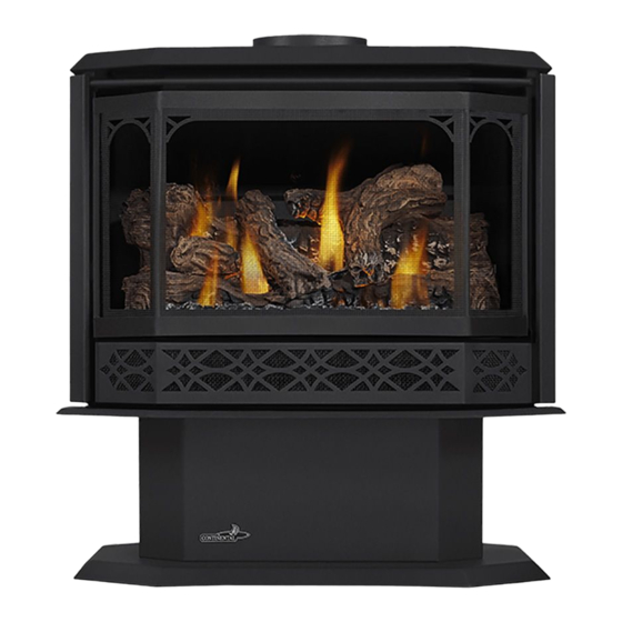
Havelock™
(GDS50 illustrated)
W415-1427 / C / 06.05.19
Advertisement
Chapters
Table of Contents

Related Manuals for Napoleon Havelock


Summary of Contents for Napoleon Havelock
- Page 1 INTERTEK BARCODE LABEL ON THE OWNER’S MANUAL” LOGO Wolf Steel Ltd., 24 Napoleon Rd., Barrie, ON, L4M 0G8 Canada / 103 Miller Drive, Crittenden, Kentucky, USA, 41030 Phone 1 (866) 820-8686 • www.napoleon.com • hearth@napoleon.com $10.00 W415-1427 / C / 06.05.19...
- Page 2 safety information WARNING DANGER • This appliance is hot when operated and can cause severe burns if contacted. • Any changes or alterations to this appliance or its controls can be dangerous and is prohibited. HOT GLASS WILL CAUSE BURNS. •...
- Page 3 safety information WARNING • Do not use a blower insert, heat exchanger insert or other accessory not approved for use with this appliance. • This appliance must not be connected to a chimney fl ue pipe serving a separate solid fuel burning appliance.
-
Page 4: Table Of Contents
table of contents finishing general information safety barrier and door installation / rates and effi ciencies removal general instructions log placement rating plate information logo placement dimensions trivet installation mobile home installation operation venting operating instructions typical vent installation turbo burner operation special vent installations spill switch - GS50 only 2.2.1 periscope termination... -
Page 5: Rates And Effi Ciencies
standard checklist Installer, please fi ll out the following information: Customer: _____________________________________________________________________ Address: _____________________________________________________________________ Date of Installation: _____________________________________________________________________ Location of Appliance: _____________________________________________________________________ Installer: _____________________________________________________________________ Dealer/Distributor Contact Number: _____________________________________________________________________ Serial #: _____________________________________________________________________ Model: Natural Gas: Propane: GDS50-1NSB GDS50-1PSB GS50N GS50P 1.0 general information For elevations between 2,000ft (610m) and 4,500ft (1372m) above sea level, this appliance must be de-rated by 10% using the certifi... -
Page 6: General Information
general information general instructions WARNING • Always light the pilot, whether for the fi rst time or if the gas supply has run out, with the glass door opened or removed. • Provide adequate clearance for servicing and operating the appliance. •... -
Page 7: Rating Plate Information
Les longeurs horizontales minimale et maximale sont 25 pouces et Les longeurs horiz eurs ho L’appareil doit être ventilé à l’aide de l’ensemble d’évacuation propre à Napoleon. Référez au 20 pieds respectivement. 20 pieds re manuel d’installation pour les spécifications d’évacuation. Il est nécessaire de bien réinstaller et This appliance must be installed using an adapter kit GS-150KT. -
Page 8: Venting
venting 2.0 venting WARNING • Risk of fi re. Maintain specifi ed air space clearances to vent pipe and appliance. • The vent system must be supported every 3’(0.9m) for both vertical and horizontal runs. Use support ring assembly W010- 0067 or equivalent non-combustible strapping to maintain the minimum clearance to combustibles for both vertical and horizontal runs. -
Page 9: Typical Vent Installation
venting Horizontal runs may have a 0” rise per foot or 0mm rise per meter however for optimum performance it is recommended that all horizontal runs have a minimum 1/4” rise per foot or 21mm rise per meter using fl exible venting. For safe and proper operation of the appliance, follow the venting instructions exactly. -
Page 10: Special Vent Installations
venting special vent installations 2.2.1 periscope termination Use the periscope kit to locate the air termination above grade. The periscope must be installed so that when fi nal grading is completed, the bottom air slot is located a minimum 12” (305mm) above grade. The maximum allowable vent length (including both rise and run) is 10’... -
Page 11: Vent Terminal Clearances
venting vent terminal clearances Covered balcony applications ††* = 3 feet = 2 x ACTUAL (0.9m) (4.6m) note: INSTALLATIONS Wall terminals are for illustration purposes only. Size and shapes may vary. CANADA U.S.A. 12” (30.5cm) 12” (30.5cm) Clearance above grade, veranda porch, deck or balcony. Δ... -
Page 12: Venting Application Fl Ow Chart
venting venting application fl ow chart Top Exit Horizontal Termination Vertical Termination Vertical rise is equal Vertical rise is equal Vertical rise is less Vertical rise is less to or greater than the to or greater than the than horizontal run than horizontal run horizontal run horizontal run... -
Page 13: Horizontal Termination
venting horizontal termination ) < (V Simple venting confi guration (only one 90° elbow) See graph to determine the required vertical rise V for the required horizontal run H 40 (12.2) 39 (11.9) REQUIRED 30 (9.1) VERTICAL RISE IN FEET 20 (6.1) (METERS)V 10 (3.1) - Page 14 venting ) > (V See graph to determine the required vertical rise V for the Simple venting configuration (only one 90° elbow) required horizontal run H 150 (3810) REQUIRED VERTICAL RISE 100 (2540) IN INCHES (MILLIMETERS)V 50 (1270) 29 (736.6) (1.5) (4.6) (3.1)
-
Page 15: Vertical Termination
venting vertical termination ) < (V Simple venting configurations. See graph to determine the required vertical rise V for the required horizontal run H 40 (12.2) 30 (9.1) REQUIRED VERTICAL RISE IN FEET 20 (6.1) (METERS) V 10 (3.1) 3 (0.9) (1.5) (3.1) (4.6) - Page 16 venting ) > (V Simple venting configurations. See graph to determine the required vertical rise V for the required horizontal run H 20 (6.1) 19 (5.8) REQUIRED VERTICAL RISE IN FEET 10 (3.1) (METERS) V 3 (0.9) (7.6) (9.1) (1.5) (3.1) (4.6) (6.1)
-
Page 17: Vertical Through Existing Chimney
venting vertical through existing chimney WARNING • Risk of fi re. • Co-axial to co-linear venting confi gurations must only be used in a non-combustible chimney or enclosure. Installation in a combustible enclosure could result in a fi re. This appliance is designed to be attached to a 3” (76.2mm) co-linear aluminum fl ex vent system running the full length of a masonry chimney. -
Page 18: Installation
installation 3.0 installation WARNING • Ensure to unpack all loose materials from inside the fi rebox prior to connecting the gas and electrical supply • If your appliance is supplied with a remote, ensure the remote receiver is in the “OFF” position prior to connecting the gas and electrical supply to the appliance. -
Page 19: Horizontal Installation - Gds50
installation 3.1.1 horizontal installation - GDS50 WARNING • The fi restop assembly must be installed with the vent shield to the top. • Terminals must not be recessed into a wall or siding more than the depth of the return fl ange of the mounting plate. -
Page 20: Vertical Installation
installation 3.1.2 vertical installation This application occurs when venting through a roof. Installation kits for various roof pitches are available from your authorized dealer / distributor. See the “accessories” section to order specifi c kits required. A. Determine the air terminal location, cut and frame a square opening, as illustrated, in the ceiling and the roof to provide the minimum 1"... -
Page 21: Horizontal Air Terminal Installation
installation 3.1.3 horizontal air terminal installation WARNING • Terminals must not be recessed into a wall or siding more than the depth of the return fl ange of the mounting plate. • Do not allow the inner fl ex pipe to bunch up on horizontal or vertical runs and elbows. Keep it pulled tight. •... -
Page 22: Vertical Air Terminal Installation
installation 3.1.4 vertical air terminal installation WARNING • Maintain a minimum 2” (51mm) space between the air inlet base and the storm collar. note: Fastening hardware provided with appropriate roof terminal and liner kits. Fasten the roof support to the roof using 6 screws. The roof support is optional. -
Page 23: Appliance Vent Connection
installation 3.1.5 appliance vent connection Attach the adjustable pipe to the last section of rigid pipe. Secure with screws and seal. #8 X 1/2” Self Drilling Install the inner fl ex pipe to the appliance. Secure with a minimum of Screws INSERT three screws and fl... -
Page 24: B-Vent Installation - Gs50
installation B-vent installation - GS50 3.2.1 chimney installation WARNING • A chimney venting this appliance shall not vent any solid fuel burning appliance. Three types of chimney systems may be used with this appliance. “B” VENT GAS “A” VENT - SOLID MASONRY CLAY BURNING FUEL WOOD BURNING... -
Page 25: Installing Natural Vent
installation 3.2.3 installing natural vent ADAPTER INSTALLATION: • Remove the spill switch bracket from the rear of the adapter. • Gently pull the two wire terminals (located inside the 7" (178mm) fl ue collar at the top of the appliance) out ADAPTER approximately 8"... -
Page 26: Natural Vent - Model Gs50
installation 3.2.5 natural vent - model GS50 Attach one lead from the spill switch (white wire) to terminal #3 located on the gas valve and the other (black) on/ off switch lead to valve terminal #1. Attach the B-Vent label, as illustrated, in the control area of the appliance. ATTACH THIS LABEL IN THE CONTROL AREA OF THE APPLIANCE. -
Page 27: Adding Vent Sections
installation 3.2.7 adding vent sections Add chimney sections, according to the manufacturer’s installation instructions. If the chimney system passes through an attic space, a rafter radiation shield or attic insulation shield is required. The chimney must extend at least 3ft (0.9m) above its point of contact with the roof and at least 2ft (0.6m) higher than any wall, roof or building within 10ft (3.1m). -
Page 28: Gas Installation
4.0 gas installation gas installation WARNING • Risk of fi re, explosion, or asphyxiation. Ensure there are no ignition sources such as sparks or open fl ames. • Support gas control when attaching gas supply pipe to prevent damaging gas line. •... -
Page 29: Finishing
6.0 fi nishing fi nishing safety barrier and door installation / removal WARNING • Glass may be hot. Do not touch glass until cooled. • If equipped with door latches that are part of a safety system, they must be properly engaged. Do not operate the appliance with latches disengaged. - Page 30 fi nishing SAFETY SCREEN SAFETY SCREEN When opening the fi re viewing door, a simple procedure must be followed in order to not damage the door. First open the valve control door. Next open both side doors fully. Pull the latch handles towards you and release each catch.
-
Page 31: Log Placement
fi nishing log placement WARNING • Failure to position the logs in accordance with these diagrams or failure to use only logs specifi cally approved with this appliance may result in property damage or personal injury. • Logs must be placed in their exact location in the appliance. Do not modify the proper log positions, since appliance may not function properly and delayed ignition may occur. -
Page 32: Logo Placement
fi nishing logo placement Remove the backing of the logo supplied and centre over the logo installation holes, as indicated. trivet installation Insert the trivet into the space on the appliance top. Line up the holes in the brackets, and secure using the screw BRACKET provided. -
Page 33: Operation
7.0 operation operation WARNING • If you do not follow these instructions exactly, a fi re or explosion may result causing property damage, personal injury, or loss of life. • If applicable, always light the pilot whether for the fi rst time or if the gas supply has run out with the glass door opened or removed. -
Page 34: Operating Instructions
operation operating instructions The on-off switch is located on the back of the appliance at the top left corner on models GDS50 and GS50. turbo burner operation The purpose of the turbo burner is to increase heat output of BTUs of the appliance and will only operate when the main burner is functioning. -
Page 35: Adjustments
8.0 adjustments adjustments pilot burner adjustment Adjust the pilot screw to provide properly sized fl ame. Turn in a clockwise direction to reduce the gas fl ow. Check Pressure Readings: Inlet pressure can be checked by turning screw (A) counter- clockwise 2 or 3 turns and then placing pressure gauge tubing over the test point. -
Page 36: Fl Ame Characteristics
adjustments fl ame characteristics 3/8” - 1/2” It’s important to periodically perform a visual check of (9.5mm - 12.7mm) the pilot and burner flames. Compare them to the ADD IMAGE illustration provided. If any flames appear abnormal, Flame must envelop call a service person. -
Page 37: Annual Maintenance
maintenance annual maintenance WARNING • Annual maintenance should be performed by a qualifi ed service technician • The fi rebox becomes very hot during operation. Let the appliance cool completely or wear heat resistant gloves before conducting service. • Never vacuum hot embers. •... -
Page 38: Replacement Blower Installation
maintenance replacement blower installation RELIEF DOOR GASKET RELIEF DOOR TWIN BLOWER VARIABLE THERMODISC SPEED SWITCH Turn off the electrical power and the gas supply to the appliance. Open the lower louvre control door, the two side doors and the fi re viewing door. Remove the logs. Remove the relief door assembly held on with 6 screws. -
Page 39: Care Of Glass
maintenance care of glass WARNING • Do not clean glass when hot! Do not use abrasive cleaners to clean glass. Buff lightly with a clean dry soft cloth to remove accumulated dust or fi ngerprints. Clean both sides of the glass after the fi... -
Page 40: Replacement Parts
10.0 replacement parts replacement parts WARNING • Failure to position the parts in accordance with this manual or failure to use only parts specifi cally approved with this appliance may result in property damage or personal injury. Contact your dealer for questions concerning prices and policies on replacement parts. Normally, all parts can be ordered through your Authorized dealer / distributor. -
Page 41: Overview
replacement parts W415-1427 / C / 06.05.19... -
Page 42: Valve Trian Assembly
replacement parts W415-1427 / C / 06.05.19... -
Page 43: Accessories
accessories 11.0 accessories W415-1427 / C / 06.05.19... -
Page 44: Troubleshooting
troubleshooting 12.0 troubleshooting WARNING • Always light the pilot whether for the fi rst time or if the gas supply has run out, with the glass door open or removed. • Turn off gas and electrical power before servicing the appliance. •... - Page 45 troubleshooting symptom problem test solution Pilot will not light. No spark at pilot burner. Check if pilot can be lit by a match. Check that the wire is connected to the push button ignitor. Check if the push button ignitor needs tightening. PILOT Replace the wire if the wire insulation is broken or frayed.
-
Page 46: Warranty
Napoleon neither assumes, nor authorizes any third party to assume, on its behalf, any other liabilities with respect to the sale of this product. Napoleon will not be responsible for: over- fi ring, downdrafts, spillage caused by environmental conditions such as rooftops, buildings, nearby trees, hills, mountains, inadequate vents or ventilation, excessive venting confi... -
Page 47: Service History
troubleshooting 14.0 service history W415-1427 / C / 06.05.19... - Page 48 NAPOLEON CELEBRATING OVER 40 YEARS OF HOME COMFORT PRODUCTS 7200, Route Transcanadienne, Montréal, Québec H4T 1A3 24 Napoleon Road, Barrie, Ontario, Canada L4M 0G8 214 Bayview Drive, Barrie, Ontario, Canada L4N 4Y8 103 Miller Drive, Crittenden, Kentucky, USA 41030 Phone: 1-866-820-8686...
- Page 49 IF SEPARATE MANUALS, ADD “PLACE LOGO BARCODE LABEL ON THE OWNER’S MANUAL” Wolf Steel Ltd., 24 Napoleon Rd., Barrie, ON, L4M 0G8 Canada / 103 Miller Drive, Crittenden, Kentucky, USA, 41030 Téléphone 1(866)820-8686 • www.napoleon.com • hearth@napoleon.com $10.00 W415-1427 / C / 06.05.19...
- Page 50 consignes de sécurité AVERTISSEMENT • Cet appareil est chaud lorsqu’il AVERTISSEMENT fonctionne et peut causer de graves brûlures en cas de contact. • Toute modifi cation apportée à cet appareil ou aux contrôles peut être LA VITRE CHAUDE CAUSERA dangereux et est interdit. DES BRÛLURES.
- Page 51 consignes de sécurité AVERTISSEMENT • N’utilisez pas une souffl erie intégrée, un échangeur de chaleur intégré ni un autre accessoire non approuvé pour cet appareil. • Cet appareil ne doit pas être raccordé au conduit d’une cheminée desservant un autre appareil de chauffage à...
- Page 52 table des matières information générales branchement du gaz taux et effi cacités l'interrupteur mural / instructions générales télécommande optionnelle information sur la plaque finitions d’homologation installation / enlèvement de la installation dans une maison barrière de protection mobile disposition des bûches dimensions mise en place du logo évacuation...
-
Page 53: Information Générales 53
liste de vérifi cation Installateur, veuillez rempli les informations suivants: Client: _____________________________________________________________________ Addresss: _____________________________________________________________________ Date d'installation: _____________________________________________________________________ Location de l'appareil: _____________________________________________________________________ Installateur: _____________________________________________________________________ No. de contact du détaillant /distributeur: _____________________________________________________________________ No. de série #: _____________________________________________________________________ Modèle: Gaz naturel: Propane: GDS50-1NSB GDS50-1PSB GS50N GS50P... -
Page 54: Instructions Générales
information générales instructions générales AVERTISSEMENT • Allumez toujours la veilleuse, que ce soit pour la première fois ou lorsque l’approvisionnement en gaz est épuisé, avec la porte vitrée ouverte ou retirée. • Prévoyez un accès suffi sant pour entretenir et opérer l’appareil. •... -
Page 55: Information Sur La Plaque D'homologation
Les longeurs horizontales minimale et maximale sont 25 pouces et L’appareil doit être ventilé à l’aide de l’ensemble d’évacuation propre à Napoleon. Référez au 20 pieds respectivement. manuel d’installation pour les spécifications d’évacuation. Il est nécessaire de bien réinstaller et This appliance must be installed using an adapter kit GS-150KT. -
Page 56: Évacuation
évacuation 2.0 évacuation AVERTISSEMENT • Risque d’incendie. Conservez les dégagements nécessaires au conduit d’évent et à l’appareil. • Les courses horizontales et verticales du système doivent être supportées à tous les 3 pi (0,9m). Utilisez l’ensemble de support mural Wolf Steel W010-0067 ou des attaches incombustibles équivalents afi n de maintenir le dégagement aux matériaux combustibles pour les courses verticales et horizontales. -
Page 57: Installations Typiques D'évents
évacuation Ces ensembles d’évents permettent soit une évacuation verticale, soit une évacuation horizontale de l’appareil. La course horizontale doit être conservée à un maximum de 20PI (6,1m). La hauteur totale permise pour un évent vertical est de 40PI (12,2m). Lorsque vous utilisez des composants fl exibles, le nombre maximal de raccordements est de deux horizontalement ou trois verticalement (excluant les raccordements à... -
Page 58: Installations Particulières D'évents
évacuation installations particulières d'évents 2.2.1 ensemble périscopique Utilisez l’ensemble périscopique afi n de positionner la terminaison au-dessus du niveau du sol. L’ensemble périscopique doit être installé de façon à ce que la fente d’air du bas soit située à un minimum de 12 pouces (305mm) au-dessus du niveau du sol. -
Page 59: Emplacements Et Dégagements
évacuation emplacements et dégagements minimaux de la terminaison Applications pour balcon couvert ††* = 3 feet = 2 x ACTUAL (4.6m) (0.9m) note: INSTALLATIONS Les terminaux du mur sont à des fi ns d’illustration seulement. La taille et les formes peuvent varier. CANADA É.-U. -
Page 60: Charte D'application Des
évacuation charte d'application des évacuations Évacuation sur le dessus Terminaison horizontale Terminaison verticale La course verticale est La course verticale La course verticale La course verticale plus grande ou égale à est plus petite que la est plus grande ou est plus petite que la la course horizontale course horizontale... -
Page 61: Terminaison Horizontale
évacuation terminaison horizontale ) < (V Consultez le graphique pour déterminer la Confi guration d’évacuation simple (un coude de 90° seulement). course verticale nécessaire V par rapport à la course horizontale requise H 40 (12,2) 39 (11,9) COURSE 30 (9,1) VERTICALE REQUISE EN PIEDS... - Page 62 évacuation ) > (V Consultez le graphique pour déterminer la course verticale Configuration d'évacuation simple (un coude de 90° seulement). nécessaire V par rapport à la course horizontale requise H 150 (3810) COURSE 100 (2540) VERTICALE REQUISE EN POUCES (MILLIMÈTRES)V 50 (1270) 29 (736,6) (1,5)
-
Page 63: Terminaison Verticale
évacuation terminaison verticale ) < (V Configuration d'évacuation simple. Consultez le graphique pour déterminer la course verticale nécessaire V par rapport à la course horizontale requise H 40 (12,2) 30 (9,1) COURSE VERTICALE REQUISE EN 20 (6,1) PIEDS (MÈTRES)V 10 (3,1) 3 (0,9) (1,5) (3,1) - Page 64 évacuation ) > (V Configuration d'évacuation simple. Consultez le graphique pour déterminer la course verticale nécessaire V par rapport à la course horizontale requise H 20 (6,1) 19 (5,8) COURSE VERTICALE REQUISE EN 10 (3,1) PIEDS (MÈTRES) V 3 (0,9) (1,5) (3,1) (4,6)
-
Page 65: Terminaison Verticale À Travers Une Cheminée Existante
évacuation 2.8.1 terminaison verticale à travers une cheminée existante AVERTISSEMENT • Risque d’incendie • Les confi gurations d’évacuation coaxiales à colinéaires ne doivent être utilisées que dans une cheminée ou une enceinte de nature incombustible. Une installation dans une enceinte combustible peut causer un incendie. Cet appareil est conçu pour être raccordé... -
Page 66: Dégagements Minimaux Aux Matériaux Combustibles
3.0 installation évacuation AVERTISSEMENT • Avant d’effectuer les branchements pour l’alimentation en gaz et électronique, assurez-vous de retirer toute composante non fi xée à l’intérieur de la chambre de combustion. • Si votre appareil comprend un système de télécommande, assurez-vous que le récepteur est à la position «... -
Page 67: Installation Horizontale - Gds50
évacuation Tous les joints des conduits intérieurs et extérieurs peuvent être scellés avec du scellant de silicone rouge à haute température ou du scellant noir à haute température Mill Pac à l’exception du raccordement du conduit d’évacuation à la buse de l’appareil qui doit être scellé avec le scellant Mill Pac (non fourni). 3.1.1 installation horizontale - GDS50 AVERTISSEMENT •... -
Page 68: Installation Verticale
évacuation 3.1.2 installation verticale Cette confi guration s’applique lorsque l’évacuation se fait à travers un toit. Des ensembles d’installation pour les différentes pentes de toit sont disponibles chez votre détaillant autorisé. Voir la section « accessoires » dans le manuel du propriétairepour commander l’ensemble spécifi que dont vous avez besoin. -
Page 69: Installation De La Terminaison Horizontale
évacuation 3.1.3 installation de la terminaison horizontale AVERTISSEMENT • Les terminaisons ne doivent pas être enchâssées dans un mur ou un parement à une profondeur excédant celle de la bride de la plaque de montage. • Ne laissez pas le conduit intérieur se tasser contre les courses horizontales ou verticales et les coudes. Gardez-le tendu. -
Page 70: Installation De La Terminaison Verticale
évacuation 3.1.4 installation de la terminaison verticale AVERTISSEMENT • Conservez un espace minimale de 2 po (51mm) entre la base de la prise d’air et le collet de solin. Matériel de fi xation fourni avec les ensembles de terminal pour toit et raccord appropriées. Fixez le support de toit au toit à... -
Page 71: Raccordement Des Évents À L'appareil
évacuation 3.1.5 raccordement des évents à l'appareil Attachez le tuyau télescopique à la dernière section de conduit rigide. Fixez-le avec des vis et scellez. #8 X 1/2” Fixez-la à l’aide d’au moins trois vis et rondelles lorsque vous INSERT utilisant une évent de 3”/5”, 4”/7” ou 5”/8” ou une minimum de autoperceuses 2”... -
Page 72: Installation De L'évent De Type " B
évacuation installation de l'évent de type « B » - GS50 3.2.1 installation de la cheminée AVERTISSEMENT • Une cheminée servant d’évacuation à cet appareil ne doit pas servir pour un appareil de chauffage à combustible solide. Trois types de systèmes de cheminée peuvent être utilisés avec cet appareil. ÉVENT DE TYPE ÉVENT DE TYPE «... -
Page 73: Installation De L'évent À Tirage Naturel
évacuation 3.2.3 installation de l'évent à tirage naturel INSTALLATION DE L'ADAPTATEUR : • Enlevez le support de l'interrupteur d'écoulement de l'arrière de l'adaptateur. • Tirez doucement les deux bornes de fi l (situées à l'intérieur du ADAPTATEUR collet de 7" (178mm) au-dessus du poêle) à environ 8" (203mm) à... -
Page 74: Tirage Naturel - Modèle Gs50
évacuation 3.2.6 tirage naturel - modèle GS50 Branchez un fi l provenant de l'interrupteur d'écoulement (fi l blanc) à la borne #3 située sur la soupape de gaz et l'autre (noir) provenant de l'interrupteur marche/arrêt à la borne #1 de la soupape. ATTACH THIS LABEL IN THE CONTROL AREA OF THE APPLIANCE. -
Page 75: Ajout De Sections D'évents
évacuation 3.2.7 ajout de sections d'évents Ajoutez des sections de cheminée, selon les instructions d’installation du fabricant. Si la cheminée devra dépasser par l’espace grenier un écran protecteur de chevrons ou une bouclier d'isolation du grenier est requis. La cheminée doit dépasser le toit d’au moins 3’... -
Page 76: Branchement Du Gaz
4.0 branchement du gaz évacuation AVERTISSEMENT • Risque d’incendie, d’explosion, ou d’asphyxie. Assurez-vous qu’il n’y ait aucune source d’allumage comme des étincelles ou une fl amme nue. • Soutenez le contrôle du gaz lorsque vous attachez le tuyau pour éviter de plier la conduite de gaz. •... -
Page 77: Finitions
fi nitions fi nitions installation / enlèvement de la barrière de protection AVERTISSEMENT • La vitre peut être chaude. Ne touchez pas la vitre jusqu’à ce qu’elle ait refroidi. • Les loquets de porte font partie d’un dispositif de sécurité et doivent être adéquatement verrouillés. Ne faites pas fonctionner l’appareil lorsque les loquets sont déverrouillés. - Page 78 fi nitions Lorsque vous ouvrez la porte vitrée, une simple procédure doit être suivie pour éviter d'endommager la porte. Ouvrez la porte de contrôle de la soupape, puis ouvrez complètement les deux portes latérales. Tirez les poignées vers vous et déclenchez chaque loquet.
-
Page 79: Disposition Des Bûches
fi nitions disposition des bûches AVERTISSEMENT • Omettre de positionner les bûches conformément aux schémas ou omettre d’utiliser uniquement des bûches spécifi quement approuvées pour cet appareil peut causer des dommages matériels ou des blessures corporelles. • Les bûches doivent être placées correctement à l’intérieur de l’appareil. Ne changez pas la position des bûches car l’appareil risque de ne pas fonctionner adéquatement et un retard d’allumage risque de se produire. -
Page 80: Mise En Place Du Logo
fi nitions mise en place du logo Retirez le papier dorsal et placez le logo de façon à camoufl er les trous, comme indiqué. installation de la grille Insérez la grille dans l'espace sur le dessus de l'appareil. SUPPORT Alignez les trous des supports et fi xez à l’aide des vis fournies. W415-1427 / C / 06.05.19... -
Page 81: Opération
7.0 opération opération AVERTISSEMENT • Si ces instructions ne sont pas suivies à la lettre, un incendie ou une explosion pourraient s’ensuivre, causant des dommages matériels, des blessures corporelles ou des pertes de vie. • Allumez toujours la veilleuse, que ce soit pour la première fois ou lorsque l’approvisionnement en gaz est épuisé, avec la porte vitrée ouverte ou retirée Assurez-vous que l’arrivée de gaz au brûleur est continue avant de réinstaller la porte. -
Page 82: Instructions D'opération
opération instructions d'opération L'interrupteur du brûleur des modèles GDS50 et GS50 est situé à l'arrière de l'appareil, dans le coin supérieur opération du brûleur turbo Le brûleur turbo sert à accroître le débit de chaleur de l'appareil. Il ne fonctionnera que lorsque le brûleur principal sera en marche. -
Page 83: Réglages
8.0 réglages réglages réglage de la veilleuse Ajustez la vis de la veilleuse pour obtenir une fl amme de taille normale. Tournez vers la droite pour réduire l’apport de gaz. Vérifi ez la pression: Pour vérifi er la pression d’arrivée, tournez la vis (A) vers la gauche deux à... -
Page 84: Caractéristiques De La Fl Amme
réglages caractéristiques de la fl amme Il est important d’effectuer périodiquement une 3/8” - 1/2” (9.5mm - 12.7mm) inspection visuelle de la flamme de la veilleuse et du ADD IMAGE brûleur. Comparez-les à ces illustrations. Si des La flamme doit flammes paraissent anormales, contactez un envelopper la HERE... -
Page 85: Entretien Annuel
entretien entretien annuel AVERTISSEMENT • Le caisson devient trés chaud lors du fonctionnement. Laissez l’appareil se refroidir complétement ou portez des gants antichaleur avant d’effectuer l’entretien. • Ne jamais aspirer des braises qui sont chaudes. • Ne peinturez pas l’assemblage de la veilleuse. •... -
Page 86: Remplacement De La Souffl Erie
entretien remplacement de la souffl erie JOINT PORTE D'EVACUATION DE PRESSION VENTILATEURS JUMEAUX THERMO- INTERRUPTEUR STATIQUE DE VITESSE DISQUE VARIABLE Coupez l'alimentation électrique et en gaz de l'appareil. Ouvrez la porte de contrôle inférieure, les deux portes latérales et la porte vitrée. Enlevez les bûches. Retirez la porte d'évacuation de pression retenue par 6 vis. -
Page 87: Soins De La Vitre
entretien soins de la vitre AVERTISSEMENT • Nettoyer pas la vitre lorsqu’elle est chaude! N’employez pas de détergents abrasifs pour nettoyer la vitre. Polissez légèrement à l’aide d’un linge propre et sec pour enlever la poussière et les traces de doigts. Nettoyez les deux côtés de la vitre avec un nettoyant sans ammoniaque après les dix premières heures de fonctionnement. -
Page 88: Pièces De Rechange
10.0 pièces de rechange pièces de rechange AVERTISSEMENT • Omettre de positionner les pièces conformément à ce manuel ou d’utiliser uniquement des pièces spécifi quement approuvées pour cet appareil peut causer des dommages matériels ou des blessures corporelles. Contactez votre détaillant pour les questions concernant les prix et la disponibilité des pièces de remplace- ment. -
Page 89: Vue D'ensemble
pièces de rechange 10.1 vue d'ensemble W415-1427 / C / 06.05.19... -
Page 90: Assemblage De La Soupape
pièces de rechange 10.2 assemblage de la soupape W415-1427 / C / 06.05.19... -
Page 91: Accessoires
accessoires 11.0 accessoires W415-1427 / C / 06.05.19... -
Page 92: Guide De Dépannage
12.0 guide de dépannage guide de dépannage AVERTISSEMENT • Allumez toujours la veilleuse, que ce soit pour la première fois ou lorsque l’approvisionnement en gaz est épuisé, avec la porte vitrée ouverte ou retirée. • Coupez l’alimentation en gaz et l’alimentation électrique avant de procéder à l’entretien de l’appareil. •... - Page 93 guide de dépannage symptôme problème solutions On détecte l’odeur des L’appareil refoule les gaz de Vérifi ez tous les joints scellés de la porte. gaz de combustion combustion dans la pièce. Vérifi ez si la cheminée ne serait pas bloquée. dans la pièce;...
- Page 94 guide de dépannage SYMPTÔME PROBLÈME SOLUTIONS La souffl erie ne se L'interrupteur de limite Mettez l'interrupteur de la souffl erie à « ON », éteignez le met pas en marche. supérieure de la souffl erie brûleur turbo arrière et mettez le brûleur avant à « LOW a été...
-
Page 95: Garantie
13.0 garantie guide de dépannage Les produtits Napoléon sont fabriqués conformément aux normes strictes du Système de Gestion de la Qualité mondialement reconnu ISO 9001 : 2015. Les produits Napoléon sont conçus avec des composants et des matériaux de qualité supérieure, assemblés par des artisans qualifi... - Page 96 À T IO E PR ODUITS CONFORT 7200, Route Transcanadienne, Montréal, Québec H4T 1A3 24 Napoleon Road, Barrie, Ontario, Canada L4M 0G8 214 Bayview Drive, Barrie, Ontario, Canada L4N 4Y8 103 Miller Drive, Crittenden, Kentucky, USA 41030 Téléphone: 1-866-820-8686 napoleon.com...