Table of Contents
Advertisement
Quick Links
NATURAL GAS MODELS:
PROPANE GAS MODELS:
SAFETY INFORMATION
WARNING
!
FIRE OR EXPLOSION HAZARD
Failure to follow safety warnings exactly
could result in serious injury, death, or
property damage.
- Do not store or use gasoline or other
fl ammable vapors and liquids in the vicinity of
this or any other appliance.
- WHAT TO DO IF YOU SMELL GAS:
•
Do not try to light any appliance.
•
Do not touch any electrical switch; do not
use any phone in your building.
•
Immediately call your gas supplier from a
neighbour's phone. Follow the gas
supplier's instructions.
•
If you cannot reach your gas supplier, call
the fi re department.
- Installation and service must be
performed by a qualifi ed installer, service
agency, or the supplier.
This appliance may be installed in an aftermarket,
permanently located, manufactured home (USA
only) or mobile home, where not prohibited by
local codes.
This appliance is only for use with the type of gas
indicated on the rating plate. This appliance is
not convertible for use with other gases, unless
a certifi ed kit is used.
INSTALLER:
Leave this manual with the appliance
CONSUMER:
Retain this manual for future reference
Wolf Steel Ltd., 24 Napoleon Rd., Barrie, ON, L4M 0G8 Canada / 103 Miller Drive, Crittenden, Kentucky, USA, 41030
$10.00
GDS28-1NSB / GDS28-1NE / GS28-1N / GS28-1NE
ADD PRODUCT CODE HERE (TRADE GOTHIC LT STD FONT)
GDS28-1PSB / GDS28-1PE / GS28-1P / GS28-1PE
Phone 1 (866) 820-8686 • www.napoleon.com • hearth@napoleon.com
INSTALLATION AND
ADD MANUAL TITLE
OPERATION MANUAL
Model GS28 is made up of Model GDS28 and
Natural Vent Adapter Kit GS-150KT
CERTIFIED TO THE CANADIAN AND AMERICAN NATIONAL STANDARDS:
CSA 2.22 AND ANSI Z21.50 FOR VENTED DECORATIVE GAS APPLIANCES
IF INSTALLATION + OPERATION, ADD SERIAL
CSA /
INTERTEK
BARCODE LABEL ON THE OWNER'S MANUAL"
LOGO
Product Name / Code
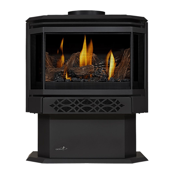
Haliburton™
(MUST use title from Price Book)
ADD ____ ILLUSTRATED
ADD PRODUCT IMAGE
FOR INDOOR USE ONLY
NUMBER LABEL HERE
IF SEPARATE MANUALS, ADD "PLACE
ENGLISH
FRENCH PG. 55
(GDS28-1 illustrated)
W415-2339 / C / 02.08.21
Advertisement
Table of Contents
Troubleshooting

Related Manuals for Napoleon Haliburton GDS28-1NSB


Summary of Contents for Napoleon Haliburton GDS28-1NSB
- Page 1 INTERTEK BARCODE LABEL ON THE OWNER’S MANUAL” LOGO Wolf Steel Ltd., 24 Napoleon Rd., Barrie, ON, L4M 0G8 Canada / 103 Miller Drive, Crittenden, Kentucky, USA, 41030 Phone 1 (866) 820-8686 • www.napoleon.com • hearth@napoleon.com $10.00 W415-2339 / C / 02.08.21...
- Page 2 safety information WARNING DANGER This appliance is hot when operated and can cause severe burns if contacted. Any changes or alterations to this appliance or its controls can be dangerous and is prohibited. HOT GLASS WILL CAUSE • Do not operate appliance before reading and BURNS.
- Page 3 safety information WARNING • Do not use a blower insert, heat exchanger insert or other accessory not approved for use with this appliance. • This appliance must not be connected to a chimney fl ue pipe serving a separate solid fuel burning appliance.
-
Page 4: Table Of Contents
table of contents finishing general information safety screen installation and removal rates and effi ciencies general instructions door closing and opening rating plate information log placement mobile home installation (model glowing embers GDS28) charcoal embers dimensions logo placement venting control access cover removal / typical vent installation installation special vent installations... -
Page 5: General Information
standard checklist Installer, please fi ll out the following information: Customer: _____________________________________________________________________ Address: _____________________________________________________________________ Date of Installation: _____________________________________________________________________ Location of Appliance: _____________________________________________________________________ Installer: _____________________________________________________________________ Dealer/Distributor Contact Number: _____________________________________________________________________ Serial #: _____________________________________________________________________ Model: Natural Gas: GDS28-1NSB Propane: GDS28-1PSB GS28-1N GS28-1P GDS28-1NE GDS28-1PE GS28-1NE GS28-1PE... -
Page 6: General Instructions
general information general instructions WARNING • Always light the pilot, whether for the fi rst time or if the gas supply has run out, with the glass door opened or removed. • Provide adequate clearance for servicing and operating the appliance. •... -
Page 7: Rating Plate Information
Recessed depth X” Profondeur d’encastré une face X” L’appareil doit être ventilé à l’aide de l’ensemble d’évacuation propre à Napoleon. Référez au *** Mantel X” from appliance opening *** Tablette X” de l’ouverture de l’appareil manuel d’installation pour les spécifications d’évacuation. Il est nécessaire de bien réinstaller et... -
Page 8: Dimensions
general information dimensions W415-2339 / C / 02.08.21... -
Page 9: Venting
2.0 venting WARNING • Risk of fi re. Maintain specifi ed air space clearances to vent pipe and appliance. • The vent system must be supported every 3’(0.9m) for both vertical and horizontal runs. Use support ring assembly W010- 0067 or equivalent non-combustible strapping to maintain the minimum clearance to combustibles for both vertical and horizontal runs. -
Page 10: Typical Vent Installation
venting These vent kits allow for either horizontal or vertical venting of the appliance. The maximum allowable horizontal run is 20 feet (6.1m). The maximum allowable vertical vent length is 40 feet (12.2m). The maximum number of vent connections is two horizontally or three vertically (excluding the appliance and the air terminal connections) when using fl... -
Page 11: Special Vent Installations
venting special vent installations 2.2.1 periscope termination Use the periscope kit to locate the air termination above grade. The periscope must be installed so that when fi nal grading is completed, the bottom air slot is located a minimum 12” (305mm) above grade. The maximum allowable vent length (including both rise and run) is 10’... -
Page 12: Vent Terminal Clearances
venting vent terminal clearances Covered balcony applications ††* = 3 feet = 2 x ACTUAL (0.9m) (4.6m) note: INSTALLATIONS Wall terminals are for illustration purposes only. Size and shapes may vary. CANADA U.S.A. 12” (30.5cm) 12” (30.5cm) Clearance above grade, veranda porch, deck or balcony. 12”... -
Page 13: Vent Fl Ow Charts
venting vent fl ow charts Top Exit Horizontal Termination Vertical Termination Vertical rise is equal Vertical rise is equal Vertical rise is less Vertical rise is less to or greater than the to or greater than the than horizontal run than horizontal run horizontal run horizontal run... -
Page 14: Horizontal Termination
venting horizontal termination ) < (V Simple venting confi guration (only one 90° elbow) See graph to determine the required vertical rise V for the required horizontal run H 40 (12.2) 39 (11.9) REQUIRED 30 (9.1) VERTICAL RISE IN FEET 20 (6.1) (METERS)V 10 (3.1) - Page 15 venting ) > (V Simple venting configuration (only one 90° elbow) See graph to determine the required vertical rise V the required horizontal run H 150 (3810) 147 (3733.8) REQUIRED VERTICAL RISE IN INCHES 100 (2540) (MILLIMETERS) V 57 (1447.8) 50 (1270) 29 (736.6) 20 (6.1)
-
Page 16: Top Exit Vertical Termination
venting top exit vertical termination ) < (V Simple venting configurations. See graph to determine the required vertical rise V for the required horizontal run H 40 (12.2) 30 (9.1) REQUIRED VERTICAL RISE IN FEET 20 (6.1) (METERS) V 10 (3.1) 3 (0.9) (1.5) (3.1) - Page 17 venting ) > (V Simple venting configurations. See graph to determine the required vertical rise V for the required horizontal run H 20 (6.1) 19 (5.8) REQUIRED VERTICAL RISE IN FEET 10 (3.1) (METERS) V 3 (0.9) (7.6) (9.1) (1.5) (3.1) (4.6) (6.1)
-
Page 18: Vertical Through Existing Chimney
venting vertical through existing chimney WARNING • Risk of fi re. • Co-axial to co-linear venting confi gurations must only be used in a non-combustible chimney or enclosure. Installation in a combustible enclosure could result in a fi re. This appliance is designed to be attached to a 3” (76.2mm) co-linear aluminum fl ex vent system running the full length of a masonry chimney. -
Page 19: Installation
3.0 installation WARNING • Ensure to unpack all loose materials from inside the fi rebox prior to connecting the gas and electrical supply If your appliance is supplied with a remote, ensure the remote receiver is in the “OFF” position prior to connecting the gas and electrical supply to the appliance. -
Page 20: Horizontal Installation
installation 3.1.1 horizontal installation WARNING • The fi restop assembly must be installed with the vent shield to the top. • Terminals must not be recessed into a wall or siding more than the depth of the return fl ange of the mounting plate. -
Page 21: Vertical Installation
installation 3.1.2 vertical installation This application occurs when venting through a roof. Installation kits for various roof pitches are available from your authorized dealer / distributor. See the “accessories” section to order specifi c kits required. A. Determine the air terminal location, cut and frame a square opening, as illustrated, in the ceiling and the roof to provide the minimum 1"... -
Page 22: Vertical Air Terminal Installation
installation 3.1.4 vertical air terminal installation WARNING • Maintain a minimum 2” (51mm) space between the air inlet base and the storm collar. note: Fastening hardware provided with appropriate roof terminal and liner kits. Fasten the roof support to the roof using 6 screws. The roof support is optional. -
Page 23: Appliance Vent Connection
installation appliance vent connection Attach the adjustable pipe to the last section of rigid pipe. Secure with screws and seal. #8 X 1/2” Self Drilling INSERT Install the inner fl ex pipe to the appliance. Secure with a minimum of Screws three screws and fl... -
Page 24: Installing Natural Vent
installation 3.3.3 installing natural vent Follow the instructions of the natural vent manufacturer for chimney installation. Remove and discard the two combustion air cover plates and gaskets located on the rear panel of the appliance. Replace the four screws per side to secure the rear panel to the appliance. -
Page 25: Adding Vent Sections
installation 3.3.5 adding vent sections Add chimney sections, according to the manufacturer’s installation instructions. If the chimney system passes through an attic space, a rafter radiation shield or attic insulation shield is required. The chimney must extend at least 3ft (0.9m) above its point of contact with the roof and at least 2ft (0.6m) higher than any wall, roof or building within 10ft (3.1m). -
Page 26: Gas Installation
4.0 gas installation WARNING • Risk of fi re, explosion, or asphyxiation. Ensure there are no ignition sources such as sparks or open fl ames. • Support gas control when attaching gas supply pipe to prevent damaging gas line. • Always light the pilot whether for the fi... -
Page 27: Finishing
6.0 fi nishing WARNING • Risk of fi re! • Never obstruct the front opening of the appliance. • The front of the appliance must be fi nished with any non-combustible materials such as brick, marble, granite, etc., provided that these materials do not go below the specifi ed dimension, as illustrated. •... -
Page 28: Door Closing And Opening
fi nishing door closing and opening WARNING • Glass may be hot. Do not touch glass until cooled. • If equipped with door latches that are part of a safety system, they must be properly engaged. Do not operate the appliance with latches disengaged. •... -
Page 29: Log Placement
fi nishing log placement WARNING • Failure to position the logs in accordance with these diagrams or failure to use only logs specifi cally approved with this appliance may result in property damage or personal injury. • Logs must be placed in their exact location in the appliance. Do not modify the proper log positions, since appliance may not function properly and delayed ignition may occur. -
Page 30: Glowing Embers
fi nishing glowing embers WARNING • Completely blocking the burner ports can cause an incorrect fl ame pattern, carbon deposits and delayed ignition. Tear the embers into pieces and loosely layer above the burner ports covering the burner area. Care should be taken to shred the embers into thin, small irregular pieces as only the exposed edges of the fi... -
Page 31: Operating Instructions
7.0 operating instructions operation (electronic) operating/lighting instructions The on-off switch is located on the back of the appliance at the top left corner on models GDS28 and GS28. When lit for the fi rst time, the appliance will emit a slight odour for a few hours. This is a normal temporary condi- tion caused by the "burn-in"... -
Page 32: Wiring Diagram (Electronic)
8.0 wiring diagram (electronic) operation (electronic) WARNING • Do not wire 110 volts to the valve or wall switch. note: This appliance comes equipped with a battery back-up. If this back-up is used, install 4 ‘AA’ batteries (not supplied) into the holder and connect to the wire harness. Connect the battery holder to the wire harness before using the appliance. -
Page 33: Operation (Electronic)
9.0 operation (electronic) operation (electronic) WARNING • If you do not follow these instructions exactly, a fi re or explosion may result causing property damage, personal injury, or loss of life. • If applicable, always light the pilot whether for the fi rst time or if the gas supply has run out with the glass door opened or removed. -
Page 34: Pilot-On-Demand
In order to start your pilot, turning the main burner on with the switch, remote or thermostat and then turning it off will reactivate the continuous pilot mode and reset the seven day timer. For further information, refer to www.napoleon.com/pilotondemand. W415-2339 / C / 02.08.21... -
Page 35: Operation (Millivolt)
10.0 operation (millivolt) operation (millivolt) WARNING • If you do not follow these instructions exactly, a fi re or explosion may result causing property damage, personal injury, or loss of life. • If applicable, always light the pilot whether for the fi rst time or if the gas supply has run out with the glass door opened or removed. -
Page 36: Adjustment
11.0 adjustment 11.1 pilot burner adjustment Adjust the pilot screw to provide properly sized fl ame. Turn in a clockwise direction to reduce the gas fl ow. PILOT ELECTRODE Check Pressure Readings: BURNER 3/8” - 1/2” Inlet pressure can be checked by turning screw (A) counter- (9.5mm - 12.7mm) clockwise 2 or 3 turns and then placing pressure gauge tubing ELECTRONIC... -
Page 37: Venturi Adjustment
11.2 venturi adjustment This appliance has an air shutter that has been factory set open according to the chart below: VENTURI Regardless of venturi orientation, closing the air shutter will cause a more BURNER yellow flame, but can lead to carbonization. Opening the air shutter will cause a more blue flame, but can cause flame lifting from the burner ports. -
Page 38: Maintenance
12.0 maintenance WARNING • Turn off the gas and electrical power before servicing the appliance. • Appliance may be hot. Do not service until appliance has cooled. • Do not use abrasive cleaners on glass. • Do not paint the pilot assembly. This appliance and its venting system should be inspected before use and at least annually by a qualifi... -
Page 39: Annual Maintenance
maintenance 12.1 annual maintenance WARNING • Annual maintenance should be performed by a qualifi ed service technician • The fi rebox becomes very hot during operation. Let the appliance cool completely or wear heat resistant gloves before conducting service. • Never vacuum hot embers. -
Page 40: Blower Replacement
maintenance 12.3 blower replacement Blower replacement may be done through either the fi rebox or from the rear of the appliance. Using the rear panel is recommended. BLOWER INSTALLATION THROUGH THE REAR PANEL : FOR MODEL GDS28 • Turn off the electrical power and the gas supply to the appliance. white •... -
Page 41: Replacement Parts
13.0 replacement parts WARNING • Failure to position the parts in accordance with this manual or failure to use only parts specifi cally approved with this appliance may result in property damage or personal injury. Contact your dealer for questions concerning prices and policies on replacement parts. Normally, all parts can be ordered through your Authorized dealer / distributor. -
Page 42: Overview
replacement parts W415-2339 / C / 02.08.21... -
Page 43: Millivolt Valve Train Assembly
replacement parts W415-2339 / C / 02.08.21... -
Page 44: Electronic Valve Train Assembly
replacement parts W415-2339 / C / 02.08.21... -
Page 45: Accessories
14.0 accessories accessories W415-2339 / C / 02.08.21... -
Page 46: Troubleshooting (Millivolt)
troubleshooting (millivolt) 15.0 troubleshooting (millivolt) WARNING • Always light the pilot whether for the fi rst time or if the gas supply has run out, with the glass door open or removed. • Turn off gas and electrical power before servicing the appliance. •... - Page 47 troubleshooting (millivolt) symptom problem test solution Exhaust fumes smelled Appliance is spilling. Check door seal. in room, headaches. (This is not applicable in outdoor Check for exhaust damage. appliances) Check that venting is installed correctly. Room is in negative pressure; increase fresh air supply. Exhaust fumes smelled Appliance is spilling.
- Page 48 troubleshooting (millivolt) symptom problem test solution Door Sticking Dirt / dust adheres to the hinges; Lift door from its hinges. Lubricate with high temp dry is heated and burns causing graphite only. Replace. sticking. NOTE: Due to the high temperatures that the hinges experience, wet lubricants such as oil and WD40 will cause the hinge to seize and are therefore not suitable.
-
Page 49: Troubleshooting (Electronic)
16.0 troubleshooting (electronic) troubleshooting (electronic) WARNING • Always light the pilot whether for the fi rst time or if the gas supply has run out, with the glass door open or removed. • Turn off gas and electrical power before servicing the appliance. •... - Page 50 troubleshooting (electronic) symptom problem test solution Pilot will not light. Makes Wiring: short, loose, or damaged Verify the thermocouple/sensor is clean and the wiring is undamaged. Verify the interrupter block is not damaged or too tight. Verify noise with no spark at connections connections from pilot assembly are tight;...
- Page 51 troubleshooting (electronic) symptom problem test solution Lights or blower Control module switch in Verify ON/OFF switch is in the “I” position which denotes on. won’t function (if wrong position. equipped). COM switch is unplugged. Verify “COM” switch is plugged into the front of the control module.
-
Page 52: Warranty
Napoleon neither assumes, nor authorizes any third party to assume, on its behalf, any other liabilities with respect to the sale of this product. Napoleon will not be responsible for: over- fi ring, downdrafts, spillage caused by environmental conditions such as rooftops, buildings, nearby trees, hills, mountains, inadequate vents or ventilation, excessive venting confi... -
Page 53: Service History
18.0 service history service history W415-2339 / C / 02.08.21... - Page 54 NAPOLEON CELEBRATING OVER 40 YEARS OF HOME COMFORT PRODUCTS 7200, Route Transcanadienne, Montréal, Québec H4T 1A3 24 Napoleon Road, Barrie, Ontario, Canada L4M 0G8 Scan this QR code for more information or visit our website at: Scan fo for more...