Napoleon Haliburton GDS28N Installation And Operation Manual
Hide thumbs
Also See for Haliburton GDS28N:
- Installation and operating instructions manual (104 pages) ,
- Installation and operation instructions manual (24 pages) ,
- Installation and operating instructions manual (96 pages)
Table of Contents
Advertisement
Available languages
Available languages
NATURAL GAS MODELS:
PROPANE GAS MODELS:
SAFETY INFORMATION
WARNING
!
FIRE OR EXPLOSION HAZARD
Failure to follow safety warnings exactly
could result in serious injury, death, or
property damage.
- Do not store or use gasoline or other
fl ammable vapors and liquids in the vicinity of
this or any other appliance.
- WHAT TO DO IF YOU SMELL GAS:
•
Do not try to light any appliance.
•
Do not touch any electrical switch; do not
use any phone in your building.
•
Immediately call your gas supplier from a
neighbour's phone. Follow the gas
supplier's instructions.
•
If you cannot reach your gas supplier, call
the fi re department.
- Installation and service must be
performed by a qualifi ed installer, service
agency, or the supplier.
This appliance may be installed in an aftermarket,
permanently located, manufactured home (USA
only) or mobile home, where not prohibited by
local codes.
This appliance is only for use with the type of gas
indicated on the rating plate. This appliance is
not convertible for use with other gases, unless
a certifi ed kit is used.
INSTALLER:
Leave this manual with the appliance
CONSUMER:
Retain this manual for future reference
Wolf Steel Ltd., 24 Napoleon Rd., Barrie, ON, L4M 0G8 Canada / 103 Miller Drive, Crittenden, Kentucky, USA, 41030
$10.00
GDS28N / GS28N
ADD PRODUCT CODE HERE (TRADE GOTHIC LT STD FONT)
GDS28P / GS28P
Phone 1 (866) 820-8686 • www.napoleon.com • hearth@napoleon.com
INSTALLATION AND
ADD MANUAL TITLE
OPERATION MANUAL
Model GS28 is made up of Model GDS28 and
Natural Vent Adapter Kit GS-150KT
CERTIFIED TO THE CANADIAN AND AMERICAN NATIONAL STANDARDS:
CSA 2.22 AND ANSI Z21.50 FOR VENTED DECORATIVE GAS APPLIANCES
IF INSTALLATION + OPERATION, ADD SERIAL
CSA /
INTERTEK
BARCODE LABEL ON THE OWNER'S MANUAL"
LOGO
Product Name / Code
Haliburton™
(MUST use title from Price Book)
ADD ____ ILLUSTRATED
ADD PRODUCT IMAGE
FOR INDOOR USE ONLY
NUMBER LABEL HERE
IF SEPARATE MANUALS, ADD "PLACE
ENGLISH
FRENCH PG. 45
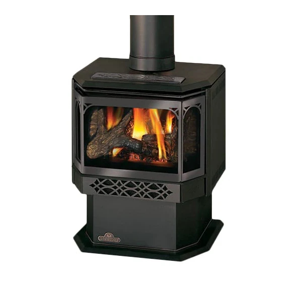
(GDS28 illustrated)
W415-1426 / D / 05.22.19
Advertisement
Chapters
Table of Contents

Related Manuals for Napoleon Haliburton GDS28N


Summary of Contents for Napoleon Haliburton GDS28N
- Page 1 INTERTEK BARCODE LABEL ON THE OWNER’S MANUAL” LOGO Wolf Steel Ltd., 24 Napoleon Rd., Barrie, ON, L4M 0G8 Canada / 103 Miller Drive, Crittenden, Kentucky, USA, 41030 Phone 1 (866) 820-8686 • www.napoleon.com • hearth@napoleon.com $10.00 W415-1426 / D / 05.22.19...
- Page 2 safety information WARNING • This appliance is hot when operated and DANGER can cause severe burns if contacted. • Any changes or alterations to this appliance or its controls can be dangerous and is prohibited. HOT GLASS WILL CAUSE • Do not operate appliance before reading and BURNS.
- Page 3 safety information WARNING • Do not use a blower insert, heat exchanger insert or other accessory not approved for use with this appliance. • This appliance must not be connected to a chimney fl ue pipe serving a separate solid fuel burning appliance.
-
Page 4: Table Of Contents
table of contents gas installation general information optional wall switch / remote rates and effi ciencies finishing general instructions safety screen installation and removal 26 rating plate information door closing and opening dimensions log placement mobile home installation (model glowing embers GDS28) charcoal embers venting... -
Page 5: General Information
standard checklist Installer, please fi ll out the following information: Customer: _____________________________________________________________________ Address: _____________________________________________________________________ Date of Installation: _____________________________________________________________________ Location of Appliance: _____________________________________________________________________ Installer: _____________________________________________________________________ Dealer/Distributor Contact Number: _____________________________________________________________________ Serial #: _____________________________________________________________________ Model: Natural Gas: Propane: GDS28-1NSB GDS28-1PSB GS28N GS28P 1.0 general information When the appliance is installed at elevations above 4,500 ft (1372m), and in the absence of specifi... -
Page 6: General Instructions
general information general instructions WARNING • Always light the pilot, whether for the fi rst time or if the gas supply has run out, with the glass door opened or removed. • Provide adequate clearance for servicing and operating the appliance. •... -
Page 7: Rating Plate Information
Les longeurs horizontales minimale et maximale sont 25 pounces Les longeurs horiz eurs ho L’appareil doit être ventilé à l’aide de l’ensemble d’évacuation propre à Napoleon. Référez au et 20 pieds respectivement. et 20 pieds manuel d’installation pour les spécifications d’évacuation. Il est nécessaire de bien réinstaller et This appliance must be installed using an adapter kit GS-150KT. -
Page 8: Venting
2.0 venting WARNING • Risk of fi re. Maintain specifi ed air space clearances to vent pipe and appliance. • The vent system must be supported every 3’(0.9m) for both vertical and horizontal runs. Use support ring assembly W010- 0067 or equivalent non-combustible strapping to maintain the minimum clearance to combustibles for both vertical and horizontal runs. -
Page 9: Typical Vent Installation
venting These vent kits allow for either horizontal or vertical venting of the appliance. The maximum allowable horizontal run is 20 feet (6.1m). The maximum allowable vertical vent length is 40 feet (12.2m). The maximum number of vent connections is two horizontally or three vertically (excluding the appliance and the air terminal connections) when using fl... -
Page 10: Special Vent Installations
venting special vent installations 2.2.1 periscope termination Use the periscope kit to locate the air termination above grade. The periscope must be installed so that when fi nal grading is completed, the bottom air slot is located a minimum 12” (305mm) above grade. The maximum allowable vent length (including both rise and run) is 10’... -
Page 11: Vent Terminal Clearances
venting vent terminal clearances Covered balcony applications ††* = 3 feet = 2 x ACTUAL (0.9m) (4.6m) note: INSTALLATIONS Wall terminals are for illustration purposes only. Size and shapes may vary. CANADA U.S.A. 12” (30.5cm) 12” (30.5cm) Clearance above grade, veranda porch, deck or balcony. 12”... -
Page 12: Vent Fl Ow Charts
venting vent fl ow charts Top Exit Horizontal Termination Vertical Termination Vertical rise is equal Vertical rise is equal Vertical rise is less Vertical rise is less to or greater than the to or greater than the than horizontal run than horizontal run horizontal run horizontal run... -
Page 13: Horizontal Termination
venting horizontal termination ) < (V Simple venting confi guration (only one 90° elbow) See graph to determine the required vertical rise V for the required horizontal run H 40 (12.2) 39 (11.9) REQUIRED 30 (9.1) VERTICAL RISE IN FEET 20 (6.1) (METERS)V 10 (3.1) - Page 14 venting ) > (V Simple venting configuration (only one 90° elbow) See graph to determine the required vertical rise V the required horizontal run H 150 (3810) 147 (3733.8) REQUIRED VERTICAL RISE IN INCHES 100 (2540) (MILLIMETERS) V 57 (1447.8) 50 (1270) 29 (736.6) 20 (6.1)
-
Page 15: Top Exit Vertical Termination
venting top exit vertical termination ) < (V Simple venting configurations. See graph to determine the required vertical rise V for the required horizontal run H 40 (12.2) 30 (9.1) REQUIRED VERTICAL RISE IN FEET 20 (6.1) (METERS) V 10 (3.1) 3 (0.9) (1.5) (3.1) - Page 16 venting ) > (V Simple venting configurations. See graph to determine the required vertical rise V for the required horizontal run H 20 (6.1) 19 (5.8) REQUIRED VERTICAL RISE IN FEET 10 (3.1) (METERS) V 3 (0.9) (7.6) (9.1) (1.5) (3.1) (4.6) (6.1)
-
Page 17: Vertical Through Existing Chimney
venting vertical through existing chimney WARNING • Risk of fi re. • Co-axial to co-linear venting confi gurations must only be used in a non-combustible chimney or enclosure. Installation in a combustible enclosure could result in a fi re. This appliance is designed to be attached to a 3” (76.2mm) co-linear aluminum fl ex vent system running the full length of a masonry chimney. -
Page 18: Installation
3.0 installation WARNING • Ensure to unpack all loose materials from inside the fi rebox prior to connecting the gas and electrical supply • If your appliance is supplied with a remote, ensure the remote receiver is in the “OFF” position prior to connecting the gas and electrical supply to the appliance. -
Page 19: Wall And Ceiling Protection
installation 3.1.1 horizontal installation WARNING • The fi restop assembly must be installed with the vent shield to the top. • Terminals must not be recessed into a wall or siding more than the depth of the return fl ange of the mounting plate. -
Page 20: Vertical Installation
installation 3.1.2 vertical installation This application occurs when venting through a roof. Installation kits for various roof pitches are available from your authorized dealer / distributor. See the “accessories” section to order specifi c kits required. A. Determine the air terminal location, cut and frame a square opening, as illustrated, in the ceiling and the roof to provide the minimum 1"... -
Page 21: Vertical Air Terminal Installation
installation 3.1.4 vertical air terminal installation WARNING • Maintain a minimum 2” (51mm) space between the air inlet base and the storm collar. note: Fastening hardware provided with appropriate roof terminal and liner kits. Fasten the roof support to the roof using 6 screws. The roof support is optional. -
Page 22: Appliance Vent Connection
installation appliance vent connection Attach the adjustable pipe to the last section of rigid pipe. Secure with screws and seal. #8 X 1/2” Self Drilling Install the inner fl ex pipe to the appliance. Secure with a minimum of Screws INSERT three screws and fl... -
Page 23: Installing Natural Vent
installation 3.3.2 installing natural vent Follow the instructions of the natural vent manufacturer for chimney installation. Remove and discard the two combustion air cover plates and gaskets located on the rear panel of the appliance. Replace the four screws per side to secure the rear panel to the appliance. -
Page 24: Adding Vent Sections
installation 3.3.5 adding vent sections Add chimney sections, according to the manufacturer’s installation instructions. If the chimney system passes through an attic space, a rafter radiation shield or attic insulation shield is required. The chimney must extend at least 3ft (0.9m) above its point of contact with the roof and at least 2ft (0.6m) higher than any wall, roof or building within 10ft (3.1m). -
Page 25: Optional Wall Switch / Remote
4.0 gas installation WARNING • Risk of fi re, explosion, or asphyxiation. Ensure there are no ignition sources such as sparks or open fl ames. • Support gas control when attaching gas supply pipe to prevent damaging gas line. • Always light the pilot whether for the fi... -
Page 26: Safety Screen Installation And Removal
6.0 fi nishing WARNING • Risk of fi re! • Never obstruct the front opening of the appliance. • The front of the appliance must be fi nished with any non-combustible materials such as brick, marble, granite, etc., provided that these materials do not go below the specifi ed dimension, as illustrated. •... -
Page 27: Door Closing And Opening
fi nishing door closing and opening WARNING • Glass may be hot. Do not touch glass until cooled. • If equipped with door latches that are part of a safety system, they must be properly engaged. Do not operate the appliance with latches disengaged. •... -
Page 28: Log Placement
fi nishing log placement WARNING • Failure to position the logs in accordance with these diagrams or failure to use only logs specifi cally approved with this appliance may result in property damage or personal injury. • Logs must be placed in their exact location in the appliance. Do not modify the proper log positions, since appliance may not function properly and delayed ignition may occur. -
Page 29: Glowing Embers
fi nishing glowing embers WARNING • Completely blocking the burner ports can cause an incorrect fl ame pattern, carbon deposits and delayed ignition. Tear the embers into pieces and loosely layer above the burner ports covering the burner area. Care should be taken to shred the embers into thin, small irregular pieces as only the exposed edges of the fi... - Page 30 7.0 operation WARNING • If you do not follow these instructions exactly, a fi re or explosion may result causing property damage, personal injury, or loss of life. • Always light the pilot, whether for the fi rst time or if the gas supply has run out, with the glass door opened or removed.
-
Page 31: Operating/Lighting Instructions
operation operating/lighting instructions The on-off switch is located on the back of the appliance at the top left corner on models GDS28 and GS28. When lit for the fi rst time, the appliance will emit a slight odour for a few hours. This is a normal temporary condi- tion caused by the "burn-in"... -
Page 32: Pilot Burner Adjustment
8.0 adjustment pilot burner adjustment Adjust the pilot screw to provide properly sized fl ame. Turn in a clockwise direction to reduce the gas fl ow. Check Pressure Readings: Inlet pressure can be checked by turning screw (A) counter- clockwise 2 or 3 turns and then placing pressure gauge tubing over the test point. - Page 33 9.0 maintenance WARNING • Turn off the gas and electrical power before servicing the appliance. • Appliance may be hot. Do not service until appliance has cooled. • Do not use abrasive cleaners on glass. • Do not paint the pilot assembly. This appliance and its venting system should be inspected before use and at least annually by a qualifi...
-
Page 34: Annual Maintenance
maintenance annual maintenance WARNING • Annual maintenance should be performed by a qualifi ed service technician • The fi rebox becomes very hot during operation. Let the appliance cool completely or wear heat resistant gloves before conducting service. • Never vacuum hot embers. •... -
Page 35: Blower Replacement
maintenance blower replacement Blower replacement may be done through either the fi rebox or from the rear of the appliance. Using the rear panel is recommended. BLOWER INSTALLATION THROUGH THE REAR PANEL : FOR MODEL GDS28 white • Turn off the electrical power and the gas supply to the appliance. THERMAL •... -
Page 36: Replacement Parts
10.0 replacement parts WARNING • Failure to position the parts in accordance with this manual or failure to use only parts specifi cally approved with this appliance may result in property damage or personal injury. Contact your dealer for questions concerning prices and policies on replacement parts. Normally, all parts can be ordered through your Authorized dealer / distributor. -
Page 37: Overview
replacement parts W415-1426 / D / 05.22.19... -
Page 38: Valve Train Assembly
replacement parts W415-1426 / D / 05.22.19... - Page 39 accessories 11.0 accessories W415-1426 / D / 05.22.19...
- Page 40 troubleshooting 12.0 troubleshooting WARNING • Always light the pilot whether for the fi rst time or if the gas supply has run out, with the glass door open or removed. • Turn off gas and electrical power before servicing the appliance. •...
- Page 41 troubleshooting symptom problem test solution Exhaust fumes smelled Appliance is spilling. Check door seal. in room, headaches. (This is not applicable in outdoor Check for exhaust damage. appliances) Check that venting is installed correctly. Room is in negative pressure; increase fresh air supply. Pilot will not light.
- Page 42 troubleshooting symptom problem test solution Door Sticking Dirt / dust adheres to the hinges; Lift door from its hinges. Lubricate with high temp dry is heated and burns causing graphite only. Replace. sticking. NOTE: Due to the high temperatures that the hinges experience, wet lubricants such as oil and WD40 will cause the hinge to seize and are therefore not suitable.
- Page 43 Napoleon neither assumes, nor authorizes any third party to assume, on its behalf, any other liabilities with respect to the sale of this product. Napoleon will not be responsible for: over- fi ring, downdrafts, spillage caused by environmental conditions such as rooftops, buildings, nearby trees, hills, mountains, inadequate vents or ventilation, excessive venting confi...
- Page 44 NAPOLEON CELEBRATING OVER 40 YEARS OF HOME COMFORT PRODUCTS 7200, Route Transcanadienne, Montréal, Québec H4T 1A3 24 Napoleon Road, Barrie, Ontario, Canada L4M 0G8 214 Bayview Drive, Barrie, Ontario, Canada L4N 4Y8 Scan this QR code for more information or visit our website at:...
- Page 45 IF SEPARATE MANUALS, ADD “PLACE LOGO BARCODE LABEL ON THE OWNER’S MANUAL” Wolf Steel Ltd., 24 Napoleon Rd., Barrie, ON, L4M 0G8 Canada / 103 Miller Drive, Crittenden, Kentucky, USA, 41030 Téléphone 1(866)820-8686 • www.napoleon.com • hearth@napoleon.com $10.00 W415-1426 / D / 05.22.19...
- Page 46 consignes de sécurité AVERTISSEMENT • Cet appareil est chaud lorsqu’il AVERTISSEMENT fonctionne et peut causer de graves brûlures en cas de contact. • Toute modifi cation apportée à cet appareil ou aux contrôles peut être LA VITRE CHAUDE CAUSERA dangereux et est interdit. DES BRÛLURES.
- Page 47 consignes de sécurité AVERTISSEMENT • N’utilisez pas une souffl erie intégrée, un échangeur de chaleur intégré ni un autre accessoire non approuvé pour cet appareil. • Cet appareil ne doit pas être raccordé au conduit d’une cheminée desservant un autre appareil de chauffage à...
- Page 48 table des matières information générales interrupteur mural / télécommande taux et effi cacités optionnel instructions générales finitions information sur la plaque installation / enlèvement de l'écran de d’homologation protection dimensions ouverture et fermeture de la porte installation dans une maison mobile - disposition des bûches modèle GDS28 braises incandescentes...
-
Page 49: Information Générales
liste de vérifi cation Installateur, veuillez rempli les informations suivants: Client: _____________________________________________________________________ Addresse: _____________________________________________________________________ Date d'installation: _____________________________________________________________________ Location de l'appareil: _____________________________________________________________________ Installateur: _____________________________________________________________________ Numéro de contact du détaillant / distributeur: _____________________________________________________________________ No. de série: _____________________________________________________________________ Modèle: Gaz naturel: Propane: GDS28N GDS28P GS28N GS28P... -
Page 50: Instructions Générales
information générales instructions générales AVERTISSEMENT • Allumez toujours la veilleuse, que ce soit pour la première fois ou lorsque l’approvisionnement en gaz est épuisé, avec la porte vitrée ouverte ou retirée. • Prévoyez un accès suffi sant pour entretenir et opérer l’appareil. •... -
Page 51: Information Sur La Plaque
Les longeurs horizontales minimale et maximale sont 25 pounces Les longeurs horizontales Les longeurs horizont L’appareil doit être ventilé à l’aide de l’ensemble d’évacuation propre à Napoleon. Référez au et 20 pieds respectivement. et 20 pieds respectivem et 20 pieds respective manuel d’installation pour les spécifications d’évacuation. -
Page 52: Évacuation
2.0 évacuation évacuation AVERTISSEMENT • Risque d’incendie. Conservez les dégagements nécessaires au conduit d’évent et à l’appareil. • Les courses horizontales et verticales du système doivent être supportées à tous les 3 pi (0,9m). Utilisez l’ensemble de support mural Wolf Steel W010-0067 ou des attaches incombustibles équivalents afi n de maintenir le dégagement aux matériaux combustibles pour les courses verticales et horizontales. - Page 53 évacuation Lorsque vous utilisez les composants d'évacuation Wolf Steel, n'utilisez que des composants d'évacuation Wolf Steel conjointement avec les ensembles de terminaison suivants: ensemble de terminaison murale GD-175 (7/12" de conduits inclus), ou ensemble de terminaison pour toit de pente 1/12 à 7/12 GD-110, ensemble de termi- naison pour toit de pente 8/12 à...
-
Page 54: Installations Typiques D'évents
évacuation installations typiques d'évents 16" (40.6cm) Minimum 34" (86.4cm) Maximum 29" (73.7cm) Minimum 55 3/4" (141.6cm) 40 ft (12m) Minimum Maximum Plus la Pente * 3 ft (1m) Minimum * Voir la section « ÉVACUATION » installations particulières d'évents 2.2.1 ensemble périscopique Utilisez l’ensemble périscopique afi... -
Page 55: Emplacements Et Dégagements
évacuation emplacements et dégagements minimaux de la terminaison Applications pour balcon couvert ††* = 3 feet = 2 x ACTUAL (0.9m) (4.6m) note: INSTALLATIONS Les terminaux du mur sont à des fi ns d’illustration seulement. La taille et les formes peuvent varier. CANADA É.-U. -
Page 56: Charte D'application Des Évacuations
évacuation charte d'application des évacuations Évacuation sur le dessus Terminaison horizontale Terminaison verticale La course verticale est La course verticale La course verticale La course verticale plus grande ou égale à est plus petite que la est plus grande ou est plus petite que la la course horizontale course horizontale... -
Page 57: Évacuation Sur Le Dessus - Terminaison
évacuation évacuation sur le dessus - terminaison horizontale ) < (V Confi guration d’évacuation simple Consultez le graphique pour déterminer la course verticale nécessaire V par rapport à la (un coude de 90° seulement). course horizontale requise H 40 (12,2) 39 (11,9) COURSE 30 (9,1) - Page 58 évacuation ) > (V Consultez le graphique pour déterminer la course verticale Configuration d'évacuation simple (un coude de 90° nécessaire V par rapport à la course horizontale requise H seulement). 150 (3810) 147 (3733,8) COURSE VERTICALE 100 (2540) REQUISE EN POUCES (MILLIMÈTRES)V 57 (1447,8)
- Page 59 évacuation évacuation sur le dessus - terminaison verticale ) < (V Configuration d'évacuation simple. Consultez le graphique pour déterminer la course verticale nécessaire V par rapport à la course horizontale requise H 40 (12,2) 30 (9,1) COURSE VERTICALE REQUISE EN 20 (6,1) PIEDS (MÈTRES)V...
- Page 60 évacuation ) > (V Configuration d'évacuation simple. Consultez le graphique pour déterminer la course verticale nécessaire V par rapport à la course horizontale requise H 20 (6,1) 19 (5,8) COURSE VERTICALE REQUISE EN 10 (3,1) PIEDS (MÈTRES) V 3 (0,9) (1,5) (3,1) (4,6)
-
Page 61: Terminaison Verticale À Travers Une
évacuation terminaison verticale à travers une cheminée existante AVERTISSEMENT • Risque d’incendie • Les confi gurations d’évacuation coaxiales à colinéaires ne doivent être utilisées que dans une cheminée ou une enceinte de nature incombustible. Une installation dans une enceinte combustible peut causer un incendie. Cet appareil est conçu pour être raccordé... -
Page 62: Installation
installation 3.0 installation AVERTISSEMENT • Avant d’effectuer les branchements pour l’alimentation en gaz et électronique, assurez-vous de retirer toute composante non fi xée à l’intérieur de la chambre de combustion. • Si votre appareil comprend un système de télécommande, assurez-vous que le récepteur est à la position «... -
Page 63: Installation Horizontale
installation 3.1.1 installation horizontale AVERTISSEMENT • L’espaceur coupe-feu doit être installé avec l’écran protecteur orienté vers le haut. • La terminaison ne doit pas être enchâssée dans le mur ou le revêtement extérieur plus que l’épaisseur de la bride de la plaque de montage. PROTECTEUR Cette confi... -
Page 64: Installation Verticale
installation 3.1.2 installation verticale Cette confi guration s’applique lorsque l’évacuation se fait à travers un toit. Des ensembles d’installation pour les différentes pentes de toit sont disponibles chez votre détaillant autorisé. Voir la section « accessoires » dans le manuel du propriétairepour commander l’ensemble spécifi que dont vous avez besoin. -
Page 65: Installation De La Terminaison Verticale
installation 3.1.4 installation de la terminaison verticale AVERTISSEMENT • Conservez un espace minimale de 2 po (51mm) entre la base de la prise d’air et le collet de solin. Matériel de fi xation fourni avec les ensembles de terminal pour toit et raccord appropriées. Fixez le support de toit au toit à... -
Page 66: Raccordement Des Évents À L'appareil
installation raccordement des évents à l'appareil Attachez le tuyau télescopique à la dernière section de conduit rigide. Fixez-le avec des vis et scellez. #8 X 1/2” Fixez-la à l’aide d’au moins trois vis et rondelles lorsque vous autoperceuses INSERT 2” (50.8mm) utilisant une évent de 3”/5”, 4”/7”... -
Page 67: Installation De L'évent De Type « B
installation 3.3.2 installation de l'évent de type « B » Suivez les instructions du fabricant de l'évent de type « B » pour l'installation de la cheminée. Enlevez et jetez les deux plaques couvrant les entrées d'air comburant, ainsi que leur joint d'étanchéité, qui se trouvent sur le panneau arrière de l'appareil. -
Page 68: Ajout De Sections D'évents
installation 3.3.5 ajout de sections d'évents Ajoutez des sections de cheminée, selon les instructions d’installation du fabricant. Si la cheminée devra dépasser par l’espace grenier un écran protecteur de chevrons ou une bouclier d'isolation du grenier est requis. La cheminée doit dépasser le toit d’au moins 3’... -
Page 69: Branchement Du Gaz
4.0 branchement du gaz installation AVERTISSEMENT • Risque d’incendie, d’explosion, ou d’asphyxie. Assurez-vous qu’il n’y ait aucune source d’allumage comme des étincelles ou une fl amme nue. • Soutenez le contrôle du gaz lorsque vous attachez le tuyau pour éviter de plier la conduite de gaz. •... -
Page 70: Finitions
6.0 fi nitions fi nitions AVERTISSEMENT • Risque d’incendie! • N’obstruez jamais l’ouverture sur le devant de l’appareil. • La façade de l’appareil doit être faite de matériaux incombustibles comme de la brique, du marbre, du granite, etc., à condition que ces matériaux ne se trouvent pas en deçà de la dimension spécifi ée tel qu’illustré. Comme alternative, vous pouvez utiliser le panneau de gypse comme fi... -
Page 71: Ouverture Et Fermeture De La Porte
fi nitions ouverture et fermeture de la porte AVERTISSEMENT • La vitre peut être chaude. Ne touchez pas la vitre jusqu’à ce qu’elle ait refroidi. • Les loquets de porte font partie d’un dispositif de sécurité et doivent être adéquatement verrouillés. Ne faites pas fonctionner l’appareil lorsque les loquets sont déverrouillés. -
Page 72: Disposition Des Bûches
fi nitions disposition des bûches AVERTISSEMENT • Omettre de positionner les bûches conformément aux schémas ou omettre d’utiliser uniquement des bûches spécifi quement approuvées pour cet appareil peut causer des dommages matériels ou des blessures corporelles. • Les bûches doivent être placées correctement à l’intérieur de l’appareil. Ne changez pas la position des bûches car l’appareil risque de ne pas fonctionner adéquatement et un retard d’allumage risque de se produire. -
Page 73: Braises Incandescentes
fi nitions braises incandescentes AVERTISSEMENT • Obstruez pas ni fermer les orifi ces du brûleur. Le blocage des orifi ces du brûleur peut créer une fl amme irrégulière, des dépôts de carbone et un retard d’allumage. Déchirez les braises incandescentes en morceaux et placez une couche lâche sur le grillage du brûleur. Les braises devraient être déchirées très soigneusement en petits morceaux minces irréguliers, car seuls les côtés des fi... -
Page 74: Fonctionnement
7.0 fonctionnement fonctionnement AVERTISSEMENT • Si ces instructions ne sont pas suivies à la lettre, un incedie ou une explosion pourraient s'ensuivre, causant des dommages matériels, des blessures corporelles ou des pertes de vie • Allumez toujours la veilleuse, que ce soit pour la première fois ou lorsque l'approvisionnement en gaz est épuisé, avec la porte vitrée ouverte ou retirée. -
Page 75: Instructions D'opération / Allumage
fonctionnement instructions d'opération / allumage L’interrupteur marche/arrêt des modèles GDS28 et GS28 est situé à l’arrière de l'appareil, dans le coin supérieur gauche. Lorsqu’il est allumé pour la première fois, l'appareil dégagera une légère odeur pendant quelques heures. Cela est une condition normale temporaire causée par la cuisson de la peinture et l’évaporation des lubrifi ants internes utilisés dans le processus de fabrication;... -
Page 76: Réglages
8.0 réglages réglages réglage de la veilleuse Ajustez la vis de la veilleuse pour obtenir une fl amme de taille normale. Tournez vers la droite pour réduire l’apport de gaz. Vérifi ez la pression: Pour vérifi er la pression d’arrivée, tournez la vis (A) vers la gauche deux à... -
Page 77: Entretien
9.0 entretien entretien AVERTISSEMENT • Coupez l’alimentation en gaz et l’alimentation électrique avant de procéder à l’entretien de l’appareil. • L’appareil peut être chaud. Attendez qu’il soit refroidi avant d’en faire l’entretien. • N’utilisez pas de produits abrasifs. • Ne peinture pas l’assemblage de la veilleuse. Cet appareil et son système d’évacuation devraient être inspectés avant la première utilisation et au moins une fois l’an par un technicien de service qualifi... -
Page 78: Entretien Annuel
entretien entretien annuel AVERTISSEMENT • Le caisson devient trés chaud lors du fonctionnement. Laissez l’appareil se refroidir complétement ou portez des gants antichaleur avant d’effectuer l’entretien. • Ne jamais aspirer des braises qui sont chaudes. • Ne peinturez pas l’assemblage de la veilleuse. •... -
Page 79: Remplacement De La Souffl Erie
entretien remplacement de la souffl erie SOUFFLERIE Le remplacement de la souffl erie peut être fait depuis la chambre de combustion ou depuis le panneau. Nous vous conseillons cette dernière option. INSTALLATION DEPUIS LE PANNEAU ARRIÈRE : blanc POUR LE MODÈLE GDS28 THERMODISQUE •... -
Page 80: Pièces De Rechange
pièces de rechange 10.0 pièces de rechange AVERTISSEMENT • Omettre de positionner les pièces conformément à ce manuel ou d’utiliser uniquement des pièces spécifi quement approuvées pour cet appareil peut causer des dommages matériels ou des blessures corporelles. Contactez votre détaillant pour les questions concernant les prix et la disponibilité des pièces de remplace- ment. -
Page 81: Vue D'ensemble
pièces de rechange W415-1426 / D / 05.22.19... -
Page 82: Assemblage De La Soupape
pièces de rechange W415-1426 / D / 05.22.19... -
Page 83: Accessoires
pièces de rechange 11.0 accessoires W415-1426 / D / 05.22.19... -
Page 84: Guide De Dépannage
guide de dépannage 12.0 guide de dépannage AVERTISSEMENT • Allumez toujours la veilleuse, que ce soit pour la première fois ou lorsque l’approvisionnement en gaz est épuisé, avec la porte vitrée ouverte ou retirée. • Coupez l’alimentation en gaz et l’alimentation électrique avant de procéder à l’entretien de l’appareil. •... - Page 85 guide de dépannage symptôme problème solutions La veilleuse ne Aucune étincelle au brûleur de la Vérifi ez si la veilleuse peut être allumée avec une allumette. s’allume pas. veilleuse. Vérifi ez si le fi l est raccordé au bouton-poussoir d’ignition. Vérifi...
- Page 86 guide de dépannage SYMPTÔME PROBLÈME SOLUTIONS La porte se coince. La poussiére/saleté adhère aux Enlevez la porte des charnières en la soulevant. Lubrifi ez charnières; elle est chauffée et les charnières avec du graphite. Replacez. brûle, coinçant ainsi la porte. NOTE : Étant donné...
-
Page 87: Garantie
12.0 garantie garantie Les produtits Napoléon sont fabriqués conformément aux normes strictes du Système de Gestion de la Qualité mondialement reconnu ISO 9001 : 2015. Les produits Napoléon sont conçus avec des composants et des matériaux de qualité supérieure, assemblés par des artisans qualifi... - Page 88 À T IO E PR ODUITS CONFORT 7200, Route Transcanadienne, Montréal, Québec H4T 1A3 24 Napoleon Road, Barrie, Ontario, Canada L4M 0G8 214 Bayview Drive, Barrie, Ontario, Canada L4N 4Y8 103 Miller Drive, Crittenden, Kentucky, USA 41030 Téléphone: 1-866-820-8686 napoleon.com...