Table of Contents
Advertisement
Quick Links
Advertisement
Table of Contents

Related Manuals for KTM 790 Duke 2019


Summary of Contents for KTM 790 Duke 2019
- Page 1 OWNER'S MANUAL 2019 790 Duke Art. no. 3213925en...
- Page 3 DEAR KTM CUSTOMER Congratulations on your decision to purchase a KTM motorcycle. You are now the owner of a state-of-the-art DEAR KTM CUSTOMER sports vehicle that will continue giving you pleasure for a long time if you maintain it properly.
- Page 4 Reproduction, even in part, as well as copying of all kinds, is permitted only with the express written permission of the copyright owner. ISO 9001(12 100 6061) KTM applies quality assurance processes that lead to the highest possible product quality as defined in the ISO 9001 international quality management standard. Issued by: TÜV Management Service KTM Sportmotorcycle GmbH Stallhofnerstraße 3...
-
Page 5: Table Of Contents
TABLE OF CONTENTS VIEW OF VEHICLE ........20 TABLE OF CONTENTS MEANS OF REPRESENTATION ...... 9 View of vehicle, front left (example) ... 20 Symbols used ........9 View of vehicle, rear right Formats used........10 (example)........22 SAFETY ADVICE.......... 11 SERIAL NUMBERS ........ - Page 6 TABLE OF CONTENTS Switches on the right side of the 7.11 Coolant temperature indicator ... 57 handlebar........33 7.12 Trip distance counter ....... 58 6.5.1 Emergency OFF switch/electric 7.13 Menu..........59 starter button ......33 7.13.1 Favorites ........59 Ignition and steering lock....34 7.13.2 Trip 1 .........
- Page 7 Loading the vehicle ......102 7.13.28 Quick Shift +....... 83 10 RIDING INSTRUCTIONS......105 7.13.29 Shift Light ........84 7.13.30 KTM MY RIDE (optional) ....85 10.1 Checks and maintenance measures 7.13.31 Pairing (optional) ......86 when preparing for use ....105 7.13.32 Audio player (optional) ....
- Page 8 TABLE OF CONTENTS 12 TUNING THE CHASSIS ......130 14 BRAKE SYSTEM ........151 12.1 Adjusting the spring preload of the 14.1 Anti-lock braking system (ABS) ..151 shock absorber ......130 14.2 Checking the brake discs ....153 14.3 Checking the front brake fluid 13 SERVICE WORK ON THE CHASSIS.....
- Page 9 TABLE OF CONTENTS 16 ELECTRICAL SYSTEM ....... 185 17.2 Checking the antifreeze and coolant level ........213 16.1 Daytime running light (DRL)..... 185 17.3 Checking the coolant level in the 16.2 Removing the 12-V battery ..186 compensating tank......215 16.3 Installing the 12-V battery ...
- Page 10 TABLE OF CONTENTS 20 CLEANING, CARE ........238 24 DECLARATIONS OF CONFORMITY ..... 269 20.1 Cleaning the motorcycle ....238 24.1 Declarations of conformity ....269 20.2 Checks and maintenance steps for 24.2 Country-specific declarations of winter operation......241 conformity........270 21 STORAGE ..........
-
Page 11: Means Of Representation 1
All work marked with this symbol requires specialist knowledge and technical understanding. In the interest of your own safety, have these jobs performed by an authorized KTM workshop! Your motorcycle will be optimally cared for there by specially trained experts using the auxiliary tools required. -
Page 12: Formats Used
1 MEANS OF REPRESENTATION Indicates a voltage measurement. Indicates a current measurement. Indicates the end of an activity, including potential rework. Formats used The typographical formats used in this document are explained below. Proprietary name Indicates a proprietary name. Name ®... -
Page 13: Safety Advice 2
SAFETY ADVICE 2 Use definition – intended use The vehicle is designed and constructed to withstand the usual demands of regular traffic and use on race courses. This vehicle is not suitable for offroad use. Info This vehicle is only authorized for operation on public roads in its homologated version. Misuse The vehicle must only be used as intended. -
Page 14: Degrees Of Risk And Symbols
2 SAFETY ADVICE Info Various information and warning labels are attached in prominent locations on the product described. Do not remove any information or warning labels. If they are missing, you or others may not recognize dangers and may therefore be injured. Degrees of risk and symbols Danger Identifies a danger that will immediately and invariably lead to fatal or serious permanent injury if the... -
Page 15: Tampering Warning
SAFETY ADVICE 2 Tampering warning Tampering with the noise control system is prohibited. Federal law prohibits the following acts or the causing thereof: 1 The removal or rendering inoperative by any person other than for purposes of servicing, repair, or replace- ment, of any device or element of design incorporated into any new vehicle for the purpose of noise control prior to its sale or delivery to the ultimate purchaser or while it is in use, or 2 the use of the vehicle after such device or element of design has been removed or rendered inoperative by any... -
Page 16: Protective Clothing
An appropriate driver's license is needed to ride the vehicle on public roads. Have malfunctions that impair safety promptly eliminated by an authorized KTM workshop. Adhere to the information and warning labels on the vehicle. -
Page 17: Work Rules
SAFETY ADVICE 2 In the interest of your own safety, KTM recommends that you only operate the vehicle while wearing protective clothing. Work rules Special tools are necessary for certain tasks. The tools are not a component of the vehicle, but can be ordered using the number in parentheses. -
Page 18: Owner's Manual
The Owner's Manual is an important component of the vehicle and must be handed over to the new owner if the vehicle is sold. The Owner's Manual is also available for download from your authorized KTM dealer and on the KTM website. International KTM Website: http://www.ktm.com... -
Page 19: Important Notes 3
Manufacturer and implied warranty The work specified in the service schedule may only be performed in an authorized KTM workshop and must be recorded in both the Service & Warranty Booklet and in the KTM Dealer.net, otherwise any warranty coverage will become void. -
Page 20: Service
Please follow the instructions in the text. Customer service Your authorized KTM dealer will be happy to answer any questions you may have on your vehicle and KTM. - Page 21 IMPORTANT NOTES 3 A list of authorized KTM dealers can be found on the KTM website. International KTM Website: http://www.ktm.com...
-
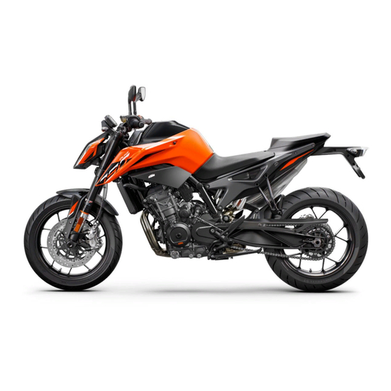
Page 22: View Of Vehicle
4 VIEW OF VEHICLE View of vehicle, front left (example) V01494-10... - Page 23 VIEW OF VEHICLE 4 Combination instrument ( p. 43) Ignition and steering lock ( p. 34) Clutch lever ( p. 28) Passenger seat Grab handle ( p. 39) Seat lock ( p. 38) Side stand ( p. 41) Shift lever ( p.
-
Page 24: View Of Vehicle, Rear Right (Example)
4 VIEW OF VEHICLE View of vehicle, rear right (example) V01493-10... - Page 25 VIEW OF VEHICLE 4 Tool set ( p. 38) Fuel tank filler cap Light switch ( p. 30) Turn signal switch ( p. 31) Horn button ( p. 32) Emergency OFF switch/electric starter button ( p. 33) Hand brake lever ( p.
-
Page 26: Serial Numbers
5 SERIAL NUMBERS Vehicle identification number The vehicle identification number is stamped on the right side of the steering head. 402324-10 Type label The type label is located on the steering head on the left. The type label Australia is located on the frame behind the 0 0 1 steering head at the top left. -
Page 27: Key Number
SERIAL NUMBERS 5 Key number can be found on the KEYCODECARD. The key number Info You need the key number to order a spare key. Keep the KEYCODECARD in a safe place. V01200-10 Engine number The engine number is stamped onto the engine case at the top. -
Page 28: Fork Part Number
5 SERIAL NUMBERS Fork part number The fork part number is stamped on the inner side of the fork stub. 402295-10 Shock absorber article number Shock absorber article number is on the left side of the shock absorber. V01201-10... -
Page 29: Steering Damper Article Number
SERIAL NUMBERS 5 Steering damper article number Steering damper article number is embossed on the underside of the steering damper. H02669-10... -
Page 30: Controls
6 CONTROLS Clutch lever Clutch lever is fitted on the handlebar on the left. V01187-10 Hand brake lever The hand brake lever is located on the right side of the han- dlebar. The front brake is engaged using the hand brake lever. V01188-10... -
Page 31: Throttle Grip
CONTROLS 6 Throttle grip The throttle grip is fitted on the right side of the handlebar. V01189-10 Switches on the left side of the handlebar 6.4.1 Combination switch The combination switch is fitted on the left side of the handlebar. -
Page 32: Light Switch
6 CONTROLS Overview of the left combination switch Light switch ( p. 30) Menu switch ( p. 31) Turn signal switch ( p. 31) Horn button ( p. 32) V01190-10 6.4.2 Light switch Light switch is fitted on the left side of the handlebar. Possible states Low beam on –... -
Page 33: Menu Switch
CONTROLS 6 6.4.3 Menu switch The menu switch is fitted in the middle of the left combination switch. The menu buttons are used to control the display on the combina- tion instrument. Button is the UP button. Button is the DOWN button. Button is the SET button. -
Page 34: Horn Button
6 CONTROLS To switch off the turn signal, press the turn signal switch towards the switch housing. 6.4.5 Horn button The horn button is fitted on the left side of the handlebar. Possible states • Horn button in neutral position pressed –... -
Page 35: Switches On The Right Side Of The Handlebar
CONTROLS 6 Switches on the right side of the handlebar 6.5.1 Emergency OFF switch/electric starter button The emergency OFF switch/electric starter button is located on the right side of the combination switch. Possible states Emergency OFF switch/electric starter button off (top position) –... -
Page 36: Ignition And Steering Lock
6 CONTROLS Ignition and steering lock The ignition and steering lock is located in front of the upper triple clamp. Possible states Ignition off – In this position, the ignition circuit is interrupted, a running engine stops, and a non-running engine will not start. The ignition key can be removed. -
Page 37: Opening Fuel Tank Filler Cap
CONTROLS 6 Opening fuel tank filler cap Danger Fire hazard Fuel is highly flammable. The fuel in the fuel tank expands when warm and can escape if overfilled. – Do not refuel the vehicle in the vicinity of open flames or lit cigarettes. –... - Page 38 6 CONTROLS Note Environmental hazard Improper handling of fuel is a danger to the environment. – Do not allow fuel to enter the groundwater, the soil, or the sewage system. – Lift cover of the fuel tank filler cap and insert the ignition key into the lock.
-
Page 39: Closing The Fuel Tank Filler Cap
CONTROLS 6 Closing the fuel tank filler cap – Fold down the fuel tank filler cap. – Turn the ignition key 90° clockwise. – Push down the fuel tank filler cap and turn the ignition key counterclockwise until the lock closes. Warning Fire hazard Fuel is highly flammable, toxic and a health hazard. -
Page 40: Seat Lock
6 CONTROLS Seat lock The seat lock is located on the left side of the vehicle. It can be locked with the ignition key. V01198-10 6.10 Tool set The tool set is located under the passenger seat. V01214-10... -
Page 41: Grab Handle
CONTROLS 6 6.11 Grab handle The grab handle is used for maneuvering the motorcycle. If you carry a passenger, the passenger can hold onto the grab handles during the trip. V01225-10 6.12 Passenger foot pegs The passenger foot pegs can be folded up and down. Possible states Passenger foot pegs folded up –... -
Page 42: Shift Lever
6 CONTROLS 6.13 Shift lever The shift lever is mounted on the left side of the engine. V01271-11 The gear positions can be seen in the photograph. The neutral or idle position is between the first and second gears. V01271-10... -
Page 43: Foot Brake Lever
CONTROLS 6 6.14 Foot brake lever Foot brake lever is located in front of the right footrest. The rear brake is engaged with the foot brake lever. 402177-10 6.15 Side stand The side stand is located on the left of the vehicle. The side stand is used for parking the motorcycle. - Page 44 6 CONTROLS Side stand folded in – This position is mandatory when riding • the motorcycle. The safety starting system is inactive.
-
Page 45: Combination Instrument 7
COMBINATION INSTRUMENT 7 Combination instrument The combination instrument is attached in front of the handlebar. The combination instrument is divided into two function areas. indicator lamps ( p. 48) Display H02851-10 Activation and test Activation The combination instrument is activated when the ignition is switched on. - Page 46 (taking care not to endanger yourself or other road users in the process) and contact an authorized KTM workshop. The oil pressure warning lamp always lights up as long as the engine is not running. If the engine is running and the...
-
Page 47: Day-Night Mode
COMBINATION INSTRUMENT 7 Day-Night mode Day mode is shown in a bright color. H02852-10 Night mode is shown in a dark color. Info The ambient light sensor in the combination instrument measures the brightness of the environment and automat- ically switches the display to day or night mode. The dis- play is brightened, darkened or switched to the other mode depending on the brightness measured by the ambient light sensor. -
Page 48: Warnings
7 COMBINATION INSTRUMENT Warnings If the general warning lamp lights up among the indicator lamps p. 48), the corresponding message appears in the display. Pressing any button confirms receipt of the information and the message is cleared. All the existing warnings are displayed in the Warnings menu until they are no longer active. - Page 49 COMBINATION INSTRUMENT 7...
-
Page 50: Indicator Lamps
7 COMBINATION INSTRUMENT Indicator lamps V01293-01... - Page 51 226) is not enabled or is currently inter- vening. The TC indicator lamp also lights up if an error is detected. Contact an authorized KTM workshop. The TC indicator lamp flashes if MTC actively engages or if the Launch Control p. 108) is activated.
- Page 52 7 COMBINATION INSTRUMENT The idle indicator lamp lights up green – The transmission is in neutral. The immobilizer indicator lamp lights up or flashes red – Status or error message of the alarm system. The oil pressure warning lamp lights up red – The oil pressure is too low. Stop immediately, taking care not to endanger yourself or other road users in the process, and switch off the engine.
- Page 53 COMBINATION INSTRUMENT 7...
-
Page 54: Display
7 COMBINATION INSTRUMENT Display H02854-10... - Page 55 COMBINATION INSTRUMENT 7 Info The figure shows the start screen of the combination instrument. If the menu is opened, the speed is still displayed. Gear display Bluetooth ® (optional) Ride Mode ( p. 225) Unit for the speedometer Fuel level display ( p.
-
Page 56: Track Display
7 COMBINATION INSTRUMENT TRACK display V01299-10... -
Page 57: Shift Warning Light
COMBINATION INSTRUMENT 7 Info The figure shows the start screen of the combination instrument in active drive mode TRACK. If the menu is opened, the speed is still displayed. Throttle response ( p. 227) Slip adjustment ( p. 227) Launch‑Control ( p. -
Page 58: Fuel Level Display
7 COMBINATION INSTRUMENT The shift warning 6,500 rpm light always lights up Fuel level display The fuel level indicator consists of bars. The more bars are lit, the more fuel is in the fuel tank. Info If the fuel level is getting low, the last bar lights up orange and the following warning LOW FUEL also appears. -
Page 59: Time
COMBINATION INSTRUMENT 7 7.10 Time The time is displayed in 24 hour format in all languages except for EN-US. The time is displayed in 12 hour format if the language is set to EN-US. The time can be configured in the Clock/Date menu. Info The time must be reset if the 12-V battery was discon- nected from the vehicle or the fuse was removed. -
Page 60: Trip Distance Counter
7 COMBINATION INSTRUMENT Emergency operation is automatically activated at 120 °C coolant temperature. Info When all the bars light up, the warning ENGINE TEMP HIGH also appears. Possible states The engine is cold – Up to three bars light up. •... -
Page 61: Menu
COMBINATION INSTRUMENT 7 7.13 Menu Info Press the SET button to open the menu. Navigate through the menu using the UP button or the DOWN button Press the BACK button to close the current menu or the menu overview. V01145-10 7.13.1 Favorites –... -
Page 62: Trip 1
7 COMBINATION INSTRUMENT 7.13.2 Trip 1 – Press the SET button when the menu is closed. – Press the UP or DOWN button until the Trips/Data menu is marked on the display. Press the SET button to open the menu. –... -
Page 63: Trip 2
COMBINATION INSTRUMENT 7 7.13.3 Trip 2 – Press the SET button when the menu is closed. – Press the UP or DOWN button until the Trips/Data menu is marked on the display. Press the SET button to open the menu. –... -
Page 64: General Info
7 COMBINATION INSTRUMENT 7.13.4 General Info Warning Danger of accidents The tire pressure monitoring sys- tem does not eliminate the necessity to check the tires before going on a ride. To avoid false alarms, the tire pressure values are evaluated over a period of several minutes. –... -
Page 65: Settings
7.13.6 Condition • The motorcycle is stationary. • Function KTM MY RIDE (optional) activated. – Press the SET button when the menu is closed. – Press the UP or DOWN button until the Trips/Data menu is marked on the display. Press the SET button to open the menu. -
Page 66: Distance
7 COMBINATION INSTRUMENT Info The Bluetooth ® function can only be used in conjunction with KTM MY RIDE (optional). If a device has been paired via the menu Pairing but is cur- rently not connected, the Bluetooth ® symbol flashes when the Bluetooth ®... -
Page 67: Temp
COMBINATION INSTRUMENT 7 7.13.8 Temp Condition • The motorcycle is stationary. – Press the SET button when the menu is closed. – Press the UP or DOWN button until the Trips/Data menu is marked on the display. Press the SET button to open the menu. –... -
Page 68: Pressure
7 COMBINATION INSTRUMENT 7.13.9 Pressure Condition • The motorcycle is stationary. • Model with TPMS. – Press the SET button when the menu is closed. – Press the UP or DOWN button until the Trips/Data menu is marked on the display. Press the SET button to open the menu. –... -
Page 69: Fuel Cons
COMBINATION INSTRUMENT 7 7.13.10 Fuel Cons Condition • The motorcycle is stationary. – Press the SET button when the menu is closed. – Press the UP or DOWN button until the Trips/Data menu is marked on the display. Press the SET button to open the menu. –... -
Page 70: Language
7 COMBINATION INSTRUMENT 7.13.11 Language Condition • The motorcycle is stationary. – Press the SET button when the menu is closed. – Press the UP or DOWN button until the Trips/Data menu is marked on the display. Press the SET button to open the menu. –... -
Page 71: Drl
COMBINATION INSTRUMENT 7 – Press the UP or DOWN button to set the clock and confirm with the SET button. – Press the UP or DOWN button to set the date and confirm with the SET button. If the 12-V battery has been disconnected, the time and date must be set. - Page 72 7 COMBINATION INSTRUMENT Warning Danger of accidents When visibility is poor, the day- time running light is not a substitute for the low beam. Automatic switching between the daytime running light and low beam may only be partially available when visibility is significantly impaired due to fog, snow or rain.
-
Page 73: Tpms Warning
COMBINATION INSTRUMENT 7 7.13.14 TPMS warning Condition • The motorcycle is stationary. • Model with TPMS. – Press the SET button when the menu is closed. – Press the UP or DOWN button until the Trips/Data menu is marked on the display. Press the SET button to open the menu. –... -
Page 74: Quick Selector 1
7 COMBINATION INSTRUMENT 7.13.15 Quick Selector 1 Condition • The motorcycle is stationary. – Press the SET button when the menu is closed. – Press the UP or DOWN button until the Trips/Data menu is marked on the display. Press the SET button to open the menu. –... -
Page 75: Quick Selector 2
COMBINATION INSTRUMENT 7 7.13.16 Quick Selector 2 Condition • The motorcycle is stationary. – Press the SET button when the menu is closed. – Press the UP or DOWN button until the Trips/Data menu is marked on the display. Press the SET button to open the menu. –... -
Page 76: Set Favorites
7 COMBINATION INSTRUMENT 7.13.17 Set Favorites Condition • The motorcycle is stationary. – Press the SET button when the menu is closed. – Press the UP or DOWN button until the Trips/Data menu is marked on the display. Press the SET button to open the menu. –... -
Page 77: Service
COMBINATION INSTRUMENT 7 7.13.18 Service Condition • The motorcycle is stationary. – Press the SET button when the menu is closed. – Press the UP or DOWN button until the Trips/Data menu is marked on the display. Press the SET button to open the menu. –... -
Page 78: Warnings
7 COMBINATION INSTRUMENT Info The optional extra functions are listed in Extra functions. The current KTM PowerParts and the available software for your vehicle can be found on the KTM website. 7.13.20 Warnings Condition • At least one warning present. -
Page 79: Ride Mode
COMBINATION INSTRUMENT 7 7.13.21 Ride Mode – Press the SET button when the menu is closed. – Press the UP or DOWN button until the Ride Mode menu is marked on the display. Press the SET button to open the menu. –... -
Page 80: Track
7 COMBINATION INSTRUMENT 7.13.22 Track Condition • The drive mode TRACK is activated. – Press the SET button when the menu is closed. – Press the UP or DOWN button until the Ride Mode menu is marked on the display. Press the SET button to open the menu. –... -
Page 81: Anti-Wheelie Mode
COMBINATION INSTRUMENT 7 7.13.23 Anti‑wheelie mode Condition • The drive mode TRACK is activated. – Press the SET button when the menu is closed. – Press the UP or DOWN button until the menu item Anti‑wheelie mo is marked on the display. Warning Danger of accidents When Anti Wheelie Mode is dis- abled, the motorcycle traction control no longer coun-... -
Page 82: Launch Control
7 COMBINATION INSTRUMENT 7.13.24 Launch control Condition • The drive mode TRACK is activated. – Press the SET button when the menu is closed. – Press the UP or DOWN button until the menu item Launch con- trol is marked on the display. –... -
Page 83: Abs
COMBINATION INSTRUMENT 7 Info Do not open the throttle when switching on or off. After the ignition is switched on, the motorcycle traction control and engine traction torque control are enabled again. 7.13.26 ABS Condition • The motorcycle is stationary. Note Voiding of the government approval for road use and the insurance coverage If the ABS is switched off completely, the vehicle's... -
Page 84: Abs Mode
7 COMBINATION INSTRUMENT Info Do not open the throttle during deactivation. After the ignition is switched back on, ABS is reacti- vated. 7.13.27 ABS Mode Condition • The motorcycle is stationary. • ABS is switched on. – Press the SET button when the menu is closed. –... -
Page 85: Quick Shift
COMBINATION INSTRUMENT 7 Info Do not open the throttle during the selection. If the ABS mode Road is enabled, ABS controls both wheels. If the ABS mode Supermoto is enabled, ABS only con- trols the front wheel. The ABS warning lamp flashes slowly to remind you that the Supermoto ABS mode is enabled. -
Page 86: Shift Light
7 COMBINATION INSTRUMENT 7.13.29 Shift Light Condition • The motorcycle is stationary. • ODO > 1,000 km (600 mi). – Press the SET button when the menu is closed. – Press the UP or DOWN button until the Motorcycle menu is marked on the display. -
Page 87: Ktm My Ride (Optional)
Press the SET button when the menu is closed. – Press the UP or DOWN button until the KTM MY RIDE menu is marked on the display. Press the SET button to open the menu. In KTM MY RIDE, an appropriate cellphone or headset can be paired via Bluetooth ®... -
Page 88: Pairing (Optional)
Press the SET button when the menu is closed. V01137-01 – Press the UP or DOWN button until the KTM MY RIDE menu is marked on the display. Press the SET button to open the menu. – Press the UP or DOWN button until Setup is marked on the dis- play. - Page 89 COMBINATION INSTRUMENT 7 – In the submenu Phone, a suitable cellphone can be paired with the KTM MY RIDE control unit. – In the submenu Headset, a suitable headset can be paired with the KTM MY RIDE control unit. –...
-
Page 90: Audio Player (Optional)
Headset connected to a suitable audio device. – Press the SET button when the menu is closed. – Press the UP or DOWN button until the KTM MY RIDE menu is marked on the display. Press the SET button to open the menu. H02860-01... - Page 91 COMBINATION INSTRUMENT 7 Warning Danger of accidents Headphone volume which is too high distracts attention from traffic activity. – Always select headphone volume which is low enough for you to still clearly hear acoustic signals. – Press the UP or DOWN button until Audio player is marked on the display.
-
Page 92: Telephony (Optional)
7 COMBINATION INSTRUMENT 7.13.33 Telephony (optional) Condition • Function KTM MY RIDE (optional) activated. • Bluetooth ® (optional) switched on. • Similarly, the Bluetooth ® function is also switched on when devices are paired. • Headset linked with appropriate cellphone. -
Page 93: Ergonomics 8
Info V01210-11 KTM recommends the front handlebar position when using the vehicle on a race track. Adjusting the handlebar position Warning Danger of accidents A repaired handlebar poses a safety risk. - Page 94 8 ERGONOMICS – Remove screws . Take off the handlebar clamps . Posi- 0 0 1 0 0 A tion the handlebar so that screws are accessible. 0 0 2 0 0 B Info 0 0 3 Cover the components to protect them against damage. 0 0 4 Do not kink the cables and lines.
-
Page 95: Adjusting The Basic Position Of The Clutch Lever
ERGONOMICS 8 Guideline Screw, handlebar 20 Nm (14.8 lbf ft) clamp Adjusting the basic position of the clutch lever – Push the clutch lever forward. – Adjust the basic position of the clutch lever to your hand size by turning adjusting screw Info Turn the adjusting screw clockwise to increase the distance between the clutch lever and the handlebar. -
Page 96: Adjusting The Basic Position Of The Hand Brake Lever
8 ERGONOMICS Adjusting the basic position of the hand brake lever – Push the hand brake lever forward. – Adjust the basic position of the hand brake lever to your hand size by turning adjusting screw Info Turn the adjusting screw clockwise to increase the distance between the hand brake lever and the han- dlebar. -
Page 97: Adjusting The Basic Position Of The Foot Brake Lever
ERGONOMICS 8 Adjusting the basic position of the foot brake lever Warning Danger of accidents The brake system fails in the event of overheating. If there is no free travel on the foot brake lever, pressure builds up in the brake system on the rear brake. - Page 98 8 ERGONOMICS Info The range of adjustment is limited. The screw must be screwed in by at least five full turns. Screwing the push rod into the ball joint adjusts the foot brake lever downwards. Screwing the push rod out of the ball joint adjusts the brake lever upwards.
-
Page 99: Checking The Basic Position Of The Shift Lever
ERGONOMICS 8 – Tighten nut Guideline Nut, push rod, foot 6 Nm (4.4 lbf ft) brake lever Press the foot brake lever downwards to make this eas- ier. V01231-10 – Attach spring Checking the basic position of the shift lever Info When driving, the shift lever must not touch the rider's boot when in the basic position. -
Page 100: Adjusting The Basic Position Of The Shift Lever
8 ERGONOMICS – Sit on the vehicle in the riding position and determine distance between the upper edge of your boot and the shift lever. Distance between shift lever 10 … 20 mm (0.39 … and upper edge of boot 0.79 in) 0 0 0 A »... - Page 101 ERGONOMICS 8 Guideline Nut, shift rod M6LH 6 Nm (4.4 lbf ft) – Tighten nut while holding threaded rod Guideline Nut, shift rod 6 Nm (4.4 lbf ft)
-
Page 102: Preparing For Use
Make sure that only tires with a similar tire tread pattern are fitted to the front and rear wheel. Warning Danger of accidents Non-approved or non-recommended tires and wheels impact the handling character- istic. – Only use tires/wheels approved by KTM with the corresponding speed index. - Page 103 When using your vehicle, remember that others may feel disturbed by excessive noise. – Make sure that the pre-sales inspection work has been carried out by an authorized KTM workshop. You receive a delivery certificate and the Service & Manufacturer Warranty Booklet at vehicle handover.
-
Page 104: Running In The Engine
9 PREPARING FOR USE – Get used to handling the motorcycle in a suitable area before making a longer trip. Try also to ride as slowly as possible to get a better feel for the motorcycle. – Hold the handlebar firmly with both hands and keep your feet on the footrests when riding. –... - Page 105 PREPARING FOR USE 9 Warning Danger of accidents Improper mounting of cases or the tank rucksack impairs the handling characteris- tic. – Mount and secure cases and tank rucksack according to the manufacturer's instructions. Warning Danger of accidents Unstable handling characteristics at high speed. –...
- Page 106 9 PREPARING FOR USE Warning Danger of accidents Pieces of luggage which have slipped impair the handling characteristic. – Check that your luggage is fixed properly at regular intervals. Warning Fire hazard The hot exhaust system may burn luggage. – Fasten your luggage in such a way that it cannot be burned or singed by the hot exhaust system. –...
-
Page 107: Riding Instructions 10
RIDING INSTRUCTIONS 10 10.1 Checks and maintenance measures when preparing for use Info Before every trip, check the condition of the vehicle and ensure that it is roadworthy. The vehicle must be in perfect technical condition when it is being operated. –... -
Page 108: Starting The Vehicle
10 RIDING INSTRUCTIONS 10.2 Starting the vehicle Danger Danger of poisoning Exhaust gases are toxic and inhaling them may result in unconsciousness and death. – Always make sure there is sufficient ventilation when running the engine. – Use effective exhaust extraction when starting or running the engine in an enclosed space. Note Engine damage High revving speed with a cold engine negatively impacts the lifespan of the engine. -
Page 109: Starting Off
RIDING INSTRUCTIONS 10 – Turn the emergency OFF switch/electric starter button to the lower position Info Do not press the emergency off switch/electric starter button into the lower position until the combination instrument function check has been completed. When starting, DO NOT open the throttle. If you open the throttle during the starting procedure, fuel is not injected by the engine management system and the engine cannot start. -
Page 110: Launch-Control
10 RIDING INSTRUCTIONS 10.4 Launch‑Control Launch Control is a vehicle electronics function. Launch control adjusts the engine speed in order to achieve the best possible acceleration. Launch control can be used for starting off for a maximum of three times in succession. Launch control is temporarily deactivated after the third starting off in order to protect the engine, transmis- sion and cooling system from overloading. - Page 111 RIDING INSTRUCTIONS 10 Condition The drive mode TRACK is activated. First gear is engaged. The TC indicator lamp does not light up. Coolant temperature: > 60 °C (> 140 °F) Total riding distance covered: > 1,000 km (> 620 mi) –...
-
Page 112: Quickshifter
10 RIDING INSTRUCTIONS 10.6 Quickshifter + If the quickshifter + is activated, you can shift up and down with- out actuating the clutch. Because there is no need to close the throttle grip, uninterrupted gear shifts are possible. The quickshifter + uses the shifter shaft position to check whether or not a shift should be initiated, and sends a corresponding signal to the engine control. -
Page 113: Shifting, Riding
RIDING INSTRUCTIONS 10 10.7 Shifting, riding Warning Danger of accidents Abrupt load alterations can cause the vehicle to get out of control. – Avoid abrupt load alterations and sudden braking actions. – Adapt your speed to the road conditions. Warning Danger of accidents If you change down at high engine speed, the rear wheel blocks and the engine races. - Page 114 10 RIDING INSTRUCTIONS Warning Risk of injury The passenger may fall from the motorcycle if they conduct themselves incorrectly. – Ensure that the passenger sits correctly on the passenger seat, places his or her feet on the passenger foot pegs and holds on to the rider or the grab handles. –...
- Page 115 RIDING INSTRUCTIONS 10 Warning Danger of accidents Total weight and axle loads influence the handling characteristic. The total weight consists of: motorcycle ready for operation and with a full tank, driver and passenger with protective clothing and helmet, and luggage. – Do not exceed the maximum permissible overall weight or the axle loads.
- Page 116 Info If unusual noises occur while riding, stop immediately (taking care not to endanger yourself or other road users in the process), switch off the engine and contact an authorized KTM workshop. – Shift into a higher gear when conditions allow (incline, road situation, etc.).
- Page 117 Contact an authorized KTM workshop. – If the malfunction indicator lamp lights up during a trip, please contact an authorized KTM workshop as soon as possi- ble. – If the general warning lamp lights up during a trip, the dis-...
- Page 118 10 RIDING INSTRUCTIONS Info Very important messages are stored in the Warnings menu. – If the ice warning appears in the combination instrument, the roads may be icy. Adjust your speed to the road conditions. – If the quickshifter + is enabled in the combination instrument, you can shift up in the speed range shown without pulling the clutch lever.
-
Page 119: Engine Traction Torque Control (Msr)
RIDING INSTRUCTIONS 10 – If the quickshifter + is enabled in the combination instrument, you can shift down in the speed range shown without pulling the clutch lever. Info The maximum engine speed before shifting down in revolutions per minute is shown in the figure. Depress the shift lever quickly back to the stop without changing the throttle twist grip position. -
Page 120: Applying The Brakes
Danger of accidents A spongy pressure point on the front or rear brake reduces braking efficiency. – Check the brake system and do not continue riding until the problem is eliminated. (Your authorized KTM workshop will be glad to help.) Warning Danger of accidents The brake system fails in the event of overheating. - Page 121 RIDING INSTRUCTIONS 10 Warning Danger of accidents ABS may increase the stopping distance in certain situations. – Adjust application of the brakes to the respective riding situation and riding surface conditions. Warning Danger of accidents Excessively forceful application of the brakes blocks the wheels. The ABS effectiveness is only ensured if it is switched on.
-
Page 122: Stopping, Parking
10 RIDING INSTRUCTIONS – Braking should always be completed before you go into a bend. Change down to a lower gear appropriate to your road speed. – On long downhill stretches, use the braking effect of the engine. Change down one or two gears, but do not over rev the engine. - Page 123 RIDING INSTRUCTIONS 10 Significant damage may be caused if the vehicle rolls away or falls over. The components for parking the vehicle are designed only for the weight of the vehicle. – Park the vehicle on a firm and level surface. –...
-
Page 124: Transporting
10 RIDING INSTRUCTIONS 10.11 Transporting Note Danger of damage The parked vehicle can roll away or fall over. – Park the vehicle on a firm and level surface. Note Fire hazard Hot vehicle components pose a fire hazard and explosion risk. – Do not park the vehicle near to materials which are highly flammable or explosive. -
Page 125: Refueling
RIDING INSTRUCTIONS 10 10.12 Refueling Danger Fire hazard Fuel is highly flammable. The fuel in the fuel tank expands when warm and can escape if overfilled. – Do not refuel the vehicle in the vicinity of open flames or lit cigarettes. –... - Page 126 In some countries and regions, the available fuel quality and cleanliness may not be sufficient. This will result in problems with the fuel system. – Refuel only with clean fuel that meets the specified standards. (Your authorized KTM workshop will be glad to help.) Note Environmental hazard Improper handling of fuel is a danger to the environment.
- Page 127 RIDING INSTRUCTIONS 10 – Switch off the engine. – Open fuel tank filler cap. ( p. 35) – Fill the fuel tank with fuel up to the lower edge of the filler neck. Total fuel tank 14 l Super unleaded capacity, approx.
-
Page 128: Service Schedule
Different service intervals may apply in your country, depending on the local operating conditions. Individual service intervals and scopes may change in the course of technical developments. The most up-to-date service schedule can always be found on KTM Dealer.net. Your authorized KTM dealer will be happy to advise you. - Page 129 SERVICE SCHEDULE 11 Every two years Every year every 30,000 km (18,600 mi) every 15,000 km (9,300 mi) after 1,000 km (620 mi) ○ ● ● ● Check the front brake fluid level. ( p. 155) ○ ● ● ● Check the rear brake fluid level.
- Page 130 Final check: Check the vehicle is roadworthy and take a test ride. ○ ● ● ● ● Read out the fault memory using the KTM diagnostics tool after a test ride. ○ ● ● ● ● Set the service interval display.
-
Page 131: Recommended Work
SERVICE SCHEDULE 11 11.3 Recommended work Every four years Every year every 30,000 km (18,600 mi) every 15,000 km (9,300 mi) after 1,000 km (620 mi) ● Check the frame. ● Check the swingarm. ○ ● ● Check/clean the oil nozzle for clutch lubrication. ●... -
Page 132: Tuning The Chassis
12 TUNING THE CHASSIS 12.1 Adjusting the spring preload of the shock absorber Warning Danger of accidents Modifications to the suspension setting may seriously alter the handling characteris- tic. – Ride slowly to start with after making adjustments to get the feel of the new handling characteristic. Info The spring preload defines the initial status of the spring operation on the shock absorber. -
Page 133: Service Work On The Chassis 13
SERVICE WORK ON THE CHASSIS 13 13.1 Raising the motorcycle with the rear lifting gear Note Danger of damage The parked vehicle can roll away or fall over. – Park the vehicle on a firm and level surface. – Mount the supports of the lifting gear. –... -
Page 134: Lifting The Motorcycle With The Front Lifting Gear
13 SERVICE WORK ON THE CHASSIS – Secure the motorcycle against falling over. – Remove the rear lifting gear and lean the vehicle on side stand 402029-10 13.3 Lifting the motorcycle with the front lifting gear Note Danger of damage The parked vehicle can roll away or fall over. –... -
Page 135: Taking The Motorcycle Off The Front Lifting Gear
SERVICE WORK ON THE CHASSIS 13 Main work – Move the handlebar to the straight-ahead position. Align the lifting gear at the front with the adapters to the fork legs. Front wheel work stand, small (61129965100) Info Always raise the motorcycle at the rear first. –... -
Page 136: Cleaning The Dust Boots Of The Fork Legs
13 SERVICE WORK ON THE CHASSIS – Secure the motorcycle against falling over. – Remove the front lifting gear. 312029-10 13.5 Cleaning the dust boots of the fork legs Preparatory work – Raise the motorcycle with the rear lifting gear. ( p. - Page 137 SERVICE WORK ON THE CHASSIS 13 Warning Danger of accidents Oil or grease on the brake discs reduces the braking effect. – Always keep the brake discs free of oil and grease. – Clean the brake discs with brake cleaner when nec- essary.
-
Page 138: Removing The Passenger Seat
13 SERVICE WORK ON THE CHASSIS 13.6 Removing the passenger seat – Insert the ignition key in seat lock and turn it clockwise. – Raise the rear of the passenger seat cover, push it toward the rear, and remove it upward. –... -
Page 139: Mounting The Passenger Seat
SERVICE WORK ON THE CHASSIS 13 13.7 Mounting the passenger seat – Hook holding lugs of the passenger seat onto the storage compartment, lower the rear and push forward. – Press passenger seat downward until it clicks into place. Warning Danger of accidents The seat can come loose from the anchoring if it is not mounted correctly. -
Page 140: Removing The Front Rider's Seat
13 SERVICE WORK ON THE CHASSIS 13.8 Removing the front rider's seat Preparatory work – Remove the passenger seat. ( p. 136) Main work – Remove screws – Raise the rear of the front rider's seat, pull the seat back, and lift it off. -
Page 141: Mounting The Front Rider's Seat
SERVICE WORK ON THE CHASSIS 13 13.9 Mounting the front rider's seat Main work – Push the front rider's seat forward and lower at the rear. The holding lugs engage in the loops on the tank. The holding lugs engage in the loops on the frame. -
Page 142: Checking The Chain For Dirt
13 SERVICE WORK ON THE CHASSIS – Mount and tighten screws Guideline Remaining screws, 10 Nm (7.4 lbf ft) chassis – Finally, check that the front rider's seat is correctly mounted. V01239-11 Finishing work – Mount the passenger seat. ( p. -
Page 143: Cleaning The Chain
SERVICE WORK ON THE CHASSIS 13 13.11 Cleaning the chain Warning Danger of accidents Lubricants on the tires reduces the road grip. – Remove lubricants from the tires using a suitable cleaning agent. Warning Danger of accidents Oil or grease on the brake discs reduces the braking effect. –... - Page 144 13 SERVICE WORK ON THE CHASSIS Main work – Rinse off loose dirt with a soft jet of water. – Remove old grease residue with chain cleaner. Chain cleaner ( p. 274) – After drying, apply chain spray. Street chain spray ( p.
-
Page 145: Checking The Chain Tension
SERVICE WORK ON THE CHASSIS 13 13.12 Checking the chain tension Warning Danger of accidents Incorrect chain tension damages components and results in accidents. If the chain is tensioned too much, the chain, engine sprocket, rear sprocket, transmission and rear wheel bearings wear more quickly. Some components may break if overloaded. If the chain is too loose, the chain may fall off the engine sprocket or the rear sprocket. - Page 146 13 SERVICE WORK ON THE CHASSIS Main work – Shift the transmission to neutral position. – Push the chain behind the chain sliding piece up and deter- mine the chain tension between the swingarm and the upper edge of the chain. Guideline 2.5 cm (0.98 in) Distance...
-
Page 147: Adjusting The Chain Tension
SERVICE WORK ON THE CHASSIS 13 13.13 Adjusting the chain tension Warning Danger of accidents Incorrect chain tension damages components and results in accidents. If the chain is tensioned too much, the chain, engine sprocket, rear sprocket, transmission and rear wheel bearings wear more quickly. Some components may break if overloaded. If the chain is too loose, the chain may fall off the engine sprocket or the rear sprocket. - Page 148 13 SERVICE WORK ON THE CHASSIS Main work – Loosen nut – Loosen nuts – Adjust the chain tension by turning adjusting screws left and right. Guideline Chain tension 2 … 5 mm (0.08 … 0.2 in) Turn the adjusting screws on the left and right so that the markings on the left and right chain adjusters are in...
-
Page 149: Checking The Chain, Rear Sprocket, Engine Sprocket, And Chain Guide
SERVICE WORK ON THE CHASSIS 13 Guideline Nut, rear wheel M25x1.5 90 Nm (66.4 lbf ft) Thread and contact area spindle of wheel spindle greased Finishing work – Check the chain tension. ( p. 143) – Remove the rear of the motorcycle from the lifting gear. p. - Page 150 13 SERVICE WORK ON THE CHASSIS – Shift the transmission to neutral position. – Pull on the lower chain section with the specified weight Guideline Weight of chain wear mea- 15 kg (33 lb.) surement – Measure distance of 18 chain rollers in the lower chain section.
- Page 151 SERVICE WORK ON THE CHASSIS 13 – Check the engine sprocket cover for wear. » If the engine sprocket cover is highly worn in the marked area – Change the engine sprocket cover. – Check the engine sprocket cover for tightness. »...
- Page 152 13 SERVICE WORK ON THE CHASSIS – Check the chain sliding guard for wear. » If continuous signs of wear to the chain are visible on the chain sliding guard in the area marked: – Replace the chain sliding guard. »...
-
Page 153: Brake System 14
Do not make any changes to the suspension travel. – Only use spare parts on the brake system which have been approved and recommended by KTM. – Only use tires/wheels approved by KTM with the corre- sponding speed index. – Maintain the specified tire pressure. –... - Page 154 14 BRAKE SYSTEM Note Voiding of the government approval for road use and the insurance coverage If the ABS is switched off completely, the vehicle's approval for road use is invalidated. – Only operate the vehicle in closed-off areas remote from public road traffic if the ABS is switched off completely.
-
Page 155: Checking The Brake Discs
ABS warning lamp goes out after starting off. 14.2 Checking the brake discs Warning Danger of accidents Worn-out brake discs reduce the braking effect. – Make sure that worn-out brake discs are replaced immediately. (Your authorized KTM workshop will be glad to help.) - Page 156 14 BRAKE SYSTEM – Check the front and rear brake disc thickness at multiple points for the dimension Info Wear will reduce the thickness of the brake disc at con- tact surface of the brake linings. Brake discs - wear limit front 4.5 mm (0.177 in) 100135-10...
-
Page 157: Checking The Front Brake Fluid Level
– Make sure that brake fluid for the front and rear brake is changed in accordance with the service schedule. (Your authorized KTM workshop will be glad to help.) – Move the brake reservoir mounted on the handlebar to a hori- zontal position. -
Page 158: Adding Front Brake Fluid
– Check the brake system and do not continue riding until the problem is eliminated. (Your authorized KTM workshop will be glad to help.) Warning Skin irritation Brake fluid causes skin irritation. –... - Page 159 Danger of accidents Old brake fluid reduces the braking effect. – Make sure that brake fluid for the front and rear brake is changed in accordance with the service schedule. (Your authorized KTM workshop will be glad to help.) Note Environmental hazard Hazardous substances cause environmental damage.
-
Page 160: Checking The Front Brake Linings
Clean up overflowed or spilled brake fluid immediately with water. 14.5 Checking the front brake linings Warning Danger of accidents Worn-out brake linings reduce the braking effect. – Ensure that worn-out brake linings are replaced immediately. (Your authorized KTM workshop will be glad to help.) - Page 161 BRAKE SYSTEM 14 Warning Danger of accidents Damaged brake discs reduce the braking effect. If the brake linings are not changed in time, the brake lining carriers grind against the brake disc. As a consequence, the braking effect is greatly reduced and the brake discs are destroyed. –...
-
Page 162: Checking The Free Travel Of The Foot Brake Lever
14 BRAKE SYSTEM 14.6 Checking the free travel of the foot brake lever Warning Danger of accidents The brake system fails in the event of overheating. If there is no free travel on the foot brake lever, pressure builds up in the brake system on the rear brake. -
Page 163: Checking The Rear Brake Fluid Level
Danger of accidents Old brake fluid reduces the braking effect. – Make sure that brake fluid for the front and rear brake is changed in accordance with the service schedule. (Your authorized KTM workshop will be glad to help.) – Stand the vehicle upright. -
Page 164: Adding Rear Brake Fluid
If the brake fluid level drops below the MIN marking, the brake system is leaking or the brake linings are worn down. – Check the brake system and do not continue riding until the problem is eliminated. (Your authorized KTM workshop will be glad to help.) Warning Skin irritation Brake fluid causes skin irritation. –... - Page 165 Danger of accidents Old brake fluid reduces the braking effect. – Make sure that brake fluid for the front and rear brake is changed in accordance with the service schedule. (Your authorized KTM workshop will be glad to help.) Note Environmental hazard Hazardous substances cause environmental damage.
-
Page 166: Checking The Rear Brake Linings
Clean up overflowed or spilled brake fluid immediately with water. 14.9 Checking the rear brake linings Warning Danger of accidents Worn-out brake linings reduce the braking effect. – Ensure that worn-out brake linings are replaced immediately. (Your authorized KTM workshop will be glad to help.) - Page 167 BRAKE SYSTEM 14 Warning Danger of accidents Damaged brake discs reduce the braking effect. If the brake linings are not changed in time, the brake lining carriers grind against the brake disc. As a consequence, the braking effect is greatly reduced and the brake discs are destroyed. –...
-
Page 168: Wheels, Tires
15 WHEELS, TIRES 15.1 Removing the front wheel Preparatory work – Raise the motorcycle with the rear lifting gear. ( p. 131) – Lift the motorcycle with the front lifting gear. ( p. 132) Main work – Remove screw and pull wheel speed sensor out of the hole. - Page 169 WHEELS, TIRES 15 – Loosen screw by several rotations. – Loosen screws – Press on screw to push the wheel spindle out of the axle clamp. – Remove screw Warning Danger of accidents Damaged brake discs reduce the V01244-10 braking effect. –...
-
Page 170: Installing The Front Wheel
15 WHEELS, TIRES 15.2 Installing the front wheel Warning Danger of accidents Oil or grease on the brake discs reduces the braking effect. – Always keep the brake discs free of oil and grease. – Clean the brake discs with brake cleaner when necessary. –... - Page 171 WHEELS, TIRES 15 – Insert wide spacer on the left in the direction of travel. – Insert narrow spacer on the right in the direction of travel. Info Arrow indicates the direction of travel of the front wheel. The ABS sensor wheel is on the left viewed in the direc- tion of travel.
- Page 172 15 WHEELS, TIRES – Clean screw and the wheel spindle. – Grease wheel spindle lightly. Long-life grease ( p. 274) – Jack up the front wheel into the fork, position it, and insert the wheel spindle. – Mount and tighten screw Guideline Screw, front M25x1.5...
- Page 173 WHEELS, TIRES 15 – Position both brake calipers. The brake linings are correctly positioned. – Mount screws on both sides but do not tighten yet. Guideline Screw, front M10x1.25 45 Nm (33.2 lbf ft) Loctite ® 243™ brake caliper – Operate the hand brake lever repeatedly until the brake lin- ings are in contact with the brake disc and there is a pressure point.
-
Page 174: Removing The Rear Wheel
15 WHEELS, TIRES – Remove the rear of the motorcycle from the lifting gear. p. 131) – Operate the front brake and compress the fork a few times firmly. The fork legs straighten. – Tighten screws Guideline Screw, fork stub 15 Nm (11.1 lbf ft) V01268-10 15.3... - Page 175 WHEELS, TIRES 15 Main work – Press the brake caliper onto the brake disc by hand in order to push back the brake piston. – Remove screw and pull wheel speed sensor out of the hole. – Remove nut . Remove chain adjuster –...
- Page 176 15 WHEELS, TIRES – Push the rear wheel forward as far as possible. Remove the chain from the rear sprocket. Info Cover the components to protect them against damage. – Hold the rear wheel and remove the wheel spindle. – Pull the rear wheel back until the brake caliper bracket is sus- pended freely between the brake disc and rim.
-
Page 177: Installing The Rear Wheel
WHEELS, TIRES 15 15.4 Installing the rear wheel Warning Danger of accidents Oil or grease on the brake discs reduces the braking effect. – Always keep the brake discs free of oil and grease. – Clean the brake discs with brake cleaner when necessary. Warning Danger of accidents There is no braking effect to start with at the rear brake after installing the rear wheel. - Page 178 15 WHEELS, TIRES – Clean and grease the thread of the wheel spindle and nut. Long-life grease ( p. 274) – Clean and grease the wheel spindle. Long-life grease ( p. 274) – Clean the contact areas on the brake caliper bracket and swingarm.
- Page 179 WHEELS, TIRES 15 – Engage the thrust bearing of brake caliper bracket and the swingarm. – Jack up the rear wheel into the swingarm, position it, and insert the wheel spindle. The brake linings are correctly positioned. – Place the chain on the sprocket. –...
-
Page 180: Checking The Rear Hub Damping Rubber Pieces
15 WHEELS, TIRES Guideline Remaining screws, 10 Nm (7.4 lbf ft) chassis – Operate the foot brake lever repeatedly until the brake lin- ings are in contact with the brake disc and there is a pressure point. Finishing work – Check the chain tension. - Page 181 WHEELS, TIRES 15 Main work – Check bearing » If the bearing is damaged or worn: – Change the bearing of the rear sprocket carrier. – Check the damping rubber pieces of the rear hub for dam- age and wear. »...
-
Page 182: Checking The Tire Condition
Warning Danger of accidents If a tire bursts while riding, the vehicle becomes uncontrollable. – Ensure that damaged or worn tires are replaced immediately. (Your authorized KTM workshop will be glad to help.) Warning Danger of crashing Different tire tread patterns on the front and rear wheel impair the handling charac- teristic. - Page 183 WHEELS, TIRES 15 Warning Danger of accidents New tires have reduced road grip. The contact surface on new tires is not yet roughened. – Run in new tires with moderate riding at alternating angles. Running-in phase 200 km (124 mi) Info The type, condition, and pressure of the tires all have a major impact on the handling characteristic of the motorcycle.
-
Page 184: Checking Tire Pressure
DOT number. The first two digits indicate the week of manufacture and the last two digits the year of manu- facture. KTM recommends that the tires be changed after 5 H01144-10 years at the latest, regardless of the actual state of wear. - Page 185 WHEELS, TIRES 15 – Remove the protection cap. – Check the tire pressure when the tires are cold. Tire pressure when solo front 2.3 bar (33 psi) rear 2.6 bar (38 psi) Tire pressure with passenger / full payload front 2.3 bar (33 psi) 400695-01 rear...
-
Page 186: Using Tire Repair Spray
15 WHEELS, TIRES 15.8 Using tire repair spray Warning Danger of accidents Incorrect use of tire repair spray will result in the repaired tire losing pressure. Tire repair spray cannot be used for all types of damage. – Observe the instructions and specifications of the manufacturer of the tire repair spray. -
Page 187: Electrical System 16
ELECTRICAL SYSTEM 16 16.1 Daytime running light (DRL) Warning Danger of accidents When visibility is poor, the daytime running light is not a substitute for the low beam. Automatic switching between the daytime running light and low beam may only be partially available when visi- bility is significantly impaired due to fog, snow or rain. -
Page 188: Removing The 12-V Battery
16 ELECTRICAL SYSTEM This is controlled by the ambient light sensor in the combination instrument. When visibility conditions are good, the low beam is switched off and the daytime running light is switched on. Info The position light lights up with all types of lighting. 16.2 Removing the 12-V battery Warning... - Page 189 ELECTRICAL SYSTEM 16 Main work – Disconnect negative cable from the 12-V battery. – Remove positive terminal cover V01203-11...
- Page 190 16 ELECTRICAL SYSTEM – Disconnect positive cable from the 12-V battery. – Take negative cable out of holders on the battery support bracket. – Remove screw – Pull battery support bracket to the side. – Pull the 12-V battery upwards and out of the battery compart- ment.
-
Page 191: Installing The 12-V Battery
ELECTRICAL SYSTEM 16 16.3 Installing the 12-V battery Main work – Position the 12-V battery in the battery compartment. 12 V battery (HTZ12A-BS) ( p. 260) The battery terminals face opposite the direction of travel. – Position battery support bracket –... - Page 192 16 ELECTRICAL SYSTEM – Mount positive terminal cover – Connect negative cable to the 12 V battery. Guideline Screw, battery termi- M6x12 4.5 Nm (3.32 lbf ft) V01203-10 Finishing work – Mount the passenger seat. ( p. 137) – Set the time and date.
-
Page 193: Charging The 12-V Battery
ELECTRICAL SYSTEM 16 16.4 Charging the 12-V battery Warning Risk of injury Battery acid and battery gases cause serious chemical burns. – Keep 12 V batteries out of the reach of children. – Wear suitable protective clothing and safety glasses. – Avoid contact with battery acid and battery gases. - Page 194 16 ELECTRICAL SYSTEM Info Even when there is no load on the 12-V battery, it discharges steadily each day. The charging level and the method of charging are very important for the service life of the 12-V battery. Rapid recharging with a high charging current shortens the service life of the battery. If the charging current, charging voltage, or charging time is exceeded, electrolyte escapes through the safety valves.
- Page 195 ELECTRICAL SYSTEM 16 Main work – Disconnect negative cable of the 12-V battery to avoid damaging the onboard electronics. – Remove positive terminal cover V01203-11 – Connect the battery charger to the 12-V battery. Switch on the battery charger. Battery charger (58429074000) You can also use the battery charger to test the open-circuit voltage and starting ability of the 12-V battery, and to test the alternator.
- Page 196 16 ELECTRICAL SYSTEM Guideline The charging current, charging voltage, and charging time must not be exceeded. Recharge the 12-V battery 3 months regularly when the motorcy- cle is not being used – Mount positive terminal cover – Connect negative cable to the 12 V battery.
-
Page 197: Changing The Main Fuse
ELECTRICAL SYSTEM 16 16.5 Changing the main fuse Warning Fire hazard Incorrect fuses overload the electrical system. – Only use fuses with the required ampere value. – Do not bypass or repair fuses. Info The main fuse protects all power consumers of the vehicle. The main fuse is under the passenger seat. Preparatory work –... - Page 198 16 ELECTRICAL SYSTEM Main work – Remove protection cap V01205-10 – Remove faulty main fuse Info A faulty fuse has a burned-out fuse wire A spare fuse is located in the starter relay. – Insert a new main fuse. Fuse (58011109130) ( p.
-
Page 199: Changing Abs Fuses
ELECTRICAL SYSTEM 16 – Mount protection cap V01205-10 Finishing work – Mount the passenger seat. ( p. 137) – Set the time and date. 16.6 Changing ABS fuses Warning Fire hazard Incorrect fuses overload the electrical system. – Only use fuses with the required ampere value. –... - Page 200 16 ELECTRICAL SYSTEM Info Two fuses for the ABS are located under the passenger seat. These fuses protect the return pump and the hydraulic unit of the ABS. The third fuse, which protects the ABS control unit, is located in the fuse box. Preparatory work –...
-
Page 201: Changing The Fuses Of Individual Power Consumers
ELECTRICAL SYSTEM 16 To change the fuse of the ABS return pump: – Remove the protection cap and fuse Info A faulty fuse has a burned-out fuse wire – Insert a spare fuse with the correct rating. Fuse (75011088025) ( p. - Page 202 16 ELECTRICAL SYSTEM Info The fuse box containing the fuses of individual power consumers is located under the seat. Preparatory work – Switch off the ignition by turning the ignition key to the posi- tion – Remove the passenger seat. ( p.
- Page 203 ELECTRICAL SYSTEM 16 – Remove the faulty fuse. Guideline Fuse 1 - 10 A - ignition Fuse 2 - 10 A - ignition, engine electronics control unit, electronic fuel injection, evaporate emission control system, lambda sensor, immobilizer/alarm system Fuse 3 - 10 A - fuel pump Fuse 4 - 10 A - radiator fan V01208-10 Fuse 5 - 10 A - horn, combination instrument, brake light...
-
Page 204: Loosening The Headlight Mask With The Headlight
16 ELECTRICAL SYSTEM Replace the spare fuse in the fuse box so that it is available if needed. – Check that the power consumer is functioning properly. – Close the fuse box cover. Finishing work – Mount the passenger seat. ( p. -
Page 205: Mounting The Headlight Mask With The Headlight
ELECTRICAL SYSTEM 16 – Swivel the headlight mask forwards slightly and disconnect connector – Swivel the headlight mask all the way forwards. V01217-10 16.9 Mounting the headlight mask with the headlight Main work – Swivel the headlight mask up. – Plug in connector –... -
Page 206: Removing The Cover Of The Headlight Mask Rack
16 ELECTRICAL SYSTEM – Mount adjusting screw V01212-11 Finishing work – Check the headlight setting. ( p. 208) 16.10 Removing the cover of the headlight mask rack Info The cover of the headlight mask rack must be removed in order to gain access to the ACC1 and ACC2 power supply. - Page 207 ELECTRICAL SYSTEM 16 Main work – Remove screws – Remove screws V01218-10...
-
Page 208: Installing The Cover Of The Headlight Mask Rack
16 ELECTRICAL SYSTEM – Hold turn signal in the area and carefully press against the direction of travel. The cover is detached as illustrated. – Repeat the operation on the opposite side. – Take off the cover. V01219-10 16.11 Installing the cover of the headlight mask rack Main work –... - Page 209 ELECTRICAL SYSTEM 16 – Mount and tighten screws Guideline Remaining screws, 5 Nm (3.7 lbf ft) chassis – Mount and tighten screws Guideline Screw, headlight EJOTPT ® 2 Nm (1.5 lbf ft) K50x14 V01218-10 Finishing work – Mount the headlight mask with the headlight. ( p.
-
Page 210: Checking The Headlight Setting
16 ELECTRICAL SYSTEM 16.12 Checking the headlight setting – Position the vehicle upright on a horizontal surface in front of a light wall and make a marking at the height of the center of the low beam headlight. – Make another mark at a distance under the first marking. -
Page 211: Adjusting The Headlight Range
ELECTRICAL SYSTEM 16 16.13 Adjusting the headlight range Preparatory work – Check the headlight setting. ( p. 208) Main work – Turn adjusting screw to adjust the headlight range. Info Turn clockwise to increase the headlight range; turn counterclockwise to reduce the headlight range. If you have a payload, you may have to correct the headlight range. -
Page 212: Diagnostics Connector
A diagnosis adapter has been connected in the factory for con- nection with diagnosis interface which applies to all manufac- turers. Info Remove the diagnosis adapter to use the KTM diagno- sis tool. H02681-10 Following completion of the diagnostics, plug the diag- nostics adapter back in. -
Page 213: Acc1 And Acc2 Rear
ELECTRICAL SYSTEM 16 16.16 ACC1 and ACC2 rear Installation location – The rear power supplies ACC1 and ACC2 are located under the passenger seat next to the battery compartment. V01215-10... -
Page 214: Cooling System
17 COOLING SYSTEM 17.1 Cooling system Water pump in the engine ensures forced circulation of the coolant. The pressure resulting from the warming of the cooling system is regulated by a valve in radiator cap . Heat expansion causes excess coolant to flow into compensating tank . -
Page 215: Checking The Antifreeze And Coolant Level
COOLING SYSTEM 17 17.2 Checking the antifreeze and coolant level Warning Danger of scalding During motorcycle operation, the coolant gets very hot and is under pressure. – Do not open the radiator, the radiator hoses or other cooling system components if the engine or the cooling system are at operating temperature. - Page 216 17 COOLING SYSTEM Main work – Remove radiator cap and cap of the compensating tank. – Check the antifreeze in the coolant. −25 … −45 °C (−13 … Antifreeze −49 °F) » If the antifreeze in the coolant does not match the speci- fied value: V01255-10 –...
-
Page 217: Checking The Coolant Level In The Compensating Tank
COOLING SYSTEM 17 The radiator must be filled completely. » If the coolant level does not match the specified value: – Check the coolant level and the reason for the loss. » If you had to add more coolant than the specified amount: >... - Page 218 17 COOLING SYSTEM Warning Danger of poisoning Coolant is toxic and a health hazard. – Keep coolant out of the reach of children. – Do not allow coolant to come into contact with the skin, the eyes and clothing. – Consult a doctor immediately if coolant is swallowed. –...
-
Page 219: Draining The Coolant
COOLING SYSTEM 17 » If there is no coolant in the compensating tank: – Check the cooling system for leaks. Info Do not start up the motorcycle! – Fill/bleed the cooling system. p. 219) 17.4 Draining the coolant Warning Danger of scalding During motorcycle operation, the coolant gets very hot and is under pressure. –... - Page 220 17 COOLING SYSTEM Warning Danger of poisoning Coolant is toxic and a health hazard. – Keep coolant out of the reach of children. – Do not allow coolant to come into contact with the skin, the eyes and clothing. – Consult a doctor immediately if coolant is swallowed. –...
-
Page 221: Filling/Bleeding The Cooling System
COOLING SYSTEM 17 17.5 Filling/bleeding the cooling system Warning Danger of poisoning Coolant is toxic and a health hazard. – Keep coolant out of the reach of children. – Do not allow coolant to come into contact with the skin, the eyes and clothing. –... - Page 222 17 COOLING SYSTEM – Remove bleeder screw – Tilt the vehicle slightly to the right. – Pour in coolant until it emerges without bubbles at the vent hole, and then mount and tighten bleeder screw immedi- ately. Coolant 1.20 l Coolant ( p.
-
Page 223: Change The Coolant
COOLING SYSTEM 17 – When the engine is cool, check the coolant level in the radiator and, if necessary, add coolant. – Check the coolant level in the compensating tank. ( p. 215) 17.6 Change the coolant Warning Danger of scalding During motorcycle operation, the coolant gets very hot and is under pressure. –... - Page 224 17 COOLING SYSTEM – Position the motorcycle upright. – Place an appropriate container under the engine. – Remove screw with the seal ring. V01254-11 – Remove radiator cap – Completely drain the coolant. – Mount and tighten screw with a new seal ring. Guideline Screw plug, EJOTALtracs...
- Page 225 COOLING SYSTEM 17 – Remove bleeder screw – Tilt the vehicle slightly to the right. – Pour in coolant until it emerges without bubbles at the vent hole, and then mount and tighten bleeder screw immedi- ately. Coolant 1.20 l Coolant ( p.
- Page 226 17 COOLING SYSTEM – After the engine has cooled down, check the coolant level in the radiator and in the compensating tank again and add more coolant if necessary.
-
Page 227: Tuning The Engine 18
TUNING THE ENGINE 18 18.1 Ride Mode Possible states SPORT – Homologated performance with very direct response; • the motorcycle traction control allows greater slip on the rear wheel. STREET – Homologated performance with balanced response; • the motorcycle traction control allows normal slip on the rear wheel. -
Page 228: Motorcycle Traction Control (Mtc)
18 TUNING THE ENGINE 18.2 Motorcycle traction control (MTC) The motorcycle traction control (MTC) lowers the engine torque in case of loss of traction in the rear wheel. Info When motorcycle traction control is switched off, the rear wheel may spin during strong acceleration and on surfaces with low grip, resulting in a risk of crashing. -
Page 229: Slip Adjustment
TUNING THE ENGINE 18 18.3 Slip adjustment The slip adjustment is a motorcycle traction control function. The slip adjustment allows the motorcycle traction control to be tuned through nine levels to the desired characteristic map. Level 1 allows the maximum slip on the rear wheel, and level 9 the minimum. - Page 230 18 TUNING THE ENGINE Info Throttle response is only available in drive mode TRACK.
-
Page 231: Service Work On The Engine 19
SERVICE WORK ON THE ENGINE 19 19.1 Checking the engine oil level Info The engine oil level must be checked at normal engine operating temperature. – Stand the motorcycle upright on a horizontal surface. – Check the engine oil level. Info After switching off the engine, wait one minute before checking the level. -
Page 232: Changing The Engine Oil And Oil Filter, Cleaning The Oil Screens
19 SERVICE WORK ON THE ENGINE 19.2 Changing the engine oil and oil filter, cleaning the oil screens Warning Danger of scalding Engine and gear oil get very hot when the motorcycle is ridden. – Wear suitable protective clothing and safety gloves. –... - Page 233 SERVICE WORK ON THE ENGINE 19 Main work – Rest the motorcycle on its side stand on a horizontal surface. – Place an appropriate container under the engine. – Remove oil filler plug with the O-ring from the clutch cover. H01066-10 –...
- Page 234 19 SERVICE WORK ON THE ENGINE – Remove screws . Take off oil filter cover with the O- ring. – Pull oil filter out of the oil filter housing. Lock ring plier (51012011000) – Completely drain the engine oil. – Thoroughly clean the parts and sealing surfaces.
- Page 235 SERVICE WORK ON THE ENGINE 19 – Thoroughly clean magnets and oil screens of the oil drain plugs. V01238-10 – Mount the oil drain plugs with magnets and new seal rings, and tighten. Guideline Plug, oil screen M20x1.5 20 Nm (14.8 lbf ft) –...
-
Page 236: Adding Engine Oil
19 SERVICE WORK ON THE ENGINE – Mount and tighten filler plug with the O-ring. Danger Danger of poisoning Exhaust gases are toxic and inhal- ing them may result in unconsciousness and death. – Always make sure there is sufficient ventilation when running the engine. - Page 237 SERVICE WORK ON THE ENGINE 19 Main work – Remove filler plug with the O-ring, and fill up with engine oil. – Fill engine oil to the middle of the level viewer. Engine oil (SAE 10W/50) ( p. 272) Info In order to achieve optimal engine oil performance, it is H01066-10 not advisable to mix different engine oils.
-
Page 238: Checking The Free Travel Of The Clutch Lever
19 SERVICE WORK ON THE ENGINE Finishing work – Check the engine oil level. ( p. 229) 19.4 Checking the free travel of the clutch lever Note Clutch damage If there is no free travel by the clutch lever, the clutch will begin to slip. –... -
Page 239: Setting The Free Travel Of The Clutch Lever
SERVICE WORK ON THE ENGINE 19 – Check the routing of the clutch cable. 19.5 Setting the free travel of the clutch lever – Move the handlebar to the straight-ahead position. – Loosen lock nut – Adjust the free travel by turning adjusting screw Guideline Free travel of clutch... -
Page 240: Cleaning, Care
20 CLEANING, CARE 20.1 Cleaning the motorcycle Note Material damage Components become damaged or destroyed if a pressure cleaner is used incorrectly. The high pressure forces water into the electrical components, connectors, throttle cables, and bearings, etc. Pressure which is too high causes malfunctions and destroys components. –... - Page 241 CLEANING, CARE 20 – Close off the exhaust system to keep water from entering. – Remove loose dirt first with a soft jet of water. – Spray heavily soiled parts with a normal commercial motorcy- cle cleaner and then brush off with a soft brush. Motorcycle cleaner ( p.
- Page 242 20 CLEANING, CARE – After cleaning, ride the vehicle a short distance until the engine warms up. Info The heat produced causes water at inaccessible loca- tions in the engine and on the brake system to evapo- rate. – After the motorcycle has cooled down, lubricate all moving parts and pivot points.
-
Page 243: Checks And Maintenance Steps For Winter Operation
CLEANING, CARE 20 Special cleaner for glossy and matte paint finishes, metal and plastic surfaces ( p. 275) – Lubricate the ignition/steering lock. Universal oil spray ( p. 275) 20.2 Checks and maintenance steps for winter operation Info If you use the motorcycle in winter, salt can be expected on the roads. You should therefore take precau- tions against aggressive road salt. - Page 244 20 CLEANING, CARE – Treat the engine, the swingarm, and all other bare or zinc- plated parts (except the brake discs) with a wax-based corro- sion inhibitor. Info Corrosion inhibitor must not come in contact with the brake discs as this would greatly reduce the braking force.
-
Page 245: Storage 21
STORAGE 21 21.1 Storage Info If you plan to garage the motorcycle for a longer period, perform the following steps or have them per- formed. Before storing the motorcycle, check all parts for function and wear. If service, repairs, or replacements are necessary, you should do this during the storage period (less workshop overload). - Page 246 – Store the vehicle in a dry location that is not subject to large fluctuations in temperature. Info KTM recommends jacking up the motorcycle. – Raise the motorcycle with the rear lifting gear. ( p. 131) – Lift the motorcycle with the front lifting gear. ( p.
-
Page 247: Preparing For Use After Storage
STORAGE 21 21.2 Preparing for use after storage – Take the motorcycle off the front lifting gear. ( p. 133) – Remove the rear of the motorcycle from the lifting gear. p. 131) – Charge the 12-V battery. p. 191) –... -
Page 248: Troubleshooting
( p. 199) – The plug-in connection of the Connect the plug-in connection of the fuel hose connection is not fuel line. connected – Error in the electronic fuel Read out the fault memory using the injection KTM diagnostics tool. - Page 249 Fuel filter is very dirty Check the fuel pressure. – Error in the electronic fuel Read out the fault memory using the injection KTM diagnostics tool. – Engine overheats Too little coolant in cooling sys- Check the cooling system for leakage. –...
- Page 250 – Malfunction in ABS Read out the ABS fault memory using the KTM diagnostics tool. – High oil consumption Engine vent hose bent Route the vent hose without bends or change it if necessary.
- Page 251 TROUBLESHOOTING 22 Faults Possible cause Action – Turn signal, brake light, and Fuse 5 blown Change the fuses of individual power horn are not functional consumers. ( p. 199) – Time is not (correctly) dis- Fuse 1 is blown Change the fuses of individual power played consumers.
-
Page 252: Technical Data
23 TECHNICAL DATA 23.1 Engine Design 2-cylinder 4-stroke in-line engine, water-cooled Displacement 799 cm³ (48.76 cu in) Stroke 65.7 mm (2.587 in) Bore 88 mm (3.46 in) Compression ratio 12.7:1 Control DOHC, 4 valves per cylinder controlled via cam lever, chain drive Valve diameter, intake 36 mm (1.42 in) - Page 253 TECHNICAL DATA 23 Primary transmission 39:75 Clutch Slipper clutch in oil bath/mechanically operated Transmission 6-gear transmission, claw shifted Transmission ratio First gear 13:37 Second gear 17:34 Third gear 20:31 Fourth gear 22:28 Fifth gear 24:26 Sixth gear 23:22 Mixture preparation Electronic fuel injection Ignition Contactless controlled fully electronic ignition with...
-
Page 254: Engine Tightening Torques
23 TECHNICAL DATA 23.2 Engine tightening torques EJOTALtracs Plus 60x14 Screw plug, water pump drain hole ® 8 Nm (5.9 lbf ft) Loctite ® 243™ Hose clamp, intake flange 2.5 Nm (1.84 lbf ft) Nozzle, engine vent 2 Nm (1.5 lbf ft) Loctite ®... - Page 255 TECHNICAL DATA 23 Screw, shift shaft sensor 6 Nm (4.4 lbf ft) Loctite ® 243™ Screw, thermostat case 6 Nm (4.4 lbf ft) Loctite ® 243™ Remaining screws, engine 10 Nm (7.4 lbf ft) Screw, alternator cover M6x30 10 Nm (7.4 lbf ft) Screw, alternator cover M6x35 10 Nm (7.4 lbf ft)
- Page 256 23 TECHNICAL DATA Screw, locking lever 10 Nm (7.4 lbf ft) Loctite ® 243™ Screw, main shaft bearing support 10 Nm (7.4 lbf ft) Loctite ® 243™ Screw, oil pan M6x30 10 Nm (7.4 lbf ft) Screw, oil pan M6x35 10 Nm (7.4 lbf ft) Screw, oil pump cover 10 Nm (7.4 lbf ft)
- Page 257 TECHNICAL DATA 23 Screw, water pump wheel 10 Nm (7.4 lbf ft) Loctite ® 243™ Freewheel ring bolt 14 Nm (10.3 lbf ft) Loctite ® 243™ Nut, exhaust flange 15 Nm (11.1 lbf ft) Copper paste Oil nozzle for clutch lubrication 5 Nm (3.7 lbf ft) Loctite ®...
- Page 258 23 TECHNICAL DATA Screw, oil pump idler gear 15 Nm (11.1 lbf ft) Loctite ® 243™ Screw, timing chain tensioning rail 15 Nm (11.1 lbf ft) Loctite ® 243™ Stud, exhaust flange 15 Nm (11.1 lbf ft) Loctite ® 243™ Engine coolant temperature sensor 10 Nm (7.4 lbf ft) Screw plug, bearing support...
-
Page 259: Capacities
TECHNICAL DATA 23 Screw, unlocking of timing chain M10x1 10 Nm (7.4 lbf ft) tensioner Screw plug, cylinder head oil drain 15 Nm (11.1 lbf ft) Screw, rotor M12x1.5 90 Nm (66.4 lbf ft) Loctite ® 243™ Screw plug, water jacket 20 Nm (14.8 lbf ft) Nut, engine sprocket M20x1.5... -
Page 260: Fuel
23 TECHNICAL DATA 23.3.3 Fuel Please observe the labels on EU fuel pumps. A00420-10 Total fuel tank capacity, approx. 14 l (3.7 US gal) Super unleaded (ROZ 95/RON 95/PON 91) ( p. 273) 23.4 Chassis Frame Lattice frame made of chrome molybdenum steel tub- ing, powder-coated WP Suspension Up Side Down 4357 Fork... - Page 261 TECHNICAL DATA 23 Brake system front Double disc brake with radially mounted four-piston brake calipers, floating brake discs rear Disc brake with single-piston brake caliper, floating Brake discs - diameter front 300 mm (11.81 in) rear 240 mm (9.45 in) Brake discs - wear limit front 4.5 mm (0.177 in)
-
Page 262: Electrical System
23 TECHNICAL DATA Weight without fuel, approx. 174.6 kg (384.9 lb.) Maximum permissible front axle load 160 kg (353 lb.) Maximum permissible rear axle load 270 kg (595 lb.) Maximum permissible overall weight 430 kg (948 lb.) 23.5 Electrical system 12 V battery HTZ12A-BS Battery voltage: 12 V... -
Page 263: Tires
180/55 ZR 17 M/C (73W) TL (G) Maxxis Supermaxx ST Maxxis Supermaxx ST The tires specified represent one of the possible series production tires. Additional information is available in the Service section under: http://www.ktm.com 23.7 Fork Fork article number 05.58.6R.26... -
Page 264: Shock Absorber
23 TECHNICAL DATA 23.8 Shock absorber Shock absorber article number 01.58.4R.26 WP Suspension 4614 Shock absorber Spring preload Standard 5 clicks Inbuilt length 387 mm (15.24 in) Spring length 185 mm (7.28 in) Spring rate Medium (standard) 130 … 160 N/mm (742 … 914 lb/in) Shock absorber oil Shock absorber fluid (SAE 2.5) (50180751S1) (... - Page 265 TECHNICAL DATA 23 Remaining screws, chassis 3 Nm (2.2 lbf ft) Screw, fixed grip, left 2 Nm (1.5 lbf ft) Remaining nuts, chassis 5 Nm (3.7 lbf ft) Remaining screws, chassis 5 Nm (3.7 lbf ft) Screw, air filter box 3 Nm (2.2 lbf ft) Screw, brake fluid reservoir for rear 5 Nm (3.7 lbf ft)
- Page 266 23 TECHNICAL DATA Nut, hand brake lever Attach torque to nut. 10 Nm (7.4 lbf ft) Nut, push rod, foot brake lever 6 Nm (4.4 lbf ft) Nut, shift rod 6 Nm (4.4 lbf ft) Nut, shift rod M6LH 6 Nm (4.4 lbf ft) Remaining nuts, chassis 10 Nm (7.4 lbf ft) Remaining screws, chassis...
- Page 267 TECHNICAL DATA 23 Screw, ignition lock (tamper-proof 22 Nm (16.2 lbf ft) Loctite ® 243™ screw) Screw, license plate holder 10 Nm (7.4 lbf ft) Loctite ® 243™ Screw, lower radiator bracket 5 Nm (3.7 lbf ft) Screw, magnetic holder on side 2 Nm (1.5 lbf ft) Loctite ®...
- Page 268 23 TECHNICAL DATA Screw, bottom triple clamp 12 Nm (8.9 lbf ft) Screw, cross member M8x18 25 Nm (18.4 lbf ft) Loctite ® 243™ Screw, cross member in rear M8x35 25 Nm (18.4 lbf ft) Loctite ® 243™ Screw, foot brake lever 25 Nm (18.4 lbf ft) Loctite ®...
- Page 269 TECHNICAL DATA 23 Screw, rear brake disc 30 Nm (22.1 lbf ft) Loctite ® 2701™ Screw, shift lever 25 Nm (18.4 lbf ft) Loctite ® 2701™ Screw, spring holder plate on side 15 Nm (11.1 lbf ft) Loctite ® 2701™ stand bracket Screw, steering damper on holder 8 Nm (5.9 lbf ft)
- Page 270 23 TECHNICAL DATA Screw, handlebar support 45 Nm (33.2 lbf ft) Loctite ® 243™ Screw, side stand 35 Nm (25.8 lbf ft) Loctite ® 243™ Screw, subframe 38 Nm (28 lbf ft) Loctite ® 243™ Banjo bolt, brake line M10x1 25 Nm (18.4 lbf ft) Screw, front brake caliper M10x1.25...
-
Page 271: Declarations Of Conformity 24
Declaration of Conformity is available at the following Internet address. Certification website: http://www.ktm.com/btrouter KTM AG hereby declares that the Immo641 wireless system conforms with the relevant guidelines. The full text of the Declaration of Conformity is available at the following Internet address. -
Page 272: Country-Specific Declarations Of Conformity
24 DECLARATIONS OF CONFORMITY 24.2 Country-specific declarations of conformity V01421-01... -
Page 273: Substances 25
SUBSTANCES 25 Brake fluid DOT 4 / DOT 5.1 Standard/classification – Guideline – Use only brake fluid that complies with the specified standard (see specifications on the container) and that exhibits the corresponding properties. Recommended supplier Castrol – REACT PERFORMANCE DOT 4 MOTOREX ®... - Page 274 25 SUBSTANCES The mixture ratio must be adjusted to the necessary antifreeze protection. Use distilled water if the coolant needs to be diluted. The use of premixed coolant is recommended. Observe the coolant manufacturer specifications for antifreeze protection, dilution and miscibility (compatibility) with other coolants.
- Page 275 SUBSTANCES 25 Fork oil (SAE 4) (48601166S1) Standard/classification – SAE ( p. 276) (SAE 4) Guideline – Use only oils that comply with the specified standards (see specifications on the container) and that exhibit the corresponding properties. Shock absorber fluid (SAE 2.5) (50180751S1) Standard/classification –...
-
Page 276: Auxiliary Substances
26 AUXILIARY SUBSTANCES Chain cleaner Recommended supplier MOTOREX ® – Chain Clean Fuel additive Recommended supplier MOTOREX ® – Fuel Stabilizer Long-life grease Recommended supplier MOTOREX ® – Bike Grease 2000 Motorcycle cleaner Recommended supplier MOTOREX ® – Moto Clean Perfect finish and high gloss polish for paints Recommended supplier MOTOREX... - Page 277 AUXILIARY SUBSTANCES 26 Preserving materials for paints, metal and rubber Recommended supplier MOTOREX ® – Moto Protect Special cleaner for glossy and matte paint finishes, metal and plastic surfaces Recommended supplier MOTOREX ® – Quick Cleaner Street chain spray Guideline Recommended supplier MOTOREX ®...
-
Page 278: Standards
27 STANDARDS JASO T903 MA2 Different technical development directions required a separate specification for motorcycles – the JASO T903 MA2 standard. Earlier, engine oils from the automobile industry were used for motorcycles because there was no separate motor- cycle specification. Whereas long service intervals are demanded for automobile engines, the focus for motorcycle engines is on high performance at high engine speeds. -
Page 279: Index Of Special Terms 28
Auxiliary function of the engine control, which pre- vents rear wheel locking with excessive engine braking effect, by lightly opening the throttle valve KTM MY RIDE System for wireless communication with appropriate cellphones and headsets for telephony and audio Launch control... -
Page 280: List Of Abbreviations
29 LIST OF ABBREVIATIONS Art. no. Article number circa compare e.g. for example etc. et cetera i.a. inter alia number poss. possibly... -
Page 281: List Of Symbols 30
226) is not enabled or is currently inter- vening. The TC indicator lamp also lights up if an error is detected. Contact an authorized KTM workshop. The TC indicator lamp flashes if MTC actively engages or if the Launch Control p. 108) is activated. -
Page 282: Green And Blue Symbols
30 LIST OF SYMBOLS 30.3 Green and blue symbols Green and blue symbols reflect information. The turn signal indicator lamp flashes green simultaneously with the turn signal – The turn signal is switched on. The idle indicator lamp lights up green – The transmission is in neutral. The high beam indicator lamp lights up blue –... -
Page 283: Index
INDEX INDEX Brake discs 12-V battery checking ......153 charging ......191 Brake fluid installing . - Page 284 ....140 KTM MY RIDE ..... . . 85 Language .
- Page 285 INDEX trip distance counter ....58 Trip 1 ......60 Electric starter button .
- Page 286 INDEX Fork part number ..... . . 26 Handlebar position ..... . 91 adjusting .
- Page 287 INDEX Passenger foot pegs ..... 39 Passenger seat Main fuse mounting ......137 changing .
- Page 288 INDEX Riding ......111 Switch starting off ..... . . 107 on the left side of the handlebar .
- Page 289 INDEX Troubleshooting ....246-249 Turn signal switch ..... . . 31 Type label .
- Page 290 *3213925en* 3213925en 09/2018 KTM Sportmotorcycle GmbH Photo: Mitterbauer/KTM 5230 Mattighofen/Austria http://www.ktm.com...