Table of Contents
Advertisement
Quick Links
Advertisement
Table of Contents

Related Manuals for Supero SC847J Series


Summary of Contents for Supero SC847J Series
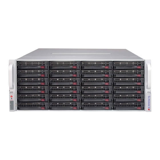
- Page 1 UPER ® SC847J CHASSIS SERIES SC847E16-RJBOD1 SC847E26-RJBOD1 USER’S MANUAL...
- Page 2 SC847J Chassis Manual The information in this User’s Manual has been carefully reviewed and is believed to be accurate. The vendor assumes no responsibility for any inaccuracies that may be contained in this document, makes no commitment to update or to keep current the information in this manual, or to notify any person or organization of the updates.
-
Page 3: Contacting Supermicro
Preface Contacting Supermicro Headquarters Address: Super Micro Computer, Inc. 980 Rock Ave. San Jose, CA 95131 U.S.A. Tel: +1 (408) 503-8000 Fax: +1 (408) 503-8008 Email: marketing@supermicro.com (General Information) support@supermicro.com (Technical Support) Web Site: www.supermicro.com Europe Address: Super Micro Computer B.V. Het Sterrenbeeld 28, 5215 ML 's-Hertogenbosch, The Netherlands Tel:... - Page 4 SC847J Chassis Manual Preface About This Manual This manual is written for professional system integrators and PC technicians. It provides information for the installation and use of the SC847J chassis. Installation and maintenance should be performed by experienced technicians only. This manual lists compatible parts available when this document was published.
- Page 5 Preface Manual Organization Chapter 1: Introduction The first chapter provides a checklist of the main components included with this chassis and describes the main features of the SC847J chassis. This chapter also includes contact information. Chapter 2: System Safety This chapter lists warnings, precautions, and system safety. It is recommended that you thoroughly familiarize yourself with installing and servicing the chassis and all safety precautions.
- Page 6 SC847J Chassis Manual This section lists compatible cables, power supply specifications, and compatible backplanes. Not all compatible backplanes are listed. Refer to our Web site for the latest compatible backplane information. Appendix A: Cables and Hardware This section provides information on cabling, and other hardware which is compat- ible with your chassis.
-
Page 7: Table Of Contents
Preface Table of Contents Contacting Supermicro ..................iii Chapter 1 Introduction Overview ......................1-1 Shipping List ....................1-1 Where to get Replacement Components ............1-2 Returning Merchandise for Service..............1-3 Chapter 2 System Safety Overview ......................2-1 Warnings and Precautions ................2-1 Preparing for Setup .................. - Page 8 SC847J Chassis Manual Ambient Operating Temperature ..............5-3 Reduced Airflow ....................5-3 Mechanical Loading ..................5-3 Circuit Overloading ..................5-3 Reliable Ground ....................5-3 Rack Mounting Instructions ................5-4 Identifying the Sections of the Rack Rails ............5-4 Locking Tabs ....................5-5 Releasing the Inner Rail .................
-
Page 9: Chapter 1 Introduction
Chapter 1: Introduction Chapter 1 Introduction Overview Optimized for enterprise-level heavy-capacity storage applications, Supermicro's SC847 JBOD chassis features up to 45x (24 front + 21 rear) 3.5" hot-swap HDD bays. The SC847 server chassis offers the option to reduce the number of HDDs to 36 (24 front + 12 rear) allowing for an optional motherboard to be installed. -
Page 10: Where To Get Replacement Components
SC847J Chassis Manual Where to get Replacement Components Though not frequently, you may need replacement parts for your system. To en- sure the highest level of professional service and technical support, we strongly recommend purchasing exclusively from our Supermicro Authorized Distributors/ System Integrators/Resellers. -
Page 11: Returning Merchandise For Service
Chapter 1: Introduction Returning Merchandise for Service A receipt or copy of your invoice marked with the date of purchase is required be- fore any warranty service will be rendered. You can obtain service by calling your vendor for a Returned Merchandise Authorization (RMA) number. When returning to the manufacturer, the RMA number should be prominently displayed on the outside of the shipping carton, and mailed prepaid or hand-carried. - Page 12 SC847J Chassis Manual Notes...
-
Page 13: Chapter 2 System Safety
Chapter 2: System Safety Chapter 2 System Safety Overview This chapter provides a quick setup checklist to get your chassis up and running. Following the steps in order given should enable you to have your chassis set up and operational within a minimal amount of time. This quick setup assumes that you are an experienced technician, familiar with common concepts and terminology. -
Page 14: Electrical Safety Precautions
SC847J Chassis Manual Electrical Safety Precautions Basic electrical safety precautions should be followed to protect yourself from harm and the SC847J from damage: • Be aware of the locations of the power on/off switch on the chassis as well as the room’s emergency power-off switch, disconnection switch or electrical outlet. -
Page 15: General Safety Precautions
Chapter 2: System Safety • Please handle used batteries carefully. Do not damage the battery in any way; a damaged battery may release hazardous materials into the environment. Do not discard a used battery in the garbage or a public landfill. Please comply with the regulations set up by your local hazardous waste management agency to dispose of your used battery properly. - Page 16 SC847J Chassis Manual • Touch a grounded metal object before removing any board from its antistatic bag. • Do not let components or PCBs come into contact with your clothing, which may retain a charge even if you are wearing a wrist strap. •...
-
Page 17: Chapter 3 System Interface
Chapter 3: System Interface Chapter 3 System Interface Overview There are several LEDs on the control panel as well as others on the drive carriers to keep you constantly informed of the overall status of the system as well as the activity and health of specific components. -
Page 18: Control Panel Buttons
SC847J Chassis Manual Control Panel Buttons There are two push-buttons located on the left handle of the chassis. These are (in order from top to bottom) a power on/off button and a reset button. Power: The main power button is used to apply or remove power from the power supply to the server system. - Page 19 Chapter 3: System Interface NIC1: Indicates network activity on GLAN1 when flashing. NIC2: Indicates network activity on GLAN2 when flashing. Overheat/Fan Fail: When this LED flashes, it indicates a fan failure. When con- tinuously on (not flashing) it indicates an overheat condition, which may be caused by cables obstructing the airflow in the system or the ambient room temperature being too warm.
-
Page 20: Drive Carrier Leds
SC847J Chassis Manual Drive Carrier LEDs Your chassis uses SAS/SATA. SAS/SATA Drives Each SAS/SATA drive carrier has two LEDs. • Blue: Solid on = Drive is present and available. Blinking = Drive is actively being accessed. Each Serial ATA drive carrier has a blue LED. When illuminated in a solid on state, this blue LED (on the front of the SAS/SATA drive carrier) indicates drive activity. -
Page 21: Chapter 4 Chassis Setup And Maintenance
Chapter 4: Chassis Setup and Maintenance Chapter 4 Chassis Setup and Maintenance Overview This chapter covers the steps required to install components and perform mainte- nance on the chassis. The only tool you will need to install components and perform maintenance is a Phillips screwdriver. -
Page 22: Removing The Chassis Cover
SC847J Chassis Manual Removing the Chassis Cover Figure 4-1: Removing the Chassis Cover Removing the Chassis Cover Unplug the chassis from any power source Remove the screws securing the cover to the chassis. Lift the cover up and off the chassis. Warning: Except for short periods of time, do NOT operate the server without the cover in place. -
Page 23: Installing Removable Hard Drives
Chapter 4: Chassis Setup and Maintenance Installing Removable Hard Drives Figure 4-2: Removing a Hard Drive Carrier Removing Hard Drive Carriers from the Chassis Press the release button on the drive carrier. This extends the drive carrier handle. Use the handle to pull the drive carrier out of the chassis. - Page 24 SC847J Chassis Manual Dummy Drive Drive Carrier Figure 4-3: Chassis Drive Carrier The drives are mounted in drive carriers to simplify their installation and removal from the chassis. These carriers also help to promote proper airflow for the drive bays. Warning: Except for short periods of time (while swapping hard drives), do not operate the server with the drives removed from the chassis drive bays.
- Page 25 Chapter 4: Chassis Setup and Maintenance SAS/SATA Hard Drive Drive Carrier Figure 4-5: Installing the Hard Drive into the Carrier Slide the hard drive into the carrier with the printed circuit board side facing down. Carefully align the mounting holes in both the drive carrier and the hard drive. Secure the hard drive to the carrier using six screws.
-
Page 26: System Fans
SC847J Chassis Manual System Fans Seven hot-swappable, heavy-duty fans provide cooling for the chassis. These fans circulate air through the chassis thereby lowering the chassis internal tempera- ture. Release Tab Air Direction Indicator Figure 4-7: System Fan Replacing a System Fan Open the chassis while the power is running to determine which fan has failed. - Page 27 Chapter 4: Chassis Setup and Maintenance Figure 4-8: Placing the System Fan...
-
Page 28: Power Supply
SC847J Chassis Manual Power Supply The SC847J chassis has a 1400 Watt high-efficiency redundant power supply. This power supply is auto-switching capable. This enables it to automatically sense and operate at a 100v to 240v input voltage. An amber light will be illuminated on the power supply when the power is off. - Page 29 Chapter 4: Chassis Setup and Maintenance Figure 4-10: Power Supply Release Tab 4. Replace the failed power module with the same model. 5. Push the new power supply module into the power bay until you hear a click. 6. If using only one power supply, plug the AC power cord back into the module and power up the server.
- Page 30 SC847J Chassis Manual Notes 4-10...
-
Page 31: Chapter 5 Rack Installation
Chapter 5: Rack Installation Chapter 5 Rack Installation Overview This chapter provides a quick setup checklist to get your chassis up and running. Following these steps in the order given should enable you to have the system operational within a minimal amount of time. Unpacking the System Inspect the box which the chassis was shipped in and note if it was damaged in any way. -
Page 32: Warnings And Precautions
SC847J Chassis Manual Warning! Warnings and Precautions Rack Precautions • Ensure that the leveling jacks on the bottom of the rack are fully extended to the floor with the full weight of the rack resting on them. • In single rack installations, stabilizers should be attached to the rack. •... -
Page 33: Rack Mounting Considerations
Chapter 5: Rack Installation • Always keep the rack's front door and all panels and components on the servers closed when not servicing to maintain proper cooling. Rack Mounting Considerations Ambient Operating Temperature If installed in a closed or multi-unit rack assembly, the ambient operating tempera- ture of the rack environment may be greater than the ambient temperature of the room. -
Page 34: Rack Mounting Instructions
SC847J Chassis Manual Rack Mounting Instructions This section provides information on installing the chassis into a rack unit with the rails provided. There are a variety of rack units on the market, which may mean that the assembly procedure will differ slightly from the instructions provided. You should also refer to the installation instructions that came with the rack unit you are using. -
Page 35: Locking Tabs
Chapter 5: Rack Installation Locking Tabs Each inner rail has a locking tab. This tab locks the chassis into place when installed and pushed fully into the rack. These tabs also lock the chassis in place when fully extended from the rack. This prevents the server from coming completely out of the rack when when the chassis is pulled out for servicing. -
Page 36: Installing The Inner Rails On The Chassis
SC847J Chassis Manual Inner Rails Figure 5-3: Installing the Inner Rails Figure 5-4: Inner Rails Installed on the Chassis Installing The Inner Rails on the Chassis Installing the Inner Rails Confirm that the left and right inner rails have been correctly identified. Place the inner rail firmly against the side of the chassis, aligning the hooks on the side of the chassis with the holes in the inner rail. -
Page 37: Installing The Outer Rails On The Rack
Chapter 5: Rack Installation L-min=676.00(26.61")(outer rail) 21D01 Figure 5-5: Extending and Releasing the Outer Rails Installing the Outer Rails on the Rack Installing the Outer Rails Press upward on the locking tab at the rear end of the middle rail. Push the middle rail back into the outer rail. -
Page 38: Standard Chassis Installation
SC847J Chassis Manual Ball-Bearing Shuttle Figure 5-6: Installing into a Rack Standard Chassis Installation Installing the Chassis into a Rack Confirm that the inner rails are properly installed on the chassis. Confirm that the outer rails are correctly installed on the rack. Pull the middle rail out from the front of the outer rail and make sure that the ball-bearing shuttle is at the front locking position of the middle rail. -
Page 39: Optional Quick Installation Method
Chapter 5: Rack Installation Optional Quick Installation Method The following quick installation method may be used to install the chassis onto a rack. Installing the Chassis into a Rack Install the whole rail assembly onto the rack as described on page 5-7. Release the inner rail without retracting the middle rail. -
Page 40: Adapters For Round And Threaded Hole Racks
SC847J Chassis Manual Adapters for Round and Threaded Hole Racks The SC847J chassis includes adapter brackets for those customers using round hole racks or racks with threaded holes size M5 or larger. Installing the Adapter Bracket Place the hooks of the front of the outer rail into the square holes of one of the adapter brackets. -
Page 41: Appendix A Sc847J Cables And Hardware
Appendix A: Chassis Cables Appendix A SC847J Cables and Hardware A-1 Overview This appendix lists supported cables for your chassis system. It only includes the most commonly used components and configurations. For more compatible cables, refer to the manufacturer of the motherboard you are using and our Web site at: www.supermicro.com. - Page 42 SC847J Chassis Manual A-3 Compatible Cables These cables are compatible with the SC847J Chassis. Alternate SAS/SATA Cables Some compatible motherboards have different connectors. If your motherboard has only one SAS connector that the SAS/SATA cables must share, use one of the following cables.
- Page 43 Appendix A: Chassis Cables Extending Power Cables Although Supermicro chassis are designed with to be efficient and cost-effective, some compatible motherboards have power connectors located in different areas. To use these motherboards you may have to extend the power cables to the mother boards.
- Page 44 SC847J Chassis Manual A-4 Chassis Screws The accessory box includes all the screws needed to set up your chassis. This section lists and describes the most common screws used. Your chassis may not require all the parts listed. HARD DRIVE Flat head Pan head 6-32 x 5 mm...
-
Page 45: Appendix B Sc847J Power Supply Specifications
Appendix B: Power Supply Specifications Appendix B SC847J Power Supply Specifications This appendix lists power supply specifications for your chassis system. SC847J 1400W MFR Part # PWS-1K41P-1R 1100W: 100 - 140V, 50 - 60Hz, 9.5 - 13.5 Amp AC Input 1400W: 180 - 240V, 50 - 60Hz, 7.0 - 9.5 Amp DC Output 4 Amp +5V Standby... - Page 46 SC847J Chassis Manual Notes...
-
Page 47: Appendix C Sas2-846El Backplane Specifications
Safety Information and Technical Specifications Appendix C SAS2-846EL Backplane Specifications To avoid personal injury and property damage, carefully follow all the safety steps listed below when accessing your system or handling the components. C-1 ESD Safety Guidelines Electrostatic Discharge (ESD) can damage electronic com ponents. To prevent dam- age to your system, it is important to handle it very carefully. - Page 48 SAS2-846EL Backplane User's Guide C-3 An Important Note to Users All images and layouts shown in this user's guide are based upon the latest PCB Revision available at the time of publishing. The card you have received may or may not look exactly the same as the graphics shown in this manual. C-4 Introduction to the SAS2-846EL Backplane The SAS2-846EL backplane has been designed to utilize the most up-to-date tech- nology available, providing your system with reliable, high-quality performance.
- Page 49 Safety Information and Technical Specifications C-5 Front Connectors and Jumpers BPN-SAS2-846EL2 R4635 R4631 FAN_MONITOR_DISABLE BUZZER_ENB1 REV 1.10 FANFAIL1 OVERHEATFAIL1 MH14 DESIGNED IN USA FANFAIL_LED_DISABLE ACTLED1 SEC_J1 SEC_J0 SEC_J2 PRI_J0 PRI_J2 PRI_J1 BUZZER1 MH12 L147 EC17 C367 C872 BAR CODE C2926 C867 C865 SEC_MODE2...
- Page 50 SAS2-846EL Backplane User's Guide C-6 Front Connector and Pin Definitions 1. Primary I C Connector C Connector Pin Definitions The I C connector is used to monitor the power Pin# Definition supply status and to control the fans. See the Data table on the right for pin definitions. Ground Clock No Connection...
- Page 51 Safety Information and Technical Specifications 6. Fan Connectors Fan Connectors The 3-pin connectors, designated FAN1, Pin# Definition through FAN3, provide power to the fans. Ground See the table on the right for pin defini- +12V tions. Tachometer 7. - 13. SAS Connectors The primary and secondary sets of SAS connectors provide expander features in- cluding cascading and failover.
- Page 52 SAS2-846EL Backplane User's Guide C-7 Front Jumper Locations and Settings FANFAIL_LED_DISABLE BUZZER_ENB1 ACTLED1 BPN-SAS2-846EL2 R4631 R4635 FAN_MONITOR_DISABLE BUZZER_ENB1 REV 1.10 FANFAIL1 OVERHEATFAIL1 MH14 DESIGNED IN USA FANFAIL_LED_DISABLE ACTLED1 SEC_J1 SEC_J2 SEC_J0 PRI_J0 PRI_J2 PRI_J1 BUZZER1 MH12 FAN_MONITOR_DISABLE L147 EC17 SEC_MODE2 C367 C872 BAR CODE...
- Page 53 Safety Information and Technical Specifications General Jumper Settings Jumper Jumper Settings Note Factory Setting PRI_MODE1 and 2 Pins 2-3 Do not change Factory Setting SEC_MODE1 and 2 Pins 2-3 Do not change Debug, SMC internal use only. EXPDBG1 and 2 No jumper required (EXPDBG2 not present on SAS2-846EL2)
- Page 54 SAS2-846EL Backplane User's Guide C-8 Rear Connectors and LED Indicators SAS #5 SAS #23 SAS #11 SAS #17 SAS #4 SAS #22 SAS #16 SAS #10 SAS #21 SAS #9 SAS #15 SAS #3 SAS #14 SAS #20 SAS #2 SAS #8 SAS #13 SAS #7...
- Page 55 Safety Information and Technical Specifications Rear LED Indicators Rear Connector Hard Drive Activity LED Failure LED SAS #0 ACT #0 FAIL #0 SAS #1 ACT #1 FAIL #1 SAS #2 ACT #2 FAIL #2 SAS #3 ACT #3 FAIL #3 SAS #4 ACT #4 FAIL #4...
- Page 56 SAS2-846EL Backplane User's Guide Notes C-10...
- Page 57 Safety Information and Technical Specifications Dual Port and Cascading Configurations Single Ports SAS2-846EL1 backplanes have a single-port expander that accesses all hard drives and supports cascading. Dual Ports SAS2-846EL2 backplanes have dual-port expanders that access all the hard drives. These dual-port expanders support cascading, failover, and multipath. From HBA From HBA or higher...
- Page 58 SAS2-846EL Backplane User's Guide C-10 Failover The SAS2-846EL2 backplane has two expanders which allow effective failover. SAS HBA Single Host Bus Adapter In a single host bus configuration, the BPN-SAS2-846EL2 R4635 R4631 BUZZER_ENB1 FAN_MONITOR_DISABLE REV 1.10 FANFAIL1 OVERHEATFAIL1 MH14 DESIGNED IN USA ACTLED1 SEC_J1 SEC_J0...
- Page 59 Safety Information and Technical Specifications C-11 Chassis Power Card and Support Cables Chassis Power Card In a cascaded configuration, the first chassis includes a motherboard and at least one host bus adapter. Other servers in this enclosed system, include a power card.
- Page 60 SAS2-846EL Backplane User's Guide Connecting an Internal Host Bus Adapter to the Backplane The following section lists the most common cables used to connect the host bus adapter to the backplane. BPN-SAS2-846EL2 R4635 R4631 BUZZER_ENB1 FAN_MONITOR_DISABLE REV 1.10 FANFAIL1 OVERHEATFAIL1 MH14 DESIGNED IN USA ACTLED1...
- Page 61 Safety Information and Technical Specifications Cable Name: iPass (Mini-SAS) to iPass (Mini-SAS) Part #: CBL-0108L-02 Length: 39 cm (15 inches) Part #: CBL-0109L-02 Length: 22 cm (9 inches) Part #: CBL-0110L-02 Length: 18 cm (7 inches) Description: This cable has an iPass (SFF-8087/Mini-SAS) connector (36 pins) at each end.
- Page 62 SAS2-846EL Backplane User's Guide Connecting an External Host Bus Adapter to the Backplane This backplane supports external Host Bus Adapters. In this configuration, the HBA and the backplane are in different physical chassis. This allows a JBOD configura- tion system to connect to the other system that has a HBA. Single External Host Bus Adapter BPN-SAS2-846EL2 R4635...
- Page 63 Safety Information and Technical Specifications Supported External HBA to Backplane Cable Use the following cable if your external HBA has an InfiniBand connector. Figure C-10: External Cable (CBL-0166L) Cable Name: SAS EL2/EL1 Cascading Cable (External), 68cm Part #: CBL-0166L (SFF-8088 1x to SFF-8088 x1) Ports: Single or Dual Placement: External cable Description: External cascading cable.
- Page 64 SAS2-846EL Backplane User's Guide Connecting Multiple Backplanes in a Single Channel Environment This section describes the cables used when cascading from a single HBA. These connections use CBL-0167L internal cables and CBL-0166L external cables. BPN-SAS2-846EL2 R4635 R4631 BUZZER_ENB1 FAN_MONITOR_DISABLE REV 1.10 FANFAIL1 OVERHEATFAIL1 MH14...
- Page 65 Safety Information and Technical Specifications Single HBA Configuration Cables Single Port Cable Assembly Figure C-12: Single Port Internal Cable (CBL-0167L) Cable Name: SAS EL2/EL1 Backplane Cable (Internal) with 2-port Cascading Cable, 68 cm Part #: CBL-0167L (SFF-8087 to SFF-8088 x1) Ports: Single Placement: Internal cable Description: Internal cable.
- Page 66 SAS2-846EL Backplane User's Guide Connecting Multiple Backplanes in a Dual Channel Environment This section describes the cables used when cascading from dual HBAs. These connections use CBL-0168L internal cables and CBL-0166L external cables. BPN-SAS2-846EL2 R4635 R4631 BUZZER_ENB1 FAN_MONITOR_DISABLE REV 1.10 OVERHEATFAIL1 FANFAIL1 MH14...
- Page 67 Safety Information and Technical Specifications Dual HBA Configuration Cables Dual Port Cable Assembly Figure C-15: Dual Port Internal Cable (CBL-0168L) Cable Name: SAS Dual-port Cable Assembly, 68/76cm Part #: CBL-0168L Placement: Internal cable Ports: Dual Description: Internal cascading cable. Connects the backplane to the Host Bus Adapter (HBA) or external port.
- Page 68 SAS2-846EL Backplane User's Guide C-12 Supported Cascading Configurations Cascading allows the system to access data at a faster rate by allowing several backplanes to share resources to reduce latency time. The first backplane in a cascaded system requires a motherboard and an HBA. Other servers require a power control card with no motherboard and no HBA.
- Page 69 Safety Information and Technical Specifications Dual SAS HBA and Cascaded Configuration BPN-SAS2-846EL2 FAN_MONITOR_DISABLE R4635 R4631 REV 1.10 BUZZER_ENB1 FANFAIL1 OVERHEATFAIL1 MH14 DESIGNED IN USA FANFAIL_LED_DISABLE ACTLED1 SEC_J2 SEC_J1 SEC_J0 PRI_J0 PRI_J2 PRI_J1 BUZZER1 MH12 L147 EC17 C367 C872 BAR CODE C2926 C867 C865 SEC_MODE2 MH10 C870 MH11 PRI_MODE2...
- Page 70 SAS2-846EL Backplane User's Guide Notes C-24...
-
Page 71: Appendix D Sas2-847El Backplane Specifications
Appendix D: SAS2-847EL Backplane Specifications Appendix D SAS2-847EL Backplane Specifications To avoid personal injury and property damage, carefully follow all the safety steps listed below when accessing your system or handling the components. D-1 ESD Safety Guidelines Electrostatic Discharge (ESD) can damage electronic com ponents. To prevent dam- age to your system, it is important to handle it very carefully. - Page 72 SC847J Chassis Manual D-3 An Important Note to Users All images and layouts shown in this user's guide are based upon the latest PCB revision available at the time of publishing. The card you have received may or may not look exactly the same as the graphics shown in this manual. D-4 Introduction to the SAS2-847EL Backplane The SAS2-847EL backplane has been designed to utilize the most up-to-date tech- nology available, providing your system with reliable, high-quality performance.
- Page 73 Appendix D: SAS2-847EL Backplane Specifications D-5 Connectors, Jumpers and LEDs EC22 EC17 DESIGNED IN USA ACT22 PRI_I2C1 EC12 ACT21 C130 C361 C362 C129 BUZZER_ENB1 MDIO1 EC14 C134 C133 SEC_MODE2 SEC_MODE1 ACTLED1 UART_S1 PRI_MODE2 PRI_MODE1 FANFAIL_LED_DISABLE FAN3 FAN4 MDIO2 EXPDBG2 FAN_MONITOR_DISABLE EC15 OVERHEATFAIL1 EC13...
- Page 74 SC847J Chassis Manual D-6 Front Connector and Pin Definitions 1. Primary I C Connector C Connector Pin Definitions The I C connector is used to monitor the power Pin# Definition supply status and to control the fans. See the Data table on the right for pin definitions. Ground Clock No Connection...
- Page 75 Appendix D: SAS2-847EL Backplane Specifications 6. Fan Connectors Fan Connectors The 4-pin connectors, designated FAN1, Pin# Definition through FAN4, provide power to the fans. Ground See the table on the right for pin defini- +12V tions. Tachometer Empty 7. - 10. SAS Ports The primary and secondary sets of SAS ports provide expander features including cascading and failover.
- Page 76 EC12 ACT21 C130 SC847J Chassis Manual C129 D-7 Front Jumper Locations and Pin Definitions BUZZER_ENB1 MDIO1 EC14 C134 C133 PRI_MODE1 SEC_MODE2 ACTLED1 SEC_MODE1 PRI_MODE2 PRI_MODE1 FANFAIL_LED_DISABLE FAN4 FAN3 MDIO2 FAN_MONITOR_DISABLE PRI_MODE2 OVERHEATFAIL1 EC15 EC13 PWR1 PRI_J1 +12V PWR5 EC22 +12V EC17 DESIGNED IN USA ACT22 PWR2 +12V...
- Page 77 Appendix D: SAS2-847EL Backplane Specifications General Jumper Settings Jumper Jumper Settings Note Factory Setting PRI_MODE1 and 2 Pins 2-3 Do not change Factory Setting SEC_MODE1 and 2 Pins 2-3 Do not change MDI01 and 02 No jumper required SMC internal use only UART_P1 No jumper required Primary UART connector...
- Page 78 SC847J Chassis Manual D-8 Front LED Indicators EC22 EC17 DESIGNED IN USA ACT22 PRI_I2C1 EC12 ACT21 C130 C361 C362 C129 BUZZER_ENB1 MDIO1 EC14 C134 12V_LED1 FANFAIL1 C133 OVERHEATFAIL1 SEC_MODE2 ACTLED1 SEC_MODE1 UART_S1 PRI_MODE2 PRI_MODE1 FANFAIL_LED_DISABLE FAN3 FAN4 5V_LED1 MDIO2 EXPDBG2 FAN_MONITOR_DISABLE OVERHEATFAIL1 EC15...
- Page 79 Appendix D: SAS2-847EL Backplane Specifications D-9 Rear Connectors and LED Indicators ACT20 PRI_FLASH1 SEC_FLASH1 SAS #20 SAS #8 SAS #14 33 9 SAS #7 SAS #13 SAS #19 ACT12 FAIL12 FAIL6 SAS #18 SAS #6 SAS #12 SAS #2 SAS #5 SAS #17 SAS #11 33 9...
- Page 80 SC847J Chassis Manual Rear LED Indicators Rear Connector Hard Drive Activity LED Failure LED SAS #0 ACT #0 FAIL #0 SAS #1 ACT #1 FAIL #1 SAS #2 ACT #2 FAIL #2 SAS #3 ACT #3 FAIL #3 SAS #4 ACT #4 FAIL #4 SAS #5...
- Page 81 Appendix D: SAS2-847EL Backplane Specifications D-10 Cascading Configurations Single Ports SAS2-847EL1 backplanes have a single-port expander that access all hard drives and supports cascading. From HBA or higher backplane EC22 EC17 DESIGNED IN USA ACT22 PRI_I2C1 EC12 ACT21 C130 C361 C362 C129 BUZZER_ENB1 MDIO1...
- Page 82 SC847J Chassis Manual D-11 Failover The SAS2-847EL2 backplane has two expanders which allow effective failover. SAS HBA Single Host Bus Adapter In a single host bus configuration, the EC22 EC17 DESIGNED IN USA ACT22 PRI_I2C1 EC12 ACT21 C130 C361 C362 backplane connects to one Host Bus C129 BUZZER_ENB1...
- Page 83 Appendix D: SAS2-847EL Backplane Specifications D-12 Chassis Power Card and Support Cables Chassis Power Card In a cascaded configuration, the first chassis includes a motherboard and at least one Host Bus Adapter (HBA). Other servers in this enclosed system, include a power card.
- Page 84 SC847J Chassis Manual Connecting an Internal Host Bus Adapter to the Backplane The following section lists the most common cables used to connect the HBA to the backplane. EC22 EC17 DESIGNED IN USA ACT22 PRI_I2C1 EC12 ACT21 C130 C361 C362 C129 BUZZER_ENB1 MDIO1...
- Page 85 Appendix D: SAS2-847EL Backplane Specifications Cable Name: iPass (mini SAS) to iPass (mini SAS) Part #: CBL-0108L-02 Length: 39 cm (15 inches) Part #: CBL-0109L-02 Length: 22 cm (9 inches) Part #: CBL-0110L-02 Length: 18 cm (7 inches) Description: This cable has an iPass (SFF-8087/mini-sas) connector (36 pins) at each end.
- Page 86 SC847J Chassis Manual Connecting an External Host Bus Adapter to the Backplane This backplane supports external Host Bus Adapters. In this configuration, the HBA and the backplane are in different physical chassis. This allows a JBOD configura- tion system to connect to the other system that has a HBA. Single External Host Bus Adapter EC22 EC17...
- Page 87 Appendix D: SAS2-847EL Backplane Specifications Supported External HBA to Backplane Cable Use the following cable if your external HBA has an InfiniBand connector. Figure D-10: External Cable (CBL-0166L) Cable Name: SAS EL2/EL1 Cascading Cable (External), 68cm Part #: CBL-0166L (SFF-8088 1x to SFF-8088 x1) Ports: Single or Dual Placement: External cable Description: External cascading cable.
- Page 88 SC847J Chassis Manual Connecting Multiple Backplanes in a Single Channel Environment This section describes the cables used when cascading from a single HBA. These connections use CBL-0167L internal cables and CBL-0166L external cables. EC22 EC17 DESIGNED IN USA ACT22 PRI_I2C1 EC12 ACT21 C130...
- Page 89 Appendix D: SAS2-847EL Backplane Specifications Single HBA Configuration Cables Single Port Cable Assembly Figure D-12: Single Port Internal Cable (CBL-0167L) Cable Name: SAS EL2/EL1 Backplane Cable (Internal) with 2-port Cascading Cable, 68cm Part #: CBL-0167L (SFF-8087 to SFF-8088 x1) Ports: Single Placement: Internal cable Description: Internal cable.
- Page 90 SC847J Chassis Manual Connecting Multiple Backplanes in a Dual Channel Environment This section describes the cables used when cascading from dual HBAs. These connections use CBL-0168L internal cables and CBL-0166L external cables. EC22 EC17 DESIGNED IN USA ACT22 PRI_I2C1 EC12 ACT21 C130 C361...
- Page 91 Appendix D: SAS2-847EL Backplane Specifications Dual HBA Configuration Cables Dual Port Cable Assembly Figure D-15: Dual Port Internal Cable (CBL-0168L) Cable Name: SAS Dual-port Cable Assembly, 68/76cm Part #: CBL-0168L Placement: Internal cable Ports: Dual Description: Internal cascading cable. Connects the backplane to the Host Bus Adapter (HBA) or external port.
- Page 92 SC847J Chassis Manual D-13 Supported Cascading Configurations Cascading allows the system to access data at a faster rate by allowing several backplanes to share resources to reduce latency time. The first backplane in a cascaded system requires a motherboard and HBA. Other servers require a power control card with no motherboard and no HBA.
- Page 93 Appendix D: SAS2-847EL Backplane Specifications Dual SAS HBA and Cascaded Configuration This configuration EC22 EC17 DESIGNED IN USA ACT22 PRI_I2C1 requires zoning. See EC12 ACT21 C130 C361 C362 C129 BUZZER_ENB1 MDIO1 section 3-2 of this EC14 C134 C133 manual for zoning SEC_MODE2 ACTLED1 SEC_MODE1 UART_S1 PRI_MODE2 PRI_MODE1 FAN3 FAN4...
- Page 94 SC847J Chassis Manual Notes D-24...
-
Page 95: Appendix E Sc847J Chassis Internals And Externals
Appendix E: SC847J Chassis Internals and Externals Appendix E SC847J Chassis Internals and Externals Overview This appendix describes backplane and cabling information specific to the SC847J chassis. Revisions to the Data in this Appendix Content Revision History Date Revision Changes 2/5/10 Initial revision 2/19/10... - Page 96 SC847J Chassis Manual SC847J E16 Series SAS2 JBOD Chassis Each SC847J E16 series SAS2 JBOD chassis contains two SAS2 expander back- planes, forty-five 3.5” drives (SAS or SATA) and a PTJBOD card. The PTJBOD card drives the chassis LEDs and fans. See the CSE-PTJBOD-CB2 section below for details.The content of this appendix will focus on how this chassis can be configured both internally and externally.
- Page 97 Appendix E: SC847J Chassis Internals and Externals SAS2-846EL1/EL2 SAS2-846EL1 is one of the two expander backplanes which may be used in the SC847J chassis. This backplane supports twenty-four 3.5” SAS/SATA drives and operates at a theoretical SAS2 performance of 6Gbs per phy. It supports enclosure Section 1.2 - BPN-SAS2-846EL1/2 elements such as fan RPM, temperature and power through the SES-II interface.
- Page 98 SC847J Chassis Manual J0 - Inbound J1 - Outbound from an Initiating to Downstream System Picture of BPN-SAS2-847EL1 Picture of BPN-SAS2-847EL1 Figure 3 Figure E-3: SAS2-847EL1 Figure 3 There is also dual version of the same expander which has 2 expa There is also dual version of the same expander which has 2 expander chips therefore you There is also dual version of the same expander which has two expander chips so have two paths to each drive behind the expander.
- Page 99 Appendix E: SC847J Chassis Internals and Externals It combines four SFF 8087 cables into one simple connector boa the side of the chassis to be connected to the outside world. Belo This special connector combines four SFF 8087 cables into one simple connector the connectors look: board which is installed on the side of the chassis to be connected to the external systems.
- Page 100 SC847J Chassis Manual Below please see block diagram of how the connections are made, internally: Below please see block diagram of how the connections are made, internally: SAS2-846EL1 SAS2-847EL1 BPN-SAS2-847-EL1 847EL1 BPN-SAS2-846EL1 BPN-SAS2- SC847E16 JBOD SC847J E16 Series SFF 8088 x 4 SC847E16 JBOD SFF 8088 by four Picture of 846 &...
- Page 101 Appendix E: SC847J Chassis Internals and Externals Figure E-8: External Cables for Connecting Head Units to JBODs External c The RAID card in the head unit can cascade to the JBOD chassis either through units and J its own expanders or through its own external SFF 8088 connector. Supermicro’s Figure 7 AOC-SAS2LP-H4iR has one external connector for this purpose.
- Page 102 SC847J Chassis Manual Using a RAID/HBA Card and Expander to Connect Downstream The block diagram below illustrates a head unit being cascaded to an SC847J E16 series JBOD chassis downstream. Each of the backplanes in the JBOD unit are connected to separate connectors. One to the RAID card and the other to the expander in the head unit.
- Page 103 Appendix E: SC847J Chassis Internals and Externals Notes...
- Page 104 SC847J Chassis Manual Disclaimer (cont.) The products sold by Supermicro are not intended for and will not be used in life sup- port systems, medical equipment, nuclear facilities or systems, aircraft, aircraft devices, aircraft/emergency communication devices or other critical systems whose failure to per- form be reasonably expected to result in significant injury or loss of life or catastrophic property damage.